Chery A15. Manual - part 24


  Index      Chery     Chery A15 - service repair manual


Search            


Content   ..  22  23  24  25   ..


Chery A15. Manual - part 24


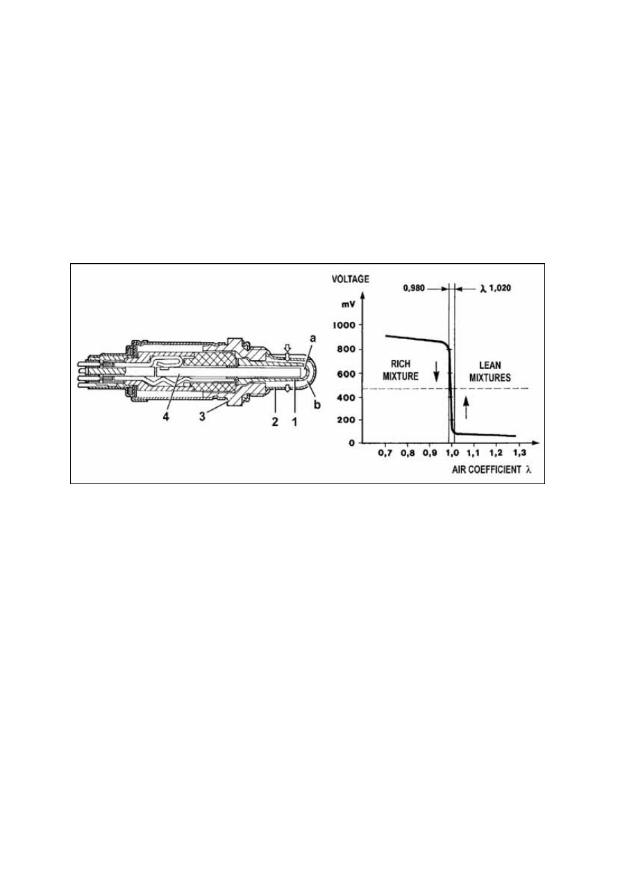
the mixture concentration value in time and change mixture thicker or thinner to make it 
always be close to chemical reaction equivalence ratio. The voltage range of which is 
0.980~1.020V. 

To reach working temperature rapidly (~300°C), a resistor (4) installed in the sensor can 
shorten the starting electric time of the porcelain. It means sensor can be installed in cold area 
of exhaust hose. If mixed gas concentration is thinner than chemical reaction equivalence ratio 
when working in full speed, ECU will give signal to the oxygen sensor to add mixture thicker 
(half-closed loop). 

Oxygen sensor doesn’t work under cut-off and full load condition, which is called open loop.


Recovery: 

If fault occurs in sensor or resistor, all information will be ignored and the whole system will 
work as an opened loop system.


Oxygen sensor test procedure: 

If diagnosis tester displays signal as “lambda sensor error “, please check: 

——

If there is air leakage in every manifold, pipes, brake booster, exhaust gas and fuel-vapor

re-cycle system. 

——

Spark wear and efficiency of high voltage wire insulator. 

——

If timing and positioning of TDC (top dead center)/rotate speed sensor is right or not. 

——

Tappet clearance and engine compression ratio. 

——

If supplied oil pressure is right or not. 


F-10

Exhaust gas emission            CO%           HC (p.p.m.)   CO2 (%) 

Before catalytic converter        0.4 - 1           < 600         > 12 

After catalytic converter         < 0.35            < 90         > 13 

See the above table, using three-way catalyst converter can reduce three types of harmful 
gases in exhaust gas at the same time: HC, CO, NO

x

, while harmless CO

2

 increases. 

The following factors will rapidly damage the catalytic converter: 

——

Fuel contained lead, which will decrease converter efficiency even invalidate catalytic 

converter. 

——

Incomplete burned fuel in converter, for example, the catalytic converter will be melt and 
damaged only in 30 seconds by the fuel under 800°C (temperature in converter). 

Do not cut off the high voltage cable no matter the engine is running for any reason to insure 
ignition parts (static ignition coil, high voltage cable, spark) are effective. 

Oxygen sensor signal is displayed on diagnosis tester. 

This value shall continuously wave in a defined range (thin mixture<0.45V, thick 
mixture>0.45V). 

Oxygen sensor heater resistance is about 4~5Ω at environment temperature 20°C, and its 

battery voltage is 12V.


ASSEMBLY AND DISASSEMBLY OF EXHAUST SYSTEM 

1. Installation of exhaust system with 

three-way catalyst converter: 


  ①  Installation of back hose hook: 

——

Install back hose hook on the dash 
panel of the body. 


——

Screw down M8 lock nut, screw 
down torque is 12±1Nm. 


  Installation of front hoses assembly: 


F-11

——

Install Oxygen sensor assembly on front hose assembly with a tightening torque of 
45±4.5Nm. 

——

Install 3 M10 double head studs on exhaust manifolds. 

——

Lay exhaust hose pad, install front hose assembly on exhaust manifolds. 

——

Mount 3 M10 copper nuts with a tightening torque of 60±3Nm.


  Installation of back hose assembly and three-way catalyst converter: 

——

Connect three-way catalyst converter assembly and back hose assembly flange with 2 
M8 bolts and 2 M8 flange plane nuts and lay sealing pad with a tightening torque of 
30±3Nm. The nuts shall near the three-way catalyst converter. 

——

Install back hose assembly on front hose assembly with a hose clamp. 

——

Connect back hose assembly to the back hose hook with a hang block. 


  Installation of three-way catalyst converter: 

——

Connect three-way catalyst converter assembly and front hose assembly flange with 2 
M8 bolts and 2 M8 flange plane nuts and lay sealing pad with a tightening torque of 
30±3Nm. 

——

Use one hang block connecting front hose of three-element catalytic converter to the 
hook of back hose. 


  Installation of back silencer: 

——

Install a buffer stopper on back silencer with a hose clamp around the opening position 
of back silencer. 

——

Set 2 hooks to welding bolts and tighten them using 2 M8 lock nuts with a torque of 
30±3Nm. 

——

Connect back silencer to the body with 4 flying rings (hang block). 


  Installation of front silencer: 

——

Install front silencer between three-way catalyst converter and back silencer. 

——

Install hose clamp assembly. 

——

Tighten all bolts in hose clamps and hose clamp assembly with a torque of 30±3Nm.        


F-12

Note:  

·Eccentricity between front silencer and the intake/exhaust hose is 18mm. Adjust front 

silencer position in assembly to guarantee a gap between the front silencer and the 
channel heat insulator more than 10mm. 

·In assembly, hose clamp should not be aslant installed around the exhaust hose. 

·Distance between the expanding section on exhaust hose and the section of hose 

clamp should be 14mm in assembly. 


  Installation of exhaust hose bracket: 

——

Install exhaust hose bracket. 

——

Mount 4 M8 lock nuts and tighten them with a torque of 12±1Nm. 


2. Examine gas leakage in exhaust system connection and its adjustment method: 

Examine leakage in exhaust system interface after engine warm-up. Certain amount of gas 
leakage is permitted (but not permitted in interface between exhaust manifolds and front hose 
assembly). It can be taken as a principle of no leakage if no engine wobble and no sound 
like ’pu’, ’pu’ in interface heard. If the above phenomenon is found, loosen the hose clamp in 
interface and rotate it a few circles, then tighten it again after adjusting installation direction 
of hose clamp. 

Installation of heat insulator 

——

Install each heat insulators to its proper position, and then tighten the clip.


F-13


Content   ..  22  23  24  25   ..