Chery A11. Manual - part 174
 

  Index      Chery     Chery A11 - service repair manual


Search            copyright infringement  


Content   ..  172  173  174  175   ..


Chery A11. Manual - part 174


    Maintenance Manual for Chery·Windcloud     

M7.9.7 EFI System


4. Knock Sensor KS 
 
Purpose:  
this sensor is designed to provide 
ECU with engine knocking information so 
as to carry out knocking control. 


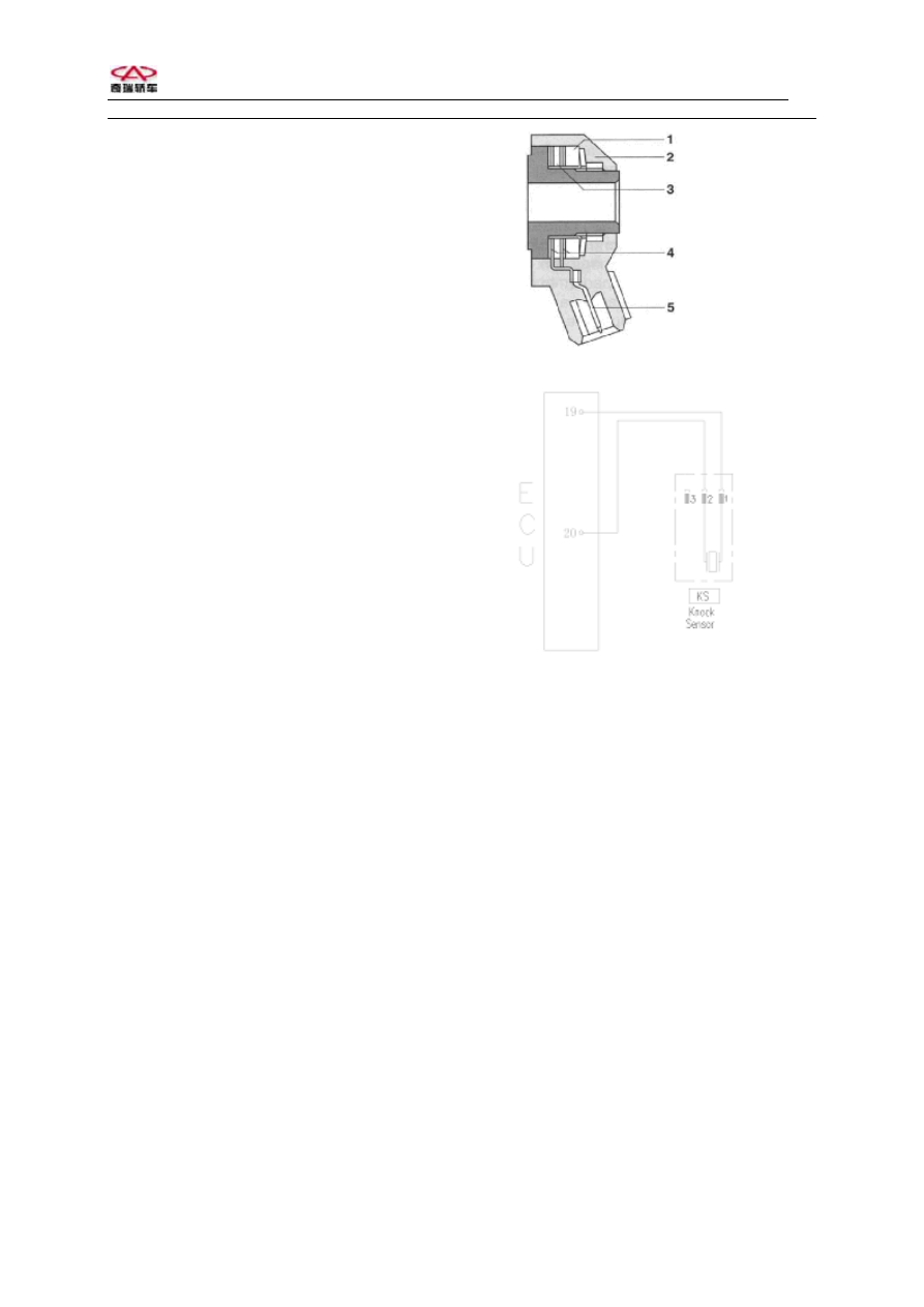
Composition and principle: knock sensor 
is a sort of vibration acceleration sensor, 
which is fixed on engine cylinder block. 
ECU controls engine ignition via signals 
detected by pressure-sensing element. 


Failure diagnosis: ECU monitors on 
various sensors, actuators, power 
amplification circuits and sensing circuits. In 
case any of the following situations occurs, 
failure mark of the knock sensor is set.   
Knock sensor failure 
Knocking control data processing circuit 
failure 
Cylinder-detecting signal is unreliable 
After failure mark of knock sensor being set, 
knocking closed-loop control is shut down, 
reduceing a safety angle from the ignition 
advance angle stored in ECU. When error 
frequency cuts down to below setting value, 
failure mark restores.


Installation hint: tightening torque is 
20±5Nm.


Knock sensor with cable 


1. Knocking block
2. Casing   

3. Piezoelectric ceramics
4. Contactor   
5. Electric connection


Circuit diagram of knock sensor 

 
Pins:  
1 Knock sensor signal 1 (ECU19#) 
2 Knock sensor signal 2 (ECU20#) 
 
Troubleshooting:  mainly check if there is 

short circuit or open circuit on the 

connection between 2 lines on senosr and 

corresponding ECU pins.   

If gasket is added during installation; if 

tightening torque is proper.   
If there is stitching defect between sensor 
and cylinder, or there is foreign matter 
between them. 


4

    Maintenance Manual for Chery·Windcloud     

M7.9.7 EFI System


5. Oxygen Sensor 
Purpose:  
this sensor is designed to provide 

the information that if there is surplus 

oxygen after full combustion of fuel, which 

is injected into engine cylinder in the intake 

air. ECU, when applying this information, 

can carry out fuel quantitative closed-loop 

control so as to achieve utmost conversion 

and purification of the three major toxic 

elements (HC, CO and NO

X

) in the engine 

exhaust with the application of three-way 

catalytic converter. 
Composition and principle: the sensing 

element of oxygen sensor is a porous 

ceramic pipe, the outer side of pipe wall is 

surrounded by engine exhaust, while inner 

side vents to atmosphere. According to 

inside and outside oxygen concentration 

difference, sensor figures out indirectly fuel 

injection pulse width, and then transfers the 

information to ECU, and the ECU controls 

the injection again. 

The working voltage of oxygen sensor 

fluctuates between 0.1-0.9V, 5-8 variations 

in 10 seconds is required; if lower than such 

frequency value, it shows that the sensor is 

aged, and needs replacement. The said 

sensor is unrepairable. 
Failure diagnosis: ECU monitors on 

various sensors, actuators, power 

amplification circuits and sensing circuits. In 

case any of the following situations occurs, 

failure mark of the oxygen sensor is set.   

Accumulator voltage is unreliable 

Manifold absolute pressure signal is 

unreliable 

Engine coolant temperature signal is 

unreliable.  

Injector driver stage failure 

After oxygen sensor failure mark is set, fuel 

quantification closed-loop control is shut 

down, and the primitive fuel injection time 

stored in ECU is used to carry out fuel 

quantification. 
Installation hints: the tightening torque of 

oxygen sensor is 50-60Nm, a layer of rust 

preventive oil shall be applied on oxygen 

sensor after replacing so as to prevent from 

incapable removal in case of rust. 
Troubleshooting: mainly check if the plug 

connection of several wires on the sensor is 

in good condition, and if there is short 

circuit or open circuit.   

Generally, sensor damage is caused by 

plumbum and phosphorus poisoning, so 

pay attention to fuel quality, meanwhile 

excessive consumption of engine oil is 

liable to result in sensor failure. 


Oxygen sensor 


Main relay

Oxygen 
sensor 

Circuit diagram of oxygen sensor 

Oxygen sensor has a cable, the other end of 

which is electric connection. The outside of 

sensor is wrapped with asbestos fireproof 

covering. 
There are 4 pins on the joint: 

1# connecting with heating control 

(ECU1#); 

2# connecting with heating power and main 

relay; 

3# connecting with sensor ground 

(ECU36#); 

4# connecting with signal (

+

) (ECU18#). 


Interior structure of oxygen sensor 


5

    Maintenance Manual for Chery·Windcloud     

M7.9.7 EFI System


6. Electronic Control Unit (ECU) 
 
Purpose:  
ECU is the core of electronic 
engine control system. Sensors sent various 
signals to ECU for electric control, and 
then ECU controls operations of fuel 
injector and ignition coil, etc. after internal 
calculation, thus controling working of 
engine. 


Normal operation voltage: 9-16V 


Composition:  it has shielded casing and 
printed circuit board, which integrates lots 
of electronic control units for the control of 
EFI system. 


Installation:  to be fixed by the support of 
bracket under pilot trench of front 
windshield. Pay attention to waterproofing.


ECU


Functions: 


Multipoint sequential injection 
Controlling ignition 
Idle speed control 
Independent knocking control on 
cylinder-by-cylinder basis (knock sensor 
KS-1); 
Providing sensors with power supply: 
5V/100mA 
Adopting cylinder-detecting signal (Phase 
sensor PG1) 
λ

closed-loop control with self-adaptation 

Controlling carbon canister control valve 
Air conditioning switch 
Engine-fault indicating lamp 
Fuel quantitative correction 
Engine speed signal output (TN signal) 
Speed signal input 
Failure self-diagnosis with flash code 
function 
Accepting engine load signal 


Troubleshooting: due to the fact that ECU 
(electric control unit) has low failure rate, so 
generally it is not advisable to replace ECU 
for troubleshooting on any problem. Failure 
of components such as periphery circuit and 
sensors shall be checked and solved firstly. 
Do not replace ECU until all periphery 
components are confirmed to be fault-free.


6

    Maintenance Manual for Chery·Windcloud     

M7.9.7 EFI System


3. ECU Pin Definition: 

Pin 

      Connected to 

Type 

Pin 

      Connected to 

Type 

Oxygen sensor heating 

Output

42 

Air  conditioning  temperature 
sensor 

Input 

Ignition coil 2 

Output

43 


3 Ignition 

ground 

Ground 44 Non-continuous power 

Input 

4  


45 Non-continuous 

power  Input 

Ignition coil 1 

Output

46 

Carbon canister valve 

Output 

Injection nozzle 4 (Cylinder 2) 

Output

47 

Injection  nozzle  3  (Cylinder 
4) 

Output 

Injection nozzle 2 (Cylinder 3) 

Output

48 


Engine speed signal output 

Output

49 


50 

Low speed fan control 

Output 

10 


51 

Electronic ground 2 

Ground 

11  


52   


12 

Continuous power 

Input 

53 

Electronic ground 1 

Ground 

13 Ignition 

switch 

Input 54   


14 Main 

relay 

Output

55   


15 

Engine rotational speed sensor A 

Input 

56 


16 

Throttle position sensor 

Input 

57 

Air  conditioning  compressor 
switch 

Input 

17 

Sensor ground 1 

Ground 58 


18 

Oxygen sensor 

Input 

59 

Speed signal 

Input 

19 Knock 

sensor 

Input 60   


20 

Knock sensor B 

Input 

61 

Power ground 1 

Ground 

22  


63  Non-continuous 

power 

Input 

23 


64 

Stepper motor Phase D 

Output 

24 


65 

Stepper motor Phase A 

Output 

25 


66 

Stepper motor Phase B 

Output 

26 


67 

Stepper motor Phase C 

Output 

27 

Injection nozzle 1 (Cylinder 1) 

Output

68 

High speed fan control 

Output 

28 


69 

Fuel pump relay 

Output 

29 

Inspection lamp 

Output

70 

Air conditioning compressor 
relay 

Output 

30 


71 

K wire diagnosis 

Input 
/output 

31  


72   


32 

5V power 2 

Output

73 


33 

5V power 1 

Output

74 


34 

Engine rotational speed sensor B 

Input 

75 

Air conditioning switch 

Input 

35 

Sensor ground 3 

Ground 76 

Blower switch 

Input 

36 

Sensor ground 2 

Ground 77 

Headlight switch 

Input 

37 

Intake pressure sensor   

Input 

78 


38  


79  Phase 

sensor 

Input 

39 

Engine coolant temperature sensor Input 

80 

Power ground 2 

Ground 

40 

Intake air temperature sensor 

Input 

81 


41  


7


Content   ..  172  173  174  175   ..