Chery A11. Manual - part 153
 

  Index      Chery     Chery A11 - service repair manual


Search            copyright infringement  


Content   ..  151  152  153  154   ..


Chery A11. Manual - part 153


  Maintenance Manual for Chery·Windcloud

Sunroof


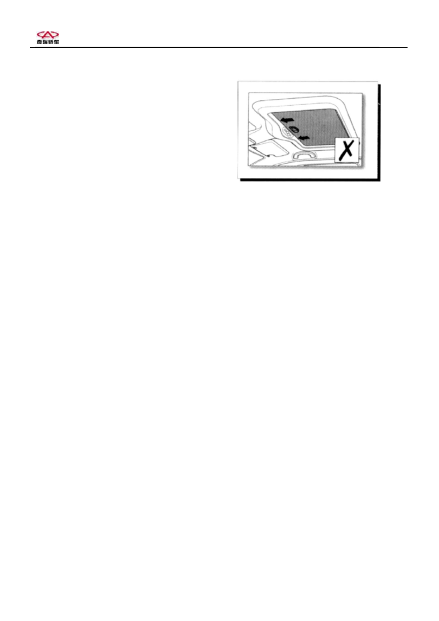
5.2.5 Never fully shut sunshade with sunroof being open 

during high-speed running. 


5.2.6 In case electric control of sunroof dose not work, or 

automatic shutting and sensoring failure, first 

check sunroof fuse. If the fuse is normal, please 

try reprogramming (refer to Maintenance Guide). 


Page 37 of 37 


Maintenance Manual for Chery·Windcloud                   

Marelli EFI System 


Chapter One: Operating Principle for 
Marelli EFI Control and Execute 
Components 
 
1. Intake Pressure and Intake Air 
Temperature Sensor 
Purpose: to 
detect absolute pressure of 

intake manifold from 10-115KPa and intake 

air temperature, to provide engine load 

information, and to identify the height above 

sea level and to conduct intake pressure 

compensation according to the intake 

pressure at certain engine speed and idle 

speed. 

 
Composition and principle: this sensor has 

two functions (i.e. manifold absolute 

pressure sensor and intake temperature 

sensor integrated in one unit), and is 

installed above pressure-stable cavity to 

detect absolute pressure of intake manifold 

(pressure-stable cavity), which is used to 

control fuel injection and ignition. 


Pressure-sensitive element inside intake 
pressure sensor
 detects signal of intake 

manifold pressure for injection pulse width 

control of EFI system. This sensor also 

serves as the substitute of a sensor of engine 

load signal. 
Intake air temperature sensing element is 

an NTC (Negative Temperature Coefficient) 

resistor, which is similar to that of water 

temperature sensor. While the intake air 

temperature increases, the resistance value 

decreases. And engine ECU monitors the 

variation of intake air temperature via a 

comparison circuit inside. 
Failure diagnosis: The monitor circuit 

inside ECU detects sensor circuit troubles 

such as open circuit, short circuit and sensor 

damages, etc. In case ECU detects any 

sensor output signal that goes beyond output 

characteristic curve, the sensor is diagnosed 

as failed by ECU.   
For example: when intake pressure is 

higher than upper limit or lower than lower 

limit, ECU detects sensor failure (in case 

that intake pressure is lower than lower limit 

when starting, ECU is able to recognize the 

starting condition), and the engine fault 

indicating lamp goes on. Under this 

condition the engine works in failure mode. 

When intake temperature sensor signal 

exceeds either upper or lower limit, engine 

ECU will light fault indicating lamp to 

remide driver that engine assumes failure 

mode. 

Installation: to be installed on pressurizer. 
Troubleshooting: mainly check if there is 

short circuit or open circuit on the 

connection between 4 lines on senosr and 

ECU.  

If there is short circuit, open circuit or 

grounding between sensor wire harnesses. 

Check system for air leakage, and check if 

all connections are in good condition. 


Manifold absolute pressure /intake air temperature sensor 


Intake temperature /
pressure sensor


Circuit diagram of manifold absolute pressure and intake 

air temperature sensor


Pins: 1# is grounded (connecting ECU 54#); 

2# outputs temperature signal 

(connecting ECU 55#);   

3# connects with standard 5V power 

source (connecting ECU 68#); 

4# outputs pressure signal (connecting 

ECU 75#). 


1


Maintenance Manual for Chery·Windcloud                   

Marelli EFI System 


2. Throttle Position Sensor 
 
Purpose:
 this sensor is designed to provide 
ECU with information of throttle angle. As 
per such information, ECU obtains 
information of engine load and operating 
condition (for instance: start-up, idle speed, 
reverse, partial load and full load) as well as 
of acceleration and deceleration. This sensor 
has three wires, and the throttle opening can 
be detected by ECU via monitoring voltage 
variation. 
Composition and principle: Consisting of 
two compass sliding contact resistors and 
two sliding contact arms, throttle position 
sensor is an angle sensor that outputs linear 
signals. The axes of contact arms are on the 
same axial line with throttle axis, with 5V 
power supply voltage U

S

 being applied to 

both ends of each contact resistor. When 
throttle turns, contact arms turn along with it 
and move on sliding contact resisters, 
educing potential of contacts U

P

 as output 

voltage. This sensor is actually an angle 
potentiometer. ECU adopts Up/Us votage 
ratio to avoid change in output signal due to 
fluctuation in engine voltage. 
 
Failure diagnosis: ECU monitors throttle 
angle, and detects sensor failure when 
output signal exceeds upper or lower limit. 
In addition, ECU detects sensor circuit 
errors such as short circuit and open circuit. 
In case any of these errors is detected, 
engine will work in failure mode, and fault 
indicating lamp will go on. 
Signal output: this sensor outputs 
0.5V

-4.9V DC voltage signals. Rotate the 

sensor to test the output signal, which shall 
be a continous signal without fluctuation or 
interruption. 
 
Installation:  allowable tightening torque 
for fastening screw is 1.5Nm-2.5Nm. 
 

Troubleshooting:  mainly check if there is 

short circuit or open circuit on the 

connection between 3 lines on senosr and 

ECU.  

Check to see if there is short circuit, open 

circuit or grounding between sensor wire 

harnesses.  


Throttle position sensor 


Throttle position sensor 

 
Circuit diagram of throttle position sensor 
 

Pins:  
 

1 throttle position sensor (ECU 76#) 

2 sensor signal ground (ECU 54#) 

3 sensor signal (ECU 60#) 
 
Warning:  under most circumstances, the 
removal of throttle position sensor is not 
allowed. 


2


Maintenance Manual for Chery·Windcloud                   

Marelli EFI System 


3. Coolant Temperature Sensor TF-W


Purpose: this sensor is designed to provide 
coolant temperature information. To provide 
engine ECU with water temperature signal 
used for control of ignition timing and fuel 
injection pulse width in startup, idle speed 
and normal operation. The main function of 
water temperature sensor is to provide 
engine with fuel injection pulse width signal 
during cold starting. The sensor also sends 
signals to control fan operation. 
Composition and principle:
 this sensor is a 
thermistor of negative temperature 
coefficient (NTC) with resistance value 
decreasing with the increasing of coolant 
temperature except linear relation. The said 
thermistor is installed in a heat-conducting 
sleeve. ECU monitors water temperature 
variation by converting resistance value of 
thermistor into a changing votage through a 
bleeder circuit (inner structure of ECU). 
Failure diagnosis: When coolant 
temperature is higher than allowed upper 
limit or lower than lower limit, failure mark 
of the knock sensor is set, engine fault 
indicating lamp goes on and engine works in 
failure mode. In this case ECU controls 
ignition and fuel injection according to set 
water temperature for failure mode, at the 
same time the fan is running at high-speed 
mode (normal fan control for system with 
fan controlled by a thermal switch). 
Limiting data: 2.5±5%KΩ 
Installation hint: tightening torque is 15Nm 
in maximum.   
Hints: the vehicle is equipped with 2 water 
temperature sensors, one is single-pin water 
temperature sensor, providing the water 
temperature gauge with water temperature 
signal; the other is double-pin, providing the 
engine ECU with water temperature signal. 
Caution: the two water temperature sensors 
have different resistance values. 


Coolant temperature sensor 


Water temperature sensor 

 
Circuit diagram of coolant temperature sensor


Pins:  this sensor has 3 pins, which can 

interchange for use.   

1 coolant temperature sensor signal (ECU 

54#) 
2 sensor signal ground (ECU 62#) 
Troubleshooting: mainly check if there is 

short circuit or open circuit on the 

connection between 2 lines on senosr and 

ECU connector.   

If there is short circuit, open circuit or 

grounding between sensor wire harnesses.   
Line grounding or defect grounding is liable 
to cause engine water temperature gauge to 
indicate excessive temperature. 
Check to see if ECU connector is loose. 
Make sure the connector is in good 
condition, for internal looseness may occur 
to ECU connector. 


3


Content   ..  151  152  153  154   ..