Chery A series. Manual - part 117
 

  Index      Chery     Chery A series - service repair manual


Search            copyright infringement  


Content   ..  115  116  117  118   ..


Chery A series. Manual - part 117


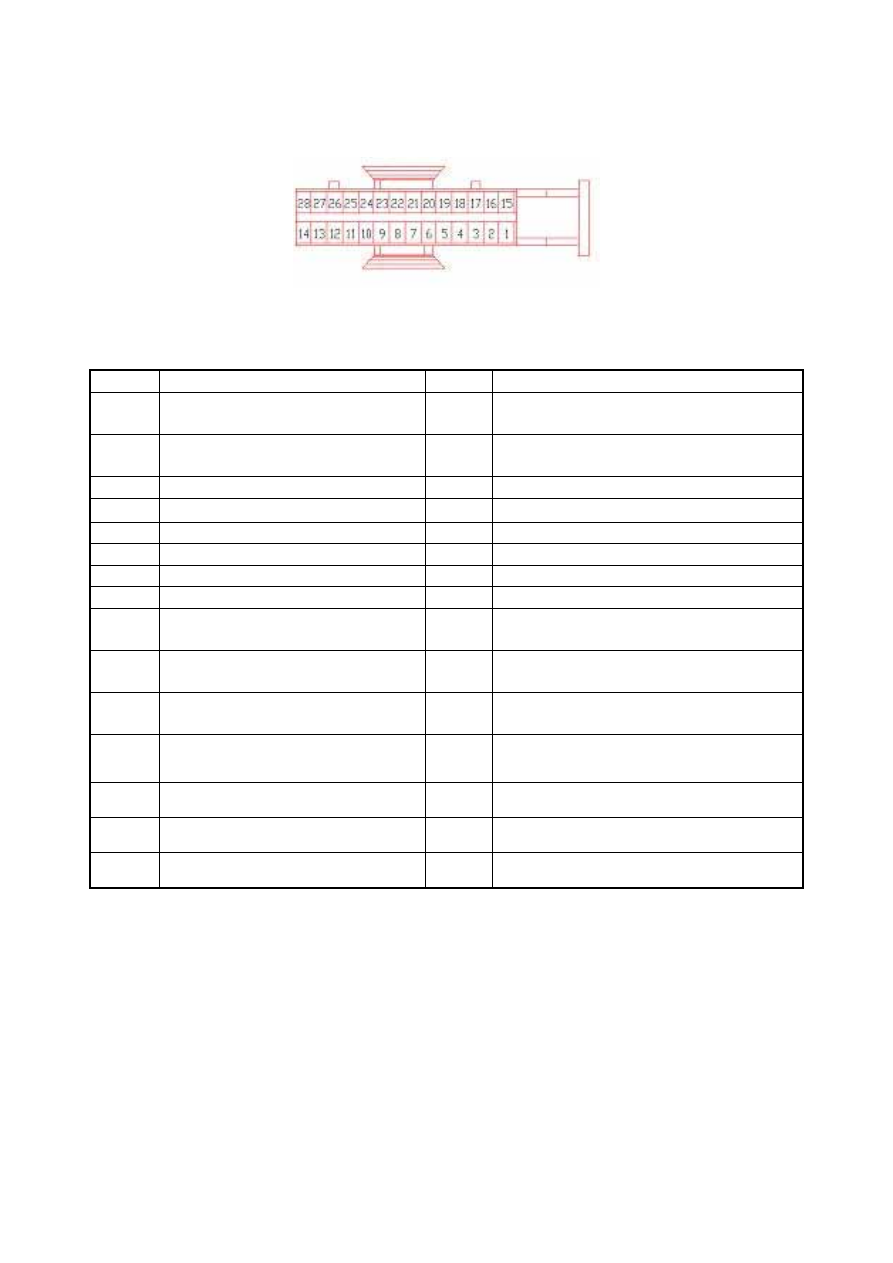
The 28-socket connector of the wiring harness of combination instrument 


The function of each socket is described in the table below: 

Socket Function Socket

Function 

1 No 

connected 16 

Connecting to the terminal D+ of 

generator 

Connecting to the water warning 

switch of water tank 

17 

Air bag warning signal 

Terminal 31# (ground) 

18 

Door light 

TX1 speed signal of Hall Sensor 

19 

Seat belt warning lamp 

Terminal 31# 

20 

Engine malfunction warning lamp 


21 

Connecting to the fuel meter sensor 


22 

Left-turn signal lamp 


23 

Water temperature signal of the ECU 

Oil pressure warning switch 

(30kpa) 

24 

Right-turn signal lamp 

10 The 

ECU 

A20RPM 25 

Power supply terminal for high beam 

indicator lamp 

11 

Terminal 30#, power supply for 

clock and multi-function display 

26 

Warning switch for brake oil level; 

indicator lamp switch for hand brake 

12 

Terminal 58b#, power supply for 

instrument panel illumination 

27 Speedometer 

sensor 

13 

Terminal 15# 

28 

Night illumination 

14 

ABS warning lamp 


15 Diagnostic 

wire   


T-26


1. SPEED ODOMETER 

The Chery sedan A15LHD employs the cross coil type speedometer to indicate the driving 
speed and accumulated road mileage, as well as equipped with digital odometer. The section 
for measuring car speed employs a magnetic type of structure, while the section for recording 
mileage is controlled by multifunction liquid crystal display. 

See figure (Illustration-2) 


                    Speedometer (Illustration-2) 

The indicator needle is located at the scale zero when the speedometer is not in use. When the 
car is driving, the transmission gear in the gearbox is activating and cutting the magnetic flux 
of the permanent-magnet of the Hall Speed Sensor, so that the latter will produce pulse 
signals to the cross coil type Speed Odometer to drive the indicator needle of speedometer, 
and meanwhile it will also provide the same signal to the mileage-recording multifunction 
liquid crystal display to control the mileage counting.   

2. WATER TEMPERATURE METER 

Water temperature meter 

The Chery sedan A15LHD employs the water temperature meter equipped with cross coil 
type indicator needle. See figure (Illustration-3)—the water temperature meter is located at 
left.  


Water temperature meter (Illustration-3) 


T-27


The pointer head of the cross coil meter is a kind of electromagnetic device. The coils are 
round on the surface of its magnetic rotor in four directions, with an included angle of 90º 
between the two adjacent coils. The strength of the current passing through the coils is 
depended on the resistance of the sensor, so that the magnetic flux densities produced by the 
coils in four directions are varied correspondingly, which subsequently activates the rotation 
of the magnetic rotor and the movement of indicator needle. 

3. FUNCTION AND PREINCIPLE OF WATER TEMPERATURE SENSOR 

The water temperature sensor of Chery sedan A15 LHD employs the thermo-sensitive 
resistance, which is shown in the figure above: 

The coolant temperature sensor is used to inspect working temperature of the engine; the 
ECM will provide the best control program for the engine according to different temperature 
environment; 

Composition and working principle: The sensor is a thermo-sensitive resistance of negative 
temperature coefficient (NTC). Its resistance will decrease as the coolant temperature 
increases, but not linearly related. This thermo-sensitive resistance of negative temperature 
coefficient is loaded into a copper heat-conducted sleeve. The ECU converts the changes of 
value of the thermo-sensitive resistance into variable voltages supplying the ECU via a 
divider circuit so as to monitor the changes of the water temperature. (ECU’s internal 
structure) 

Pin: the sensor has 3 interchangeable pins totally. 

1 Coolant temperature sensor signal (ECU39#) 

2 Sensor signal ground (ECU35#) 

3 Another wire is used to connect the water temperature signal of the instrument.   

Installation: the coolant temperature sensor is mounted on the sub-loop passage of the coolant 
behind the engine. 


Notes on installation:

 M

aximum tightening torque is 15Nm. 

4. PRODUCT CHARACTERISTICS   

Working voltage: 5V DC 

Working temperature: -40 ~ 135

o

Figure of coolant temperature sensor 

T-28


The thermo-sensitive resistance is made of a kind of semiconducting material with negative 
temperature coefficient, where its resistance will sharply decrease as the temperature 
increases. 


5. FUEL METER   

The operation of the fuel meter is basically the same as the water temperature meter. It is also 
the cross coil type of indicator needle meter. See figure below (Illustration-5)—the fuel meter 
is located at right of the figure. 


Fuel meter (Illustration-5) 

When the float is moving along with the fuel level in the fuel tank, the sliding contact linked 
with the float staff will respond accordingly so as to change the value of the thick-film 
resistance. When the fuel tank is full, the value of the thick-film resistance will be the 
minimum and the current of the cross coil will be the maximum. The indicator needle of the 
fuel meter points at the maximum scale F. On the contrary, when the fuel in the tank is 
exhausted, the value of thick-film resistance will be the maximum, and the indicator needle 
deflexion value of the fuel meter points being the minimum scale E. 

The relationship between fuel quantity and resistance is indicated in the table below. 

The relationship between fuel quantity and resistance 

Float position 

Capacity (L) 

Resistance (Ω) 

Empty  

283 

Half full 

30 

89 

Full 55  36 


FAULT DIAGNOSIS AND TROUBLESHOOTING 


T-29


Content   ..  115  116  117  118   ..