Chery A series. Manual - part 81
 

  Index      Chery     Chery A series - service repair manual


Search            copyright infringement  


Content   ..  79  80  81  82   ..


Chery A series. Manual - part 81


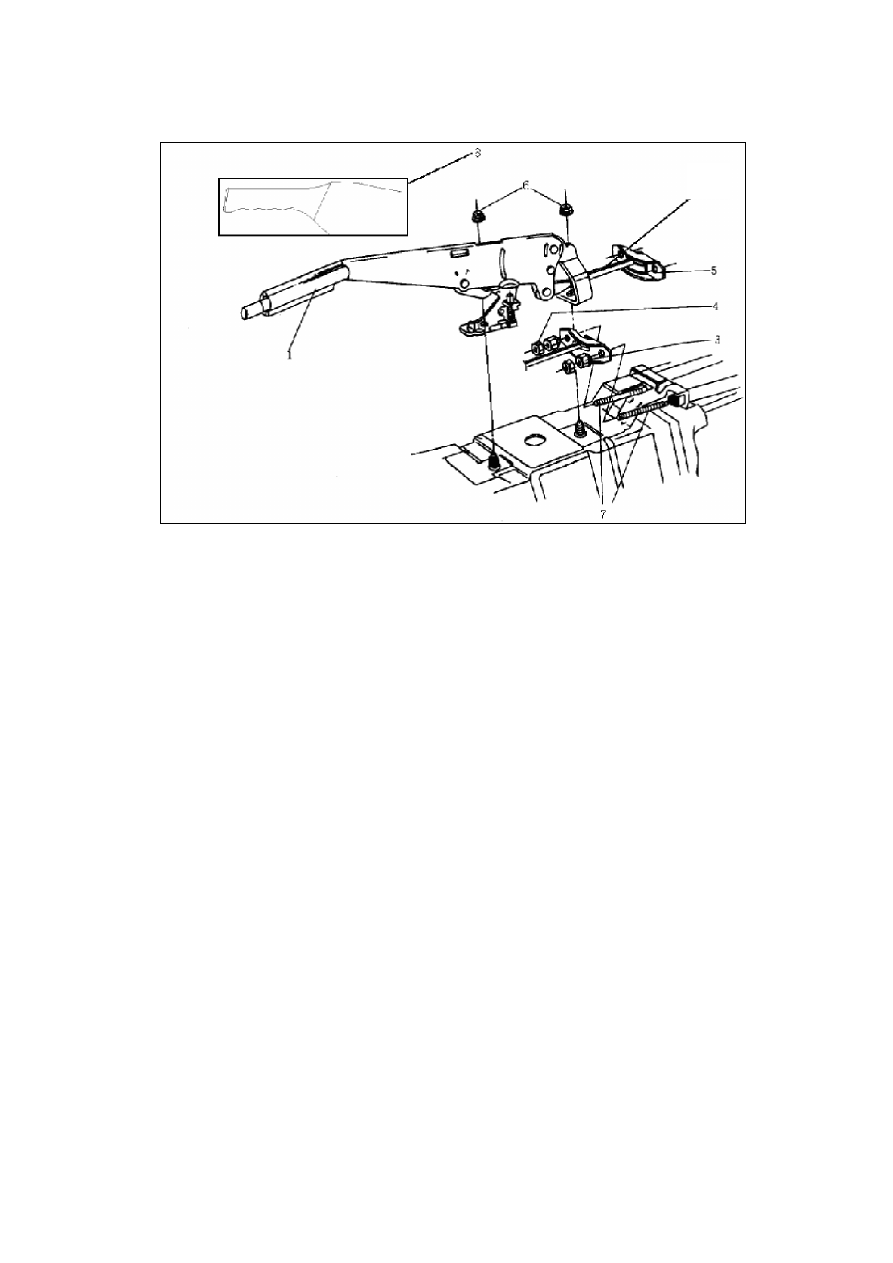
Disassembly/Assembly and Installation of Parking Brake System

(as shown in the figure above)

Fit the parking brake dust cover assy. tightly on the parking brake control mechanism, and
use the nuts to secure the parking brake control mechanism assy. onto the welding pegs on
the vehicle body.
*   Remove the tire and rear wheel brake drum, and detach the brake cable clip and parking

brake cable suspension clamp, which the tightening clips on the rear axle are available for
the bottom of body

*  Remove the auxiliary instrument panel (see the Disassembly/Assembly of Auxiliary

Instrument Panel)

*   Remove the parking brake cable and compensation rod connection adjusting nut and lock

nut; And the tightening torque of lock nut is 9±3 Nm.

*   Install the hand brake cable and control rod in the reverse order of removal.

1. Brake control rod

5. Compensation rod

2. Tie rod

6. Nut (20Nm)

3. Adjusting nut

7. Parking brake cable

4. Lock nut (8Nm)

8. Parking brake dust cover assy.

Adjustment of Parking Brake

(as shown in the figure below)

2

P-18

The rear brake is an automatic adjusting intermittent
drum brake, so it is necessary to adjust the parking
brake under the normal use, and it is required to
adjust the brake only when replacing the parking
brake cable, brake shoe assy. or brake wheel
cylinder. Adjust it in accordance with the following
procedures:

-- Loosen the handle of parking brake.

-- Forcefully step on the brake pedal once.

-- Pull the handle of parking brake upwards 4

ratchets.

-- Tighten the adjusting nut until the two wheels isn't

available to be turned by hand, as shown in the
figure.

-- Unclip the parking brake, and check whether the

two rear wheels operate freely.

ABS (ANTI-LOCK BRAKE SYSTEM) CONTROL SYSTEM

INTRODUCTION TO ABS CONTROL SYSTEM

Chery’s A15LHD series vehicle adopts the MK
series ABS system manufactured based on the
imported technology. The system is the current
newest generation of anti-lock brake system all
over the world, which has the EBD (Electronic
Brake Distribution) function, and it is unnecessary
to prepare for the brake proportion control valve.
This system has the following characteristics:

*    Integrated module structure design

*   Small dimension, light weight and low cost

*   Security and reliable, easy to maintenance

*   With the failure information storage and

self-diagnostics interfaces

DISASSEMBLY/ASSEMBLY AND INSTALLATION OF ABS CONTROLLER

Adjusting Nut

Adjusting Nut

P-19

Notices:

*    Use the diagnostic tester to find out the
seasons of failures, and then repair it;

*    Unpack the spare part packaging just
before the beginning of installation;

*    Only the original parts are available;

*    Pay more attention to the cleanliness during
repair, and wipe it only with the non-woolen
cloth;

*    Use the cleaning agent without the mineral
oil to wipe the outside surface clean before
repair;

*    Do not use the compressed air or move the
vehicle when the system activates;

*    Remove the ABS assy., and use the proper
plugs to block all outlets of hydraulic equipment
quickly as possible;

*    Remove other parts which may disturb the
repair operation;

*    Please use the brake fluid DOT 4, and do
not apply any mineral oil;

*    Use the brake fluid to soak the seals and
O-ring, and it is prohibited to use the engine oil
or ointment;

*    Check the availability of the regular brake
system and ABS brake function after the
completion of repair;

Check the leakage of all joints of hydraulic

pipes.

Removal of MK20-I HECU assy.

*   Turn off the ignition switch and disconnect the
negative wire of battery;

*   Remove the electrical harness from the ABS
assy.;

*   Step the pedal downwards >60 mm, and use the
pedal support to fasten it; It will shut down the

P-20

central valve of main bump and thus the brake fluid
can’t flow out from the outlet when the system
activates;

*   Remove the brake pipe A and B (connected to
the main pump) from the HCU, and then mark
them and use the plugs to block the outlet
immediately;

*   Remove the brake hose 1 to 4 connected to all
wheels, and then mark them and use the plugs to
block the outlets immediately;

*   Remove the nut cap used to secure the HECU
on the support;

*   Remove the whole HECU from its support.

Replacement of Hydraulic Control Unit/ Electronic
Control Unit

*   Press down the locking located at the joint side, and

remove the electric harness from the pump motor;

*   Remove the 4 screws shown in the figure, the

removed old screws of which are not available;

*   Detach the Hydraulic Control Unit (HCU) from the

Electronic Control Unit (ECU);

*   Install a new Hydraulic Control Unit (HCU) on the

Electronic Control Unit (ECU);

*   Use the new screws to tighten the ECU on the HCU

with the tightening torque of 3+1Nm;

*   Connect the harness of motor, and take care that the

locking must be in place.

Caution: The air bleeding operation must be

conducted after replacing the hydraulic
control unit.

P-21


Content   ..  79  80  81  82   ..