Chery A series. Manual - part 32
 

  Index      Chery     Chery A series - service repair manual


Search            copyright infringement  


Content   ..  30  31  32  33   ..


Chery A series. Manual - part 32


supply, short to ground or open, the malfunction flag 
bit is set. The closed loop control of the oxygen sensor 
and its memory precontrol are disabled, but the last 
data stored in its memory is valid. After the 
malfunction is fixed, the malfunction flag bit will be 
reset. 

Working pressure: 350 kPa 

Resistance of the fuel injector: 11-16

Ω 

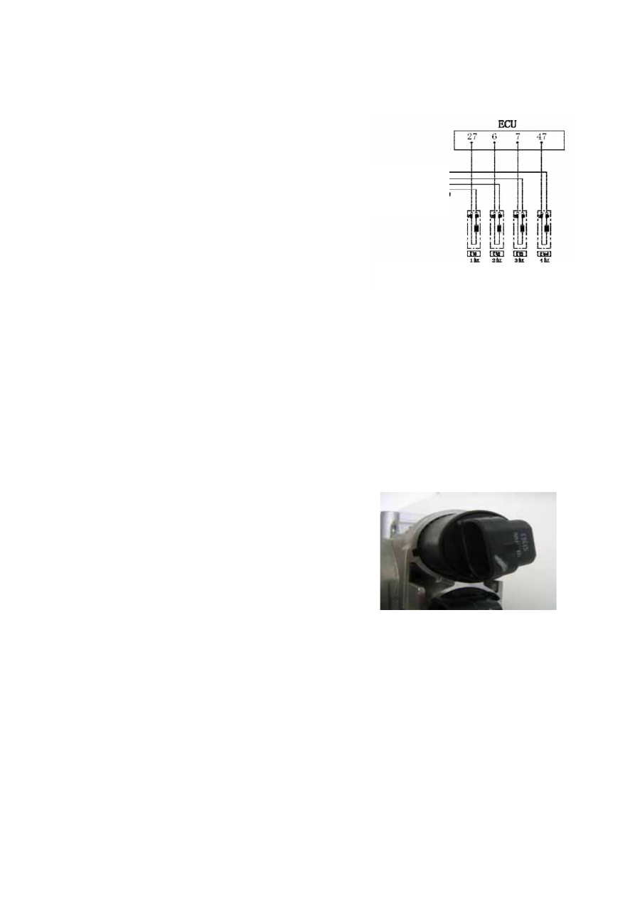
Pins  Each fuel injector has two pins. Of which the 
one marked by “+” is connected to the 87# pin of 
output terminal of the fuel pump relay; the other is 
connected to the 27#, 6#, 7#, or 47# pin of the ECU 
respectively. 


Troubleshooting:  The common malfunctions of the 
fuel injector such as unsmooth fuel injection and 
defective atomization are normally resulted due to long 
term use of the engine. So the fuel injector shall be 
cleaned periodically. The circuit short or open in the 
internal coil of the fuel injector also will result 
malfunction of the fuel injection system. Verify that the 
system circuits are short or open. 


  Idle actuator with step motor DLA 

Function:  The idle actuator with step motor is also 
equipped with a bypass air intake duct. If the throttle is 
closed air can enter the engine through such bypass 
duct. The ECU can adjust the sectional area of the 
bypass duct through this step motor, control the air 
intake flow and in turn control the quantity of fuel 
injection based on the air flow. The increase or 
decrease of the engine rotary speed can be achieved 
through increasing or decreasing the sectional area of 
the bypass duct under idle speed, through which the 
closed loop control of engine rotary speed under idle 
speed is achieved eventually. 


Connected to the 
87# pin of the 
 main relay 

Circuit diagram of the solenoid fuel injector
 

Idle actuator with step motor


G-17


Structure and working principle: The step motor is a 
micro-motor, which is comprised of steel stators 
installed in a circle and a rotor. Each steel stator has a 
coil. The rotor is permanent magnet and the center of 
the magnet is a nut. All the coils of stators are always 
on. If the current direction of any coil is changed, the 
rotor will turn by an angle. If all coils of stators change 
their currents directions in a proper order, a rotating 
magnetic field will be generated and result in the 
permanent magnet rotor rotating in designed direction. 

Fault diagnosis: The ECU can detect the circuit short 
and circuit open in the two coils of the idle step motor. 
Upon the occurrence of such malfunction the engine 
malfunction alarm light will be lit and the engine will 
enter the malfunction operation mode. 


Pins: 

Pin A is connected to the 29# pin of ECU; 
Pin B is connected to the 4# pin of ECU; 
Pin C is connected to the 26# pin of ECU; 
Pin D is connected to the 21# pin of ECU. 

Troubleshooting: Verify that the four circuits between 
the step motor and the ECU are short or open. Verify 
that the step motor is jammed. Verify that there is 
circuit short or circuit open inside the step motor. 


  Ignition coil ZSK-ROV 

Function: The ignition coil transforms the low voltage 
of the primary winding into the high voltage of the 
secondary winding. The spark plug generates the spark 
through discharging and ignites the combustion gas 
mixed with air and fuel. 

Structure and working principle: The ignition coil is 
comprised of the primary winding, the secondary 
winding, the iron core, the shell and so on. If the 
battery voltage applies on the primary winding, the 
primary winding is charged. After the ECU cut off the 
circuit of the primary winding the charging will be 
stopped and the high voltage will be inducted in the 
secondary winding. 


Fault diagnosis: Because the ECU is not able to 
conduct diagnosing for the ignition coil, there is no 
diagnostic trouble code for the malfunction of the 
ignition coil. Whether the ignition coil functions 
properly can be judged only by inspecting the ignition 

il

i t

Th i iti

il

d

it

l t


Circuit of the stepper of the idle

The step motor   
of the idle actuator

External appearance of 


G-18


coil resistance. The ignition coil produces quite a lot 
heat under normal operation and the over temperature 
of ignition coil will result in such malfunctions as 
increase of the ignition coil’s resistance, unstable 
operation of the engine and engine stall. 

Primary winding: 0.47 ohms 

Secondary winding: 8 ohms 

Pins: 

1# pin of the primary winding is connected to the 5# 
pin of ECU; 
2# pin of the primary winding is connected to the 2# 
pin of ECU; 
3# and 4# pins are jointly connected to the positive grid 
of power supply. 

High voltage side: 1#, 2#, 3# and 4# pins are 
connected respectively to the spark plug of the cylinder 
with the same number through the distributor circuit. 

Troubleshooting:  Verify that there is circuit short or 
circuit open in the coils.   
Verify that there is electrical leakage and crack on the 
shell.  
Verify that the electricity for ignition is not sufficient 
due to coil ageing. 


Carbon canister control valve 

Function: It is used to control the purge airflow of the 
carbon canister. The carbon canister control valve is 
controlled by the ECU through the pulse length and 
frequency (i.e. duty ratio) based on the engine load. 
The excessive accumulation of fuel vapor in the carbon 
canister will result in fuel spill and environment 
pollution, so the function of the solenoid valve of the 
carbon canister is to open the valve at an appropriate 
time so that the excessive fuel vapor can enter the air 
intake pipe and participate in the combustion. 


Structure and working principle: The carbon canister 
is comprised of magnetic coil, armature, valve and 
other elements. There is a filter screen at its inlet. The 
airflow passing the carbon canister control valve is not 
only relative to the duty ratio of the pulse which is sent 
by the ECU to the carbon canister control valve, but 
also relative to the pressure difference between the exit 
and inlet of the carbon canister control valve. If there is 
no pulse, the carbon canister control valve is closed. 


Ignition coil with double spark 

87# main relay 

Circuit diagram of the ignition coil 


G-19


The ECU can indirectly control the purge airflow 
through controlling the charging time of the carbon 
canister solenoid valve based on the signals provided 
by various sensors of the engine. 

Fault diagnosis: The ECU doesn’t have the function of 
self-diagnosis for the carbon canister control valve, but 
has the function of self-diagnosis for the driving stage 
of control valve of carbon canister. If the driving state 
of the control valve of carbon canister is short or 
overloaded to the battery voltage, short to ground or 
open, the basic memory of the closed loop control of 
fuel quantity will be closed, the memory of idling air 
demand quantity will be closed and the memory data at 
that time is valid. The common malfunctions of engine 
are unstable idling or excessive high idle speed under 
the malfunction of the solenoid valve of carbon 
canister. 

Pins: 

1# pin is connected to the 87# pin on output terminal of 
the main relay; 
2# pin is connected to the 46# pin of ECU. 

Troubleshooting:  The blockage and crack of the 
carbon canister will result in the increase of air intake. 


  Steel fuel distribution pipe assembly 

Function: Store and distribute the fuel and provide a 
relative stable pressure for the fuel injection system so 
as to achieve the uniform fuel supply pressure and 
quantity for each cylinder and stable operation of 
engine. 

Structure:  The fuel distribution pipe assembly is 
comprised of fuel distribution pipe (KVS-S) and fuel 
injector (EV). 

Installation requirement: The connection of fuel pipe 
and rubber hose shall be fastened by clamp. The model 
of the selected clamp shall match to the rubber hose to 
ensure the seal connection between the fuel pipe and 
the rubber hose. 

Fault diagnosis: There is seldom possibility for the 
malfunction occurrence in the main fuel supply pipe. 
Most of the malfunctions, which result in the leakage of 
the fuel system, are caused by poor assembly, so proper 
note shall be paid during installation that any used 
O-oil seal shall not be used again and appropriate 
lubricant is allowed to be painted during assembly. 


Carbon canister control valve 

Carbon canister control valve

Circuit diagram of the solenoid valve
of the charcoal canister TEV-2


G-20


Content   ..  30  31  32  33   ..