Loader Bobcat 853, 853H. Manual - part 63
VALVE CLEARANCE
Adjustment
Make the valve clearance adjustment with engine
stopped and cold.
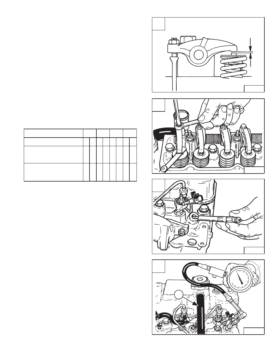
The correct clearance is 0.016 inch (0,41 mm) with the
engine cold [A].
Put the correct size feeler gauge between the rocker arm
and the valve stem. Turn the adjustment bolt until the
clearance is correct [B].
Use the following sequence to set the valve clearance:
Cylinder No.
1
2
3
4
Valve arrangement
I
E
I
E
I
E
I
E
Piston in No. 1 cylinder is
at TDC on compression
stroke
Piston in No. 4 cylinder is
at TDC on compression
stroke
• • •
•
• •
• •
Front
Rear
ENGINE COMPRESSION
Checking
The tools listed will be needed to do the following
procedure:
OEM1074 – Engine Compression Kit
MEL1268 – Compression Gauge Test Adapter
The engine must be at operating temperature.
Remove the glow plugs [C]. (See Page 7–40.)
Install the correct compression adapter into the cylinder
head.
Connect the compression gauge [D].
The engine must be turning at about 175 RPM.
The compression must be between 300–500 PSI
(2069–3448 kPa) with no more than 50 PSI (345 kPa)
difference between cylinders.
The engine has an open crankcase ventilation system.
The ventilation hose comes from the valve cover tube
(Item 1) [D] and passes down the side of the engine block.
A
B–04123
0.016 inch
(0,41 mm)
Cold
C
B–08922
D
B–08920
1
853, 853H Loader
–7–41–
Service Manual
B
B–08934