Loader Bobcat 773. Manual - part 115
 

  Index      Bobcat     Bobcat 773 - service manual 1997 year


Search            


Content   ..  113  114  115  116   ..


Loader Bobcat 773. Manual - part 115


CONTROL HANDLE (ADVANCED HAND CONTROL)
(AHC) (Cont’d)

Switch Handle Removal And Installation (Cont’d)

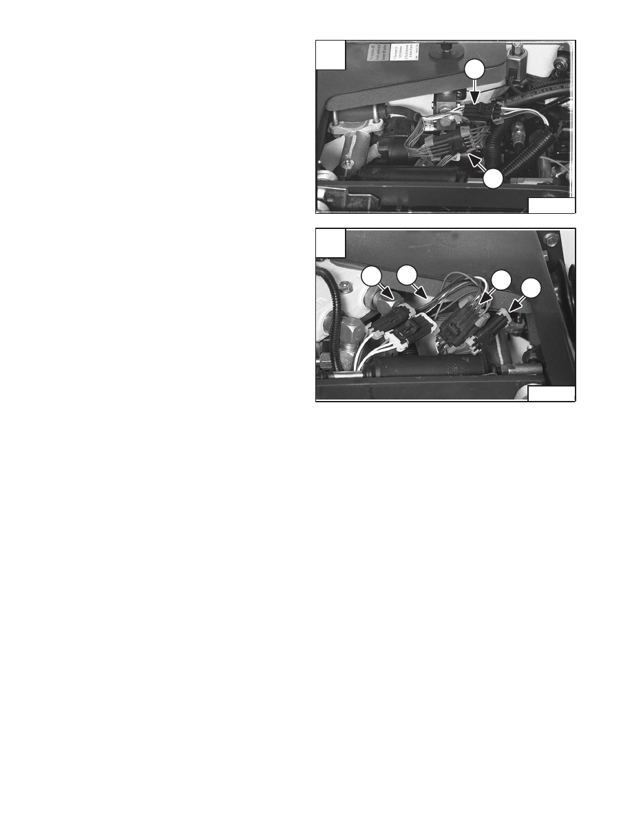
Disconnect the right switch handle connectors (Items 1 &
2) [A] from the loader wiring harness connectors.

Disconnect the left switch handle connectors (Items 1, 2,
3 & 4) [B] from loader wiring harness connectors.

Remove the connector locks and connectors from the
wires to remove the switch handle from the steering
handle.

Installation:The wire colors of the steering lever harness
are as follows:

Right Switch Handle

  Eight–Pin Connecter

A–Terminal – Dark. Orange/White
B–Terminal – Green
C–Terminal – Dark Blue
D–Terminal – Dark Blue/White
E–Terminal – Dark Blue/Yellow
F–Terminal – Pink/Red
G–Terminal – Pink/Black
H–Terminal – Pink/Gray

  Six–Pin Connector

A–Terminal – Orange
B–Terminal – Light Green/White
C–Terminal – Light Green
D–Terminal – Yellow
E–Terminal – Blank
F–Terminal – Blank

Left Switch Handle

  Eight–Pin Connector

A–Terminal – Yellow
B–Terminal – Green
C–Terminal – Brown
D–Terminal – Orange
E–Terminal – Orange/Blue
F–Terminal – Brown/Red
G–Terminal – Brown/Black
H–Terminal – Brown/Green

  Three–Pin Connector

A–Terminal – Orange/White
B–Terminal – Yellow/Red
C–Terminal – Yellow/Green

  Two–Pin Connector

A–Terminal – Purple
B–Terminal – Purple/Blue

  Two–Pin Connector (Water Kit)

A–Terminal – White
B–Terminal – Blue

A

N–17779

1

2

–10–24–

Service Manual

773 BICS Loader

Revised June 01

B

N–17772

1

3

2

4

C

N–17471

1

CONTROL HANDLE (ADVANCED HAND CONTROL
(AHC) (Cont’d)

Switch Handle Removal And Installation (Cont’d)

Roll the pistol grip handle cover (Item 1) [A] down.

Using a small screwdriver, lift the handle tabs (Item 2) [A]
and slightly rotate the switch handle.

Pull the switch handle and wiring harness assembly (Item
1) [B] from the steering lever.

Installation:  When installing the switch handle and
wiring harness assembly into the steering handle, route
the harness (Item 1) [C] to assure proper return of the
control handle to neutral position and minimize harness
movement.

A

N–17382

1

2

2

B

N–17383

1

–10–25–

Service Manual

773 BICS Loader

Revised June 01

CONTROL HANDLE (ADVANCED HAND CONTROL)
(AHC) (Cont’d)

AHC Handle Removal And Installation

Remove the handle control unit. (See Page 10–19.)

Remove the switch handle. (See Page 10–23.)

Remove the rubber handle cover (Item 1) [A] from the
handle.

Using a small screwdriver, hold the handle spacer (Item
1) [B] and remove the allen head screws (Item 2) [B] from
the handle assembly.

Installation: Tighten the allen head screws to 35 in.–lbs.
(4 Nm) torque.

A

N–17384

1

–10–26–

Service Manual

773 BICS Loader

Revised Nov. 01

B

N–17385

1

2

2

CONTROL HANDLE (ADVANCED HAND CONTROL)
(AHC) (Cont’d)

AHC Handle Disassembly And Assembly

Remove the handle sleeve (Item 1) [A] and bushings
(Item 2) [A] from the handle.

Check all parts for wear and replace as needed.

Check the mounting bolt (Item 1) [B] that connects the
handle to the handle control unit for wear, replace as
needed.

A

N–17394

1

2

2

Service Manual

–10–27–

773 BICS Loader

Revised June 01

B

N–17393

1


Content   ..  113  114  115  116   ..