Loader Bobcat 773. Manual - part 112
HANDLE CONTROL UNIT TEST (Cont’d)
Procedure (Cont’d)
Left Handle Test With Test Harness;
Raise the operator cab. (See Page 1–1.)
Connect the remote start switch. (See Page 1–1.)
The test harness (MEL1555) and a digital multimeter are
necessary to complete the following procedure.
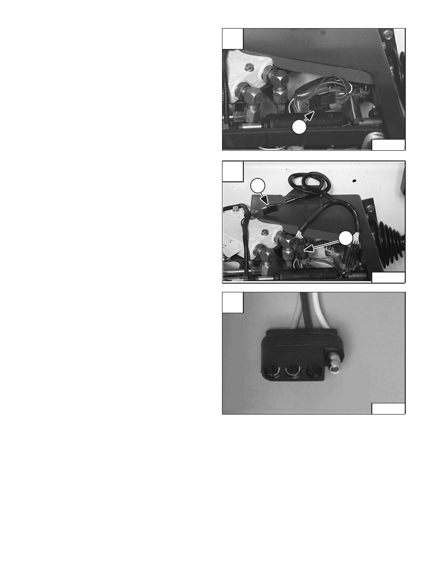
Disconnect the handle control harness (Item 1) [A].
Install the test harness (Item 1) [B].
Move handle to the neutral position.
Turn the key to the ON position with the engine OFF.
With a digital multimeter take a voltage reading at the four
prong terminal connector (Item 2) [B].
The sensor supply voltage between ground, terminal 1
and terminal 3 [C] should be 4.3
±
0.1
volts (5.0
±
0.1
volts Hall–Effect).
The signal voltage reading between the ground, terminal
1 and terminal 2 [C] should be 1.7 to 2.1 volts (1.97 to 2.44
volts*).
NOTE: Terminal 4 [C] is an open terminal not used at
this time.
Left Handle Test Without Test Harness;
A digital multimeter is necessary to complete this test.
For the switch handle harness connector color code. (See
Page 10–24.)
The test must be run at the eight pin switch handle
connector (Item 1) [A]. The wiring harness connectors
must remain connected to complete this test.
Check the sensor supply voltage (4.3
±
0.1
volts) (5.0
±
0.1
volts*) between terminal G (Brown/Black) and
terminal F (Brown/Red).
Check the signal voltage between terminal G
(Brown/Black) and terminal H (Brown/Green). The
voltage should be between 1.7 to 2.1 volts (1.97 to 2.44
volts*).
Diagnosis Results for both Tests;
If the sensor supply voltage is 4.3
±
0.1
volts (5.0
±
0.1
volts*), continue on and check the signal voltage.
If the sensor supply voltage is less than 4.3
±
0.1
volts
(5.0
±
0.1
volts*) or 0 volts, check the PWM fuse, check
for shorts or opens in the wiring harness. If there are no
apparent shorts or opens change the AHC/PWM
controller. (See Page 10–15.)
If the sensor supply voltage is more than 4.3
±
0.1
volts
(5.0
±
0.1
volts*) check for a short to a power wire in the
wiring harness. If there are no apparent shorts, change
the AHC/PWM controller. (See Page 10–15.)
If the signal voltage is in the range of 1.7 to 2.1 volts (1.97
to 2.44 volts*) the system is functioning properly. The
nominal voltage reading is 1.89 volts (2.2 volts*). If the
signal voltage is not in the range of 1.7 to 2.1 volts (1.97
to 2.44 volts*) change the handle controller.
* Hall–Effect (Identified by yellow push button float
switch on left–hand handle.
B
P–17771
1
2
1
A
N–17770
–10–12–
Service Manual
773 BICS Loader
Revised Nov. 01
C
P–13754
1
3
2
4