Audi TT (2007 year). Manual - part 191


  Главная      Audi     Audi TT (2007 year) (4-cylinder TDI engine (2.0 ltr. 4-valve common rail), mechanics Engine ID CBB) - Workshop Manual


поиск по сайту            


содержание   ..  189  190  191  192   ..


Audi TT (2007 year). Manual - part 191


Protected by copyright. Copying for private or commercial purposes, in part or in whole, is not 
 permitted unless authorised by AUDI AG. AUDI AG does not guarantee or accept any liability 
     with respect to the correctness of information in this document. Copyright by AUDI AG.

15

16

17

18

19

20

21

22

23

24

25

26

27

28

8J0-060030410

*

SA

1

SA

2

SA

3

SA

4

SA

5

SA

6

SA

7

SA

8

B272

J

293

C

G

B698

J

533

C

1

16.0

rt

E1

6.0

rt/gn

D1

35.0

sw

14

C1

25.0

sw

A1

B+

0.35

vi/ws

A1

LIN

T4a

/1

0.35

vi/ws

T4a

/1

0.35

vi/ws

T20d

/12

0.35

vi/ws

3

B1

F1

G1

H1

J1

A2

14

3

ws = white

sw = black

ro

= red

br

= brown

gn

= green

bl

= blue

gr

= grey

li

= purple

ge

= yellow

or

= orange

rs

= pink

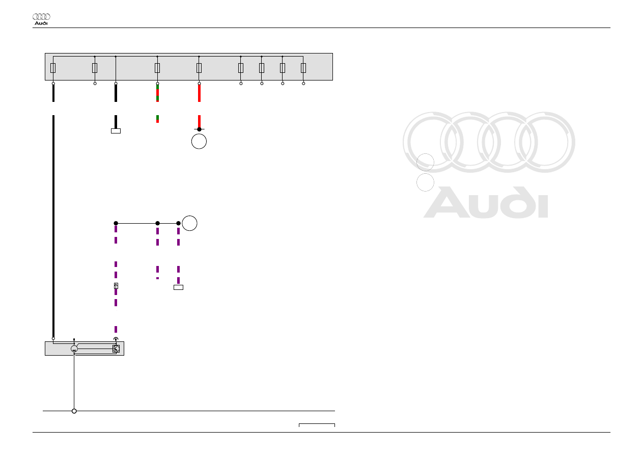
Alternator

C

Alternator

C1

Voltage regulator

J293 Radiator fan control unit

J533 Data bus diagnostic interface

SA1 Fuse 1 in fuse holder A

SA2 Fuse 2 in fuse holder A

SA3 Fuse 3 in fuse holder A

SA4 Fuse 4 in fuse holder A

SA5 Fuse 5 in fuse holder A

SA6 Fuse 6 in fuse holder A

SA7 Fuse 7 in fuse holder A

SA8 Fuse 8 in fuse holder A

T4a 4-pin connector, front left in engine compartment

T20d 20-pin connector

B272 Positive connection (30), in main wiring harness

B698 Connection 3 (LIN bus) in main wiring harness

*

Main fuse carrier, in E-box on left of plenum chamber

 Audi TT

Current Flow Diagram

No.  60 / 3

 04.2010

Protected by copyright. Copying for private or commercial purposes, in part or in whole, is not 
 permitted unless authorised by AUDI AG. AUDI AG does not guarantee or accept any liability 
     with respect to the correctness of information in this document. Copyright by AUDI AG.

2.0l petrol engine , CESA, CETA

From June 2010

 Audi TT

Current Flow Diagram

No.  61 / 1

 04.2010

Protected by copyright. Copying for private or commercial purposes, in part or in whole, is not 
 permitted unless authorised by AUDI AG. AUDI AG does not guarantee or accept any liability 
     with respect to the correctness of information in this document. Copyright by AUDI AG.

1

2

3

4

5

6

7

8

9

10

11

12

13

14

8J0-061020410

N

253

*

A

40

J

104

B301

B299

J

234

P2

U

6

*2

P4

*2

B

M

SD

1

SD

2

SD

3

B300

J

367

A1

B+

4.0

rt/gn

C1

T47

/1

16.0

rt

D1

16.0

rt

E1

0.5

br

T2b

/1

T75

/28

0.5

ge

T2b

/2

T75

/27

70.0

sw

F1

35.0

sw

30

35.0

sw

35.0

sw

18

10.0

rt

4.0

rt

40

50

6.0

rt

62

6.0

rt

264

-

B1

50.0

sw

A1

0.5

rt/vi

B1

T2au

/2

0.35

vi/ws

21

T2au

/1

18

40

62

264

21

ws = white

sw = black

ro

= red

br

= brown

gn

= green

bl

= blue

gr

= grey

li

= purple

ge

= yellow

or

= orange

rs

= pink

Battery, Starter, Battery monitor control unit, Battery

isolation igniter

A

Battery

B

Starter

J104 ABS control unit

J234 Airbag control unit

J367 Battery monitor control unit

N253 Battery isolation igniter

SD1 Fuse 1 on fuse holder D

SD2 Fuse 2 on fuse holder D

SD3 Fuse 3 on fuse holder D

T2au 2-pin connector

T2b 2-pin connector

T47 47-pin connector

T75 75-pin connector

U6

Jump start socket

40

Earth point, under rear right seat

B299 Positive connection 3 (30), in main wiring harness

B300 Positive connection 4 (30), in main wiring harness

B301 Positive connection 5 (30), in main wiring harness

P2

Positive connection (30), in battery wiring harness

P4

Positive connection 2 (30) in battery wiring harness

*

Main fuse box, on battery on rear right in luggage compartment

*2

Only models with jump start socket

 Audi TT

Current Flow Diagram

No.  61 / 2

 04.2010

Protected by copyright. Copying for private or commercial purposes, in part or in whole, is not 
 permitted unless authorised by AUDI AG. AUDI AG does not guarantee or accept any liability 
     with respect to the correctness of information in this document. Copyright by AUDI AG.

15

16

17

18

19

20

21

22

23

24

25

26

27

28

8J0-061030410

*

SA

1

SA

2

SA

3

SA

4

SA

5

SA

6

SA

7

SA

8

B272

C

G

C

1

14

671

B698

J

533

16.0

rt

E1

35.0

sw

14

C1

25.0

sw

A1

B+

0.35

vi/ws

A1

LIN

T4a

/1

25.0

sw

6.0

rt

55

6.0

rt

57

6.0

rt/gn

258

D1

0.35

vi/ws

T4a

/1

0.35

vi/ws

T20d

/12

0.35

vi/ws

3

B1

F1

G1

H1

J1

A2

14

55

57

258

3

ws = white

sw = black

ro

= red

br

= brown

gn

= green

bl

= blue

gr

= grey

li

= purple

ge

= yellow

or

= orange

rs

= pink

Alternator

C

Alternator

C1

Voltage regulator

J533 Data bus diagnostic interface

SA1 Fuse 1 in fuse holder A

SA2 Fuse 2 in fuse holder A

SA3 Fuse 3 in fuse holder A

SA4 Fuse 4 in fuse holder A

SA5 Fuse 5 in fuse holder A

SA6 Fuse 6 in fuse holder A

SA7 Fuse 7 in fuse holder A

SA8 Fuse 8 in fuse holder A

T4a 4-pin connector, front left in engine compartment

T20d 20-pin connector

14

Earth point, on gearbox

671 Earth point 1, on front of left longitudinal member

B272 Positive connection (30), in main wiring harness

B698 Connection 3 (LIN bus) in main wiring harness

*

Main fuse carrier, in E-box on left of plenum chamber

 Audi TT

Current Flow Diagram

No.  61 / 3

 04.2010


содержание   ..  189  190  191  192   ..