RAM 5500 Chassis Cab (2021 year). Manual in english - page 13
 

  Index      Manuals     RAM 5500 Chassis Cab (2021 year). Manual in english


Search            copyright infringement  


Content      ..     11      12      13      14     ..


RAM 5500 Chassis Cab (2021 year). Manual in english - page 13


202

STARTING AND OPERATING


Weight-Distributing Hitch

A weight-distributing hitch system works by 

applying leverage through spring (load) bars. 

They are typically used for heavier loads to 

distribute trailer tongue weight to the tow 

vehicle's front axle and the trailer axle(s). When 

used in accordance with the manufacturer's 

directions, it provides for a more level ride, 

offering more consistent steering and brake 

control, thereby enhancing towing safety. 

The addition of a friction/hydraulic sway control 

also dampens sway caused by traffic and 

crosswinds and contributes positively to tow 

vehicle and trailer stability. Trailer Sway Control 

(TSC) and a weight distributing (load equalizing) 

hitch are recommended for heavier Tongue 

Weights (TW) and may be required depending 

on vehicle and trailer configuration/loading to 

comply with GAWR requirements.

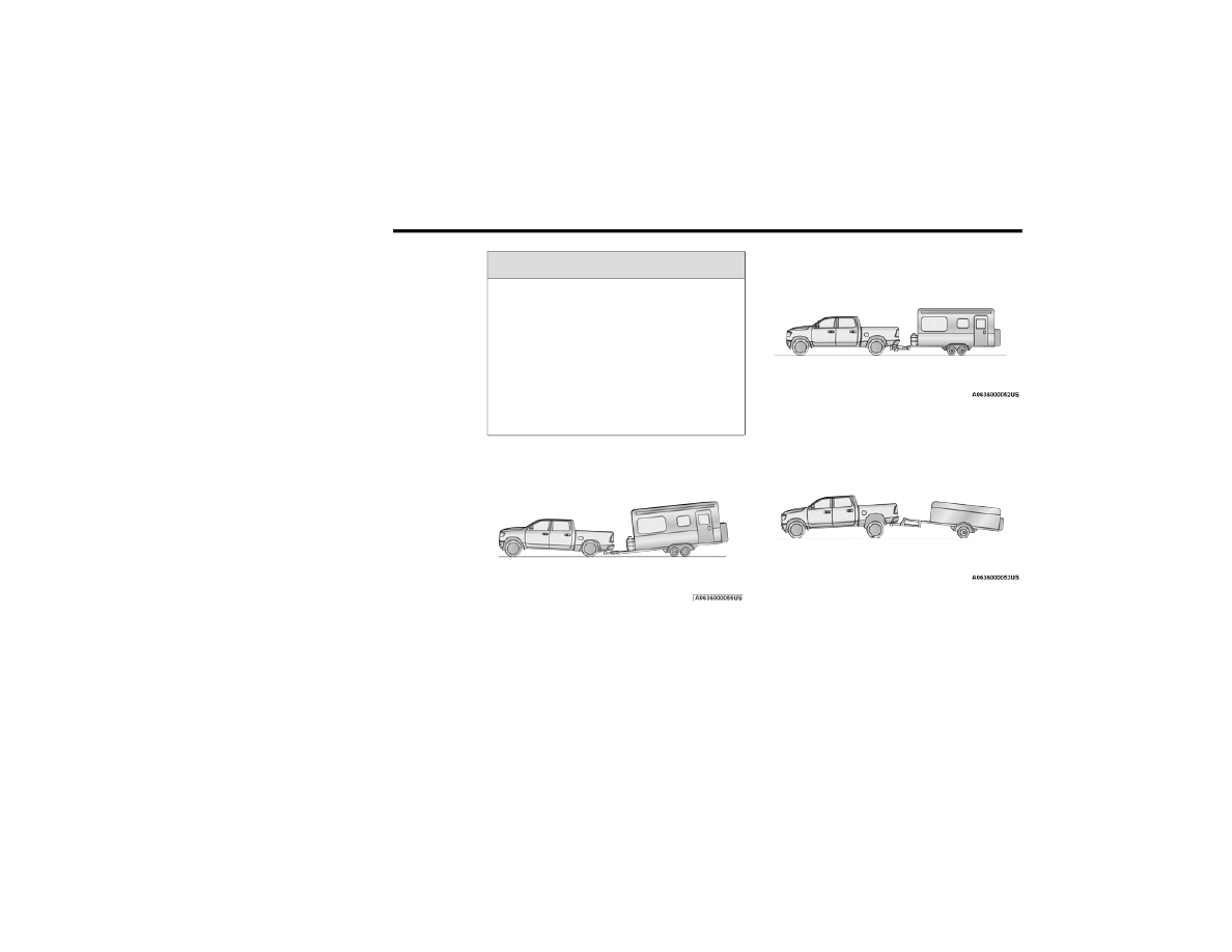
Without Weight-Distributing Hitch (Incorrect)

With Weight-Distributing Hitch (Correct)

Improper Adjustment Of Weight-Distributing Hitch 

(Incorrect)

WARNING!

An improperly adjusted weight distributing 

hitch system may reduce handling, stability 

and braking performance and could result 

in a collision.

Weight distributing systems may not be 

compatible with surge brake couplers. 

Consult with your hitch and trailer manufac

-

turer or a reputable Recreational Vehicle 

dealer for additional information.

-------------------------------------------------------------------------------------------------------------------------------------------------------------

STARTING AND OPERATING

203

Recommended Distribution Hitch Adjustment

1. Position the truck to be ready to connect to 

the trailer (do not connect the trailer).

2. Measure the height of the top of the front 

wheel opening on the fender to ground, this 

is height H1.

Measuring Height (H)

3. Attach the trailer to the vehicle without the 

weight distribution bars connected.

4. Measure the height of the top of the front 

wheel opening on the fender to ground, this 

is height H2.

5. Install and adjust the tension in the weight 

distributing bars per the manufacturers’ 

recommendations so that the height of the 

front fender is approximately (H2-H1)/

2+H1 (about 1/2 the difference between 

H2 and H1 above normal ride height [H1]).

6. Perform a visual inspection of the trailer 

and weight distributing hitch to confirm 

manufacturers’ recommendations have 

been met.

NOTE:

For all towing conditions, we recommend towing 

with TOW/HAUL mode engaged.

Fifth-Wheel Hitch

The fifth-wheel hitch is a special high platform 

with a coupling that mounts over the rear axle of 

the tow vehicle in the truck bed. It connects a 

vehicle and fifth-wheel trailer with a coupling 

king pin.
Your truck may be equipped with a fifth wheel 

hitch option. Refer to the separately provided 

fifth wheel hitch safety, care, assembly, and 

operating instructions.

Gooseneck Hitch

The gooseneck hitch employs a pivoted 

coupling arm which attaches to a ball mounted 

in the bed of a pickup truck. The coupling arm 

connects to the hitch mounted over the rear 

axle in the truck bed.

Measurement 

Example

Example 2500/

3500 Height (mm)

H1

1,030

H2

1,058

H2-H1

28

(H2-H1)/2

14

(H2-H1)/2 + H1

1,044

4

-------------------------------------------------------------------------------------------------------------------------------------------------------------

204

STARTING AND OPERATING


T

RAILER

 H

ITCH

 T

YPE


AND

 M

AXIMUM

 T

RAILER

 W

EIGHT

The following chart provides the industry standard for the maximum trailer weight a given trailer hitch class can tow and should be used to assist you 

in selecting the correct trailer hitch for your intended towing condition.

Trailer Hitch Classification Definitions

Class

Max. Trailer Hitch Industry Standards

Class I - Light Duty

2,000 lbs (907 kg)

Class II - Medium Duty

3,500 lbs (1,587 kg)

Class III - Heavy Duty

6,000 lbs (2,722 kg)

Class IV - Extra Heavy Duty

10,000 lbs (4,535 kg)

Fifth Wheel/Gooseneck

Greater than 10,000 lbs (4,535 kg)

Refer to the “Trailer Towing Weights (Maximum Trailer Weight Ratings)” for the Maximum Gross Trailer Weight (GTW) towable for your given drivetrain.
All trailer hitches should be professionally installed on your vehicle.

-------------------------------------------------------------------------------------------------------------------------------------------------------------

STARTING AND OPERATING

205

T

RAILER

 T

OWING

 W

EIGHTS

 (M

AXIMUM


T

RAILER

 W

EIGHT

 R

ATINGS

)   

NOTE:

For trailer towing information (maximum trailer 

weight ratings) refer to the following website 

addresses: 

ramtrucks.com/en/towing_guide/

ramtruck.ca (Canada)

rambodybuilder.com

T

RAILER

 A

ND

 T

ONGUE

 W

EIGHT


Never exceed the maximum tongue weight 

stamped on your bumper or trailer hitch.

Weight Distribution

Consider the following items when computing 

the weight on the rear axle of the vehicle:

The tongue weight of the trailer.

The weight of any other type of cargo or 

equipment put in or on your vehicle.

The weight of the driver and all passengers.

NOTE:

Remember that everything put into or on the 

trailer adds to the load on your vehicle. Also, addi

-

tional factory-installed options or dealer-installed 

options must be considered as part of the total 

load on your vehicle. For the maximum combined 

weight of occupants and cargo for your vehicle  

Ú

page 411.

T

OWING

 R

EQUIREMENTS


To promote proper break-in of your new vehicle 

drivetrain components, the following guidelines 

are recommended.

Perform the maintenance listed in the 

“Scheduled Servicing”  

Ú

page 353. When 

towing a trailer, never exceed the GAWR or 

GCWR ratings.

CAUTION!

Always load a trailer with 60% of the weight in 

the front of the trailer. This places 10% of the 

GTW on the tow hitch of your vehicle. Loads 

balanced over the wheels or heavier in the 

rear can cause the trailer to sway severely 

side to side which will cause loss of control of 

the vehicle and trailer. Failure to load trailers 

heavier in front is the cause of many trailer 

collisions.

CAUTION!

Do not tow a trailer at all during the first 

500 miles (805 km) the new vehicle is 

driven. The engine, axle or other parts could 

be damaged.

Then, during the first 500 miles (805 km) 

that a trailer is towed, do not drive over 

50 mph (80 km/h) and do not make starts 

at full throttle. This helps the engine and 

other parts of the vehicle wear in at the 

heavier loads.

4

-------------------------------------------------------------------------------------------------------------------------------------------------------------

206

STARTING AND OPERATING


(Continued)

Towing Requirements — Tires

Do not attempt to tow a trailer while using a 

compact spare tire.

Do not drive more than 50 mph (80 km/h) 

when towing while using a full size spare tire.

Proper tire inflation pressures are essential 

to the safe and satisfactory operation of your 

vehicle.

Check the trailer tires for proper tire inflation 

pressures before trailer usage.

Check for signs of tire wear or visible tire 

damage before towing a trailer.

For the proper tire replacement procedures. 

Replacing tires with a higher load carrying 

capacity will not increase the vehicle's GVWR 

and GAWR limits.

For further information  

Ú

page 406.

Towing Requirements — Trailer Brakes

Do not interconnect the hydraulic brake 

system or vacuum system of your vehicle 

with that of the trailer. This could cause inad

-

equate braking and possible personal injury.

An electronically actuated trailer brake 

controller is required when towing a trailer 

with electronically actuated brakes. When 

towing a trailer equipped with a hydraulic 

surge actuated brake system, an electronic 

brake controller is not required.

Trailer brakes are recommended for trailers 

over 1,000 lbs (453 kg) and required for 

trailers in excess of 2,000 lbs (907 kg).

WARNING!

Make certain that the load is secured in the 

trailer and will not shift during travel. When 

trailering cargo that is not fully secured, 

dynamic load shifts can occur that may be diffi

-

cult for the driver to control. You could lose 

control of your vehicle and have a collision.

When hauling cargo or towing a trailer, do 

not overload your vehicle or trailer. Over

-

loading can cause a loss of control, poor 

performance or damage to brakes, axle, 

engine, transmission, steering, suspension, 

chassis structure or tires.

Safety chains must always be used 

between your vehicle and trailer. Always 

connect the chains to the hook retainers of 

the vehicle hitch. Cross the chains under 

the trailer tongue and allow enough slack 

for turning corners.

Vehicles with trailers should not be parked 

on a grade. When parking, apply the 

parking brake on the tow vehicle. Put the 

tow vehicle transmission in PARK. For 

four-wheel drive vehicles, make sure the 

transfer case is not in NEUTRAL. Always, 

block or "chock" the trailer wheels.

GCWR must not be exceeded.

Total weight must be distributed between 

the tow vehicle and the trailer such that the 

following four ratings are not exceeded:

GVWR

GTW

GAWR

Tongue weight rating for the trailer 

hitch utilized.

WARNING!

 (Continued)

-------------------------------------------------------------------------------------------------------------------------------------------------------------

STARTING AND OPERATING

207

Integrated Trailer Brake Module — If 

Equipped 

Your vehicle may have an Integrated Trailer 

Brake Module (ITBM) for Electric and Electric 

Over Hydraulic (EOH) trailer brakes.

NOTE:

This module has been designed and verified 

with electric trailer brakes and new EOH 

systems. Some previous EOH systems may not 

be compatible with ITBM.

Integrated Trailer Brake Module (ITBM)

The user interface consists of the following:
Manual Brake Control Lever
Slide the manual brake control lever to the left 

to activate power to the trailer's electric brakes 

independent of the tow vehicle's brakes. If the 

manual brake control lever is activated while 

the brake is also applied, the greater of the two 

inputs determines the power sent to the trailer 

brakes.
The trailer and the vehicle’s stop lamps will 

come on when braking normally with the vehicle 

brake pedal. Only the trailer stop lamps will 

come on when the manual brake control lever is 

applied.
Trailer Brake Status Indicator Light
This light indicates the trailer electrical 

connection status.
If no electrical connection is detected after the 

ignition is turned on, pushing the GAIN adjustment 

button or sliding the manual brake control lever will 

display the GAIN setting for 10 seconds and the 

“Trailer Brake Status Indicator Light” will not be 

displayed.

WARNING!

Do not connect trailer brakes to your 

vehicle's hydraulic brake lines. It can over

-

load your brake system and cause it to fail. 

You might not have brakes when you need 

them and could have an accident.

Towing any trailer will increase your stop

-

ping distance. When towing, you should 

allow for additional space between your 

vehicle and the vehicle in front of you. 

Failure to do so could result in an accident.

CAUTION!

If the trailer weighs more than 1,000 lbs 

(453 kg) loaded, it should have its own 

brakes and they should be of adequate 

capacity. Failure to do this could lead to 

accelerated brake lining wear, higher brake 

pedal effort, and longer stopping distances.

1 — GAIN - Adjustment Button
2 — GAIN + Adjustment Button
3 — Manual Brake Control Lever

4

-------------------------------------------------------------------------------------------------------------------------------------------------------------

208

STARTING AND OPERATING


If a fault is detected in the trailer wiring or the 

Integrated Trailer Brake Module (ITBM), the 

“Trailer Brake Status Indicator Light” will flash.
GAIN Adjustment Buttons (+/-)
Pushing these buttons will adjust the brake 

control power output to the trailer brakes in 

0.5 increments. The GAIN setting can be 

increased to a maximum of 10 or decreased 

to a minimum of 0 (no trailer braking).
GAIN
The GAIN setting is used to set the trailer brake 

control for the specific towing condition and 

should be changed as towing conditions 

change. Changes to towing conditions include 

trailer load, vehicle load, road conditions and 

weather.
Adjusting GAIN

NOTE:

This should only be performed in a traffic-free 

environment at speeds of approximately 

20–25 mph (30–40 km/h).

1. Make sure the trailer brakes are in good 

working condition, functioning normally 

and properly adjusted. See a trailer dealer 

if necessary.

2. Hook up the trailer and make the electrical 

connections according to the trailer 

manufacturer's instructions.

3. When a trailer with electric/EOH brakes is 

plugged in, the trailer connected message 

should appear in the instrument cluster 

display (if the connection is not recognized 

by the ITBM, braking functions will not be 

available), the GAIN setting will illuminate 

and the correct type of trailer must be 

selected from the instrument cluster display 

options.

4. Push the UP or DOWN button on the 

steering wheel until “TRAILER TOW” 

appears on the screen.

5. Push the RIGHT arrow on the steering wheel 

to enter “TRAILER TOW”.

6. Push the UP or DOWN buttons until the 

Trailer Brake Type appears on the screen.

7. Push the RIGHT arrow and then push the UP 

or DOWN buttons until the proper Trailer 

Brake Type appears on the screen.

8. In a traffic-free environment, tow the trailer 

on a dry, level surface at a speed of 

20–25 mph (30–40 km/h) and squeeze 

the manual brake control lever completely.

9. If the trailer wheels lockup (indicated by 

squealing tires), reduce the GAIN setting; if 

the trailer wheels turn freely, increase the 

GAIN setting.

Repeat steps 8 and 9 until the GAIN setting is at 

a point just below trailer wheel lockup. If towing 

a heavier trailer, trailer wheel lockup may not be 

attainable even with the maximum GAIN setting 

of 10.

-------------------------------------------------------------------------------------------------------------------------------------------------------------

STARTING AND OPERATING

209

* The suggested selection depends and

may change depending on the customer 

preferences for braking performance. Condition 

of the trailer brakes, driving and road state may 

also affect the selection.
Display Messages
The trailer brake control interacts with the 

instrument cluster display. Display messages, 

along with a single chime, will be displayed 

when a malfunction is determined in the trailer 

connection, trailer brake control, or on the 

trailer  

Ú

page 90.

NOTE:

An aftermarket controller may be available 

for use with trailers with air or EOH trailer 

brake systems. To determine the type of 

brakes on your trailer and the availability of 

controllers, check with your trailer manufac

-

turer or dealer.

Removal of the ITBM will cause errors and it 

may cause damage to the electrical system 

and electronic modules of the vehicle. See an 

authorized dealer if an aftermarket module is 

to be installed.

Towing Requirements — Trailer Lights And 

Wiring

Whenever you pull a trailer, regardless of the 

trailer size, stoplights and turn signals on the 

trailer are required for motoring safety.
The Trailer Tow Package may include a four- and 

seven-pin wiring harness. Use a factory 

approved trailer harness and connector.

NOTE:

Do not cut or splice wiring into the vehicle’s 

wiring harness.

The electrical connections are all complete to 

the vehicle but you must mate the harness 

to a trailer connector. Refer to the following 

illustrations.

Light Electric

Heavy Electric

Light EOH

Heavy EOH

Type of Trailer Brakes

Electric Trailer Brakes

Electric Trailer Brakes

Electric over Hydraulic 

Trailer Brakes

Electric over Hydraulic 

Trailer Brakes

Load

*Under 10,000 lbs (4,536 kg) *Above 10,000 lbs (4,536 kg) *Under 10,000 lbs (4,536 kg) *Above 10,000 lbs (4,536 kg)

WARNING!

Connecting a trailer that is not compatible with 

the ITBM system may result in reduced or 

complete loss of trailer braking. There may be a 

increase in stopping distance or trailer instability 

which could result in personal injury.

CAUTION!

Connecting a trailer that is not compatible 

with the ITBM system may result in reduced 

or complete loss of trailer braking. There may 

be a increase in stopping distance or trailer 

instability which could result in damage to 

your vehicle, trailer, or other property.

4

-------------------------------------------------------------------------------------------------------------------------------------------------------------

210

STARTING AND OPERATING


NOTE:

Disconnect trailer wiring connector from the 

vehicle before launching a boat (or any other 

device plugged into vehicle’s electrical 

connect) into water.

Be sure to reconnect once clear from water 

area.

Four-Pin Connector

Seven-Pin Connector

Trailer Light Check
This feature will run the trailer lights through a 

sequence to check the trailer light function. It is 

available in the instrument cluster under the 

Trailer Tow menu  

Ú

page 94.

When activated the feature will enable all of the 

exterior lights sequentially for up to five minutes 

allowing time to walk around and verify 

functionality. The following exterior lights will 

remain on for the entirety of the sequence:

Park/Running Lamps

Side Marker Lamps (if equipped)

License Lamp

Signature Lamp (if equipped)

Low Beams

Fog Lamps (if equipped)

Daytime Running Lamps

During this time the following lights will 

sequence, each activating for three seconds:

1. Brake and CHMSL (third brake light)

2. Left turn signal

3. Right turn signal

4. Reverse Lamps

5. High Beam

1 — Ground
2 — Park
3 — Left Stop/Turn
4 — Right Stop/Turn

1 — Backup Lamps
2 — Running Lamps
3 — Left Stop/Turn
4 — Ground
5 — Battery
6 — Right Stop/Turn
7 — Electric Brakes

-------------------------------------------------------------------------------------------------------------------------------------------------------------

STARTING AND OPERATING

211

This light check sequence will continue for a 

total of five minutes.
The sequence will only activate if the following 

conditions are met:

Vehicle is equipped with the Trailer Tow 

Package

Vehicle is in PARK

Vehicle is not in motion

Ignition in ACC or RUN

Remote start is inactive

Brakes are not applied

Left turn signal is not applied

Right turn signal not applied

Hazard switch is not applied

The sequence will cancel if any of the following 

conditions occur:

Brakes are applied

Vehicle is shifted from PARK

Vehicle is no longer stationary

Left turn signal activated from stalk

Right turn signal is activated from stalk

Hazard switch is activated

Any button on the key fob is pushed

Ignition button is pushed

High Beam stalk position is changed

Sequence is canceled in the instrument 

cluster

T

OWING

 T

IPS


Before setting out on a trip, practice turning, 

stopping, and backing up the trailer in an area 

located away from heavy traffic.

Automatic Transmission

The DRIVE range can be selected when towing. 

The transmission controls include a drive 

strategy to avoid frequent shifting when towing. 

However, if frequent shifting does occur while in 

DRIVE, select TOW/HAUL mode or select a lower 

gear range (using the Electronic Range Select 

(ERS) shift control).

NOTE:

Using TOW/HAUL mode or selecting a lower 

gear range (using the ERS shift control) while 

operating the vehicle under heavy loading 

conditions will improve performance and 

extend transmission life by reducing excessive 

shifting and heat build-up. This action will also 

provide better engine braking.

Six-Speed Automatic Transmission Only
When towing a loaded trailer up steep grades 

at low speeds (20 mph [32 km/h] or below), 

holding your vehicle in FIRST gear (using the 

ERS shift control) can help to avoid 

transmission overheating.
If you regularly tow a trailer for more than 

45 minutes of continuous operation, then 

change the automatic transmission fluid and 

filter(s) as specified for "police, taxi, fleet, or 

frequent trailer towing."  

Ú

page 354.

NOTE:

Check the automatic transmission fluid level 

before towing (Six-speed automatic only).

4

-------------------------------------------------------------------------------------------------------------------------------------------------------------

212

STARTING AND OPERATING


Tow/Haul Mode

To reduce potential for automatic transmission 

overheating, activate TOW/HAUL mode when 

driving in hilly areas, or select a lower gear 

range (using the Electronic Range Select (ERS) 

shift control) on more severe grades.

Cruise Control — If Equipped

Do not use on hilly terrain or with heavy 

loads.

When using the Cruise Control, if you experi

-

ence speed drops greater than 10 mph 

(16 km/h), disengage until you can get back 

to cruising speed.

Use Cruise Control in flat terrain and with 

light loads to maximize fuel efficiency.

SNOWPLOW — IF EQUIPPED

Snowplow Prep Packages are available as a 

factory installed option. These packages 

include components necessary to equip your 

vehicle with a snowplow.

NOTE:

Before installation of a snowplow it is highly 

recommended that the owner/installer obtain 

and follow the recommendations contained 

within the current Body Builders Guide. See an 

authorized dealer, installer or snowplow manu

-

facturer for this information. There are unique 

electrical systems that must be connected to 

properly ensure operator safety and prevent 

overloading vehicle systems.

B

EFORE

 P

LOWING

Check the hydraulic system for leaks and 

proper fluid level.

Check the mounting bolts and nuts for proper 

tightness.

Check the runners and cutting edge for 

excessive wear. The cutting edge should be 

¼ to ½ inches (6 cm to 1.2 cm) above ground 

in snow plowing position.

Check that snowplow lighting is connected 

and functioning properly.

S

NOWPLOW

 P

REP

 P

ACKAGE

 M

ODEL


A

VAILABILITY

For Information about snowplow applications 

visit www.ramtrucks.com or refer to the current 

Body Builders Guide.

1. The maximum number of occupants in the 

truck should not exceed two.

2. The total GVWR or the Front GAWR or the 

Rear GAWR should never be exceeded.

3. Cargo capacity will be reduced by the 

addition of options or passengers, etc.

WARNING!

Attaching a snowplow to this vehicle could 

adversely affect performance of the airbag 

system in a collision. Do not expect that the 

airbag will perform as described earlier in this 

manual.

CAUTION!

The “Lamp Out” indicator could illuminate if 

exterior lamps are not properly installed.

-------------------------------------------------------------------------------------------------------------------------------------------------------------

STARTING AND OPERATING

213

The loaded vehicle weight, including the 

snowplow system, all aftermarket accessories, 

driver, passengers, options, and cargo, must 

not exceed either the Gross Vehicle Weight 

Rating (GVWR) or Gross Axle Weight Rating 

(GAWR). These weights are specified on the 

Safety Compliance Certification Label on the 

driver's side door opening.

NOTE:

Detach the snowplow when transporting 

passengers.

Vehicle front end wheel alignment was 

set to specifications at the factory without 

consideration for the weight of the plow.

Front end toe-in should be checked and reset 

if necessary at the beginning and end of the 

snowplow season. This will help prevent uneven 

tire wear.
The blade should be lowered whenever the 

vehicle is parked.
Maintain and operate your vehicle and snowplow 

equipment following the recommendations 

provided by the specific snowplow manufacturer.

O

VER

 T

HE

 R

OAD

 O

PERATION

 W

ITH


S

NOWPLOW

 A

TTACHED

The blade restricts air flow to the radiator and 

causes the engine to operate at higher than 

normal temperatures. Therefore, when 

transporting the plow, angle the blade completely 

and position it as low as road or surface 

conditions permit. Do not exceed 40 mph 

(64 km/h). The operator should always maintain 

a safe stopping distance and allow adequate 

passing clearance.

O

PERATING

 T

IPS

Under ideal snow plowing conditions, 20 mph 

(32 km/h) should be maximum operating 

speed. The operator should be familiar with the 

area and surface to be cleaned. Reduce speed 

and use extreme caution when plowing 

unfamiliar areas or under poor visibility.

G

ENERAL

 M

AINTENANCE

Snowplows should be maintained in 

accordance with the plow manufacturer's 

instructions.
Keep all snowplow electrical connections and 

battery terminals clean and free of corrosion.
When plowing snow, to avoid transmission and 

drivetrain damage, the following precautions 

should be observed.

Operate with transfer case in 4L when 

plowing small or congested areas where 

speeds are not likely to exceed 15 mph 

(24 km/h). At higher speeds operate in 

4WD High.

Vehicles with automatic transmissions 

should use 4WD Low range when plowing 

deep or heavy snow for extended periods of 

time to avoid transmission overheating.

Do not shift the transmission unless the 

engine has returned to idle and wheels have 

stopped. Make a practice of stepping on the 

brake pedal while shifting the transmission.

4

-------------------------------------------------------------------------------------------------------------------------------------------------------------

214

STARTING AND OPERATING


RECREATIONAL TOWING (BEHIND MOTORHOME) 

T

OWING

 T

HIS

 V

EHICLE

 B

EHIND

 A

NOTHER

 V

EHICLE

NOTE:

When towing your vehicle, always follow applicable state and provincial laws. Contact state and provincial Highway Safety offices for additional details.

Towing Condition

Wheels OFF The 

Ground

Two-Wheel Drive 

Models

Four-Wheel Drive Models

Flat Tow

NONE

NOT ALLOWED

See Instructions

Automatic transmission in PARK

Transfer case in NEUTRAL (N)

Tow in forward direction

Dolly Tow

Front

NOT ALLOWED

NOT ALLOWED

Rear

OK

NOT ALLOWED

On Trailer

ALL

OK

OK

-------------------------------------------------------------------------------------------------------------------------------------------------------------

STARTING AND OPERATING

215

(Continued)

R

ECREATIONAL

 T

OWING

 — T

WO

-W

HEEL


D

RIVE

 M

ODELS

DO NOT flat tow this vehicle. Damage to the 

drivetrain will result.
Recreational towing (for two-wheel drive 

models) is allowed ONLY if the rear wheels are 

OFF the ground. This may be accomplished 

using a tow dolly or vehicle trailer. If using a tow 

dolly, follow this procedure:

1. Properly secure the dolly to the tow vehicle, 

following the dolly manufacturer's 

instructions.

2. Drive the rear wheels onto the tow dolly.

3. Firmly apply the parking brake. Place 

automatic transmission in PARK.

4. Properly secure the rear wheels to the 

dolly, following the dolly manufacturer's 

instructions.

5. Turn the ignition to the OFF position and 

remove the key fob.

6. Install a suitable clamping device, designed 

for towing, to secure the front wheels in the 

straight position.

R

ECREATIONAL

 T

OWING

 — 

F

OUR

-W

HEEL

 D

RIVE

 M

ODELS

NOTE:

Both the manual shift and electronically shifted 

transfer cases must be shifted into N (Neutral) 

for recreational towing. Automatic transmis

-

sions must be shifted into PARK for recreational 

towing. Refer to the following for the proper 

transfer case N (Neutral) shifting procedure for 

your vehicle.

CAUTION!

Towing with the rear wheels on the ground 

will cause severe transmission damage. 

Damage from improper towing is not 

covered under the New Vehicle Limited 

Warranty.

Do not disconnect the driveshaft because 

fluid may leak from the transmission, 

causing damage to internal parts.

CAUTION!

DO NOT dolly tow any four-wheel drive 

vehicle. Towing with only one set of wheels 

on the ground (front or rear) will cause 

severe transmission and/or transfer case 

damage. Tow with all four wheels either ON 

the ground, or OFF the ground (using a 

vehicle trailer).

Tow only in the forward direction. Towing 

this vehicle backwards can cause severe 

damage to the transfer case.

Before recreational towing, the transfer 

case must be in NEUTRAL. To be certain the 

transfer case is fully in NEUTRAL, perform 

the procedure outlined under “Shifting Into 

NEUTRAL”. Internal transmission damage 

will result, if the transfer case is not in 

NEUTRAL during towing.

The transmission must be placed in PARK 

for recreational towing.

Towing this vehicle in violation of the above 

requirements can cause severe transmis

-

sion and/or transfer case damage. Damage 

from improper towing is not covered under 

the New Vehicle Limited Warranty.

4

-------------------------------------------------------------------------------------------------------------------------------------------------------------

216

STARTING AND OPERATING


Shifting Into N (Neutral) 

Use the following procedure to prepare your 

vehicle for recreational towing.

1. Bring the vehicle to a complete stop on 

level ground, with the engine running. 

Firmly apply the parking brake.

2. Shift the transmission to NEUTRAL.

3. Press and hold the brake pedal.

4. Shift the transfer case into N (Neutral):

With manual shift transfer case, shift the 

transfer case lever into N (Neutral).

With electronically shifted transfer

case, push and hold the transfer case

N (Neutral) button. Some models have a 

small, recessed "N" button (at the center 

of the transfer case switches) that must be 

pressed using a ballpoint pen or similar 

object. Other models have a rectangular 

N (Neutral) switch, below the rotary 

transfer case control knob. The N (Neutral) 

indicator light will blink while the shift is in 

progress. The light will stop blinking (stay 

on solid) when the shift to N (Neutral) is 

complete. After the shift is completed and 

the N (Neutral) light stays on, release the 

N (Neutral) button.

5. Release the parking brake.

6. Shift the transmission into REVERSE.

7. Release the brake pedal for five seconds 

and ensure that there is no vehicle 

movement.

8. Repeat steps 6 and 7 with automatic 

transmission in DRIVE.

9. Shift the transmission to NEUTRAL. Firmly 

apply the parking brake. Turn off the engine. 

For vehicles with Keyless Enter-N-Go, push 

and hold the ENGINE START/STOP button 

until the engine shuts off.

10. Shift the transmission into PARK.

11. Place the ignition in the OFF mode, and 

remove the key fob.

12. Attach the vehicle to the tow vehicle using a 

suitable tow bar.

13. Release the parking brake.

Do not disconnect the rear driveshaft 

because fluid will leak from the transfer 

case, causing damage to internal parts.

Do not use a bumper-mounted clamp-on 

tow bar on your vehicle. The bumper face 

bar will be damaged.

WARNING!

You or others could be injured or killed if you 

leave the vehicle unattended with the transfer 

case in the N (NEUTRAL) position without first 

fully engaging the parking brake. The transfer 

case N (NEUTRAL) position disengages both 

the front and rear driveshafts from the 

powertrain, and will allow the vehicle to 

roll, even if the automatic transmission is

in PARK (or manual transmission is in gear). 

The parking brake should always be applied 

when the driver is not in the vehicle.

CAUTION!

 (Continued)

CAUTION!

It is necessary to follow these steps to be 

certain that the transfer case is fully in 

NEUTRAL (N) before recreational towing to 

prevent damage to internal parts.

-------------------------------------------------------------------------------------------------------------------------------------------------------------

STARTING AND OPERATING

217

NOTE:

With electronically shifted transfer case: 

Steps 2 through 3 are requirements that 

must be met before pushing the N (Neutral) 

button, and must continue to be met until the 

shift has been completed. If any of these 

requirements are not met before pushing the 

N (Neutral) button or are no longer met 

during the shift, the N (Neutral) indicator light 

will flash continuously until all requirements 

are met or until the N (Neutral) button is 

released.

The ignition must be in the ON/RUN mode for 

a shift to take place and for the position indi

-

cator lights to be operable. If the ignition is 

not in the ON/RUN mode, the shift will not 

take place and no position indicator lights will 

be on or flashing.

A flashing N (Neutral) position indicator light 

indicates that shift requirements have not 

been met.

Shifting Out Of N (Neutral) 

Use the following procedure to prepare your 

vehicle for normal usage:

1. Bring the vehicle to a complete stop, 

leaving it connected to the tow vehicle.

2. Firmly apply the parking brake.

3. Press and hold the brake pedal.

4. Start the engine, and shift the transmission 

into NEUTRAL.

With manual shift transfer case, shift the 

transfer case lever to the desired position.

With electronically shifted transfer case 

with rotary selector switch, push and hold 

the transfer case N (Neutral) button until 

the N (Neutral) indicator light turns off. 

After the N (Neutral) indicator light turns 

off, release the N (Neutral) button. After 

the N (Neutral) button has been released, 

the transfer case will shift to the position 

indicated by the selector switch.

With electronically shifted transfer case 

with push-button selector switch, push 

and hold the switch for the desired 

transfer case position, until the N 

(Neutral) indicator light turns off and the 

desired position indicator light turns on.

NOTE:

When shifting the transfer case out of 

N (Neutral), turning the engine off is not 

required, but may be helpful to avoid gear clash. 

With 8-speed automatic transmission, the 

engine must remain running, since turning the 

engine off will shift the transmission to PARK 

(and the transmission must be in NEUTRAL for 

the transfer case to shift out of NEUTRAL).

5. Turn the engine off. Shift automatic 

transmission into PARK. On 8-speed 

transmissions the shifter will automatically 

select PARK when the engine is turned off.

6. Release the brake pedal.

7. Disconnect vehicle from the tow vehicle.

8. Start the engine.

9. Press and hold the brake pedal.

10. Release the parking brake.

11. Shift the transmission into gear, release the 

brake pedal, and check that the vehicle 

operates normally.

4

-------------------------------------------------------------------------------------------------------------------------------------------------------------


Content      ..     11      12      13      14     ..