Acura RSX Honda Integra. Manual - part 406
−
−
−
−
−
−
−
−
YES
NO
YES
NO
YES
NO
YES
NO
21-31
21-31
ECT Sensor Circuit Troubleshooting
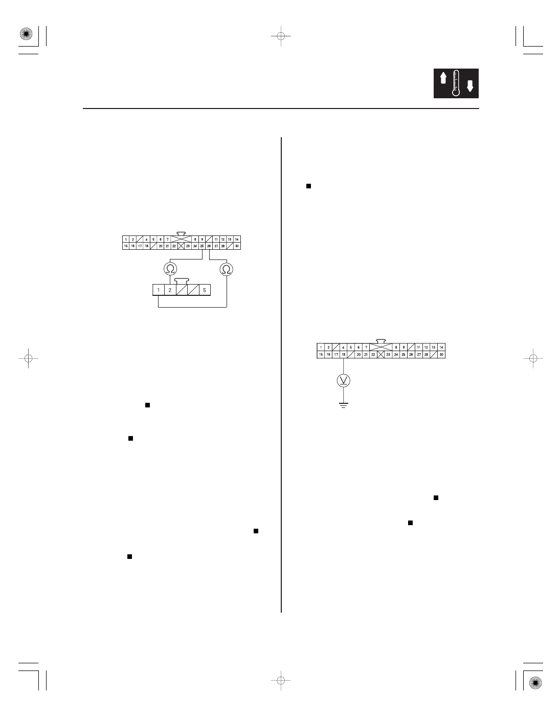
CLIMATE CONTROL UNIT 30P CONNECTOR
RECIRCULATION CONTROL MOTOR 5P CONNECTOR
GRN/WHT
GRN/YEL
GRN/WHT
GRN/YEL
CLIMATE CONTROL UNIT 30P CONNECTOR
RED/WHT
10. Turn the ignition switch OFF.
11. Check for continuity between the following
terminals of the climate control unit 30P connector
and the recirculation control motor 5P connector.
30P:
5P:
No. 25
No. 2
No. 26
No. 1
Check for loose wires or poor connections at
the climate control unit 30P connector and at
recirculation control motor 5P connector. If the
connections are good, substitute a known-good
climate control unit, and recheck. If the symptom/
indication goes away, replace the original climate
control unit.
Repair any open in the wire(s) between the
climate control unit and the recirculation control
motor.
12. Remove the recirculation control motor (see page
21-47).
13. Check the recirculation control linkage and doors
for smooth movement.
Replace the recirculation control motor.
Repair the recirculation control linkage or
doors.
1. Check the malfunction indicator lamp (MIL).
Refer to the powertrain DTCs (see page 11-3).
Go to step 2.
2. Turn the ignition switch OFF.
3. Disconnect the ECT sensor 2P connector.
4. Disconnect the climate control unit 30P connector.
5. Turn the ignition switch ON (II).
6. Measure the voltage between the No. 18 terminal
of the climate control unit 30P connector and body
ground.
Check for loose wires or poor connections at
the climate control unit 30P connector and at the
ECT sensor 2P connector. If the connections are
good, substitute a known-good climate control unit,
and recheck. If the symptom/indication goes away,
replace the original climate control unit.
Repair open in the wire between the climate
control unit and the ECT sensor.
Wire side of female terminals
Wire side of female terminals
Wire side of female terminals
Is ther e continuity?
Do the r ecir culation contr ol linkage and door s
move smoothly?
Does the malf unction indicator lamp come on?
Is ther e about 5 V ?
05/06/27 18:04:46 61S6M040_210_0032