Acura RSX Honda Integra. Manual - part 304


  Index      Acura     Acura RSX Honda Integra - service repair manual 2002-2006 year


Search            


Content   ..  302  303  304  305   ..


Acura RSX Honda Integra. Manual - part 304


01

02

01

S6M6A02E10411239511KCAT00

Special Tools Required

14-341

Bearing Installation

A

B

A

B: 0

7 mm (0

0.28 in.)

A

• Attachment, 78 x 90 mm 07GAD-SD40101
• Driver 07749-0010000
• Attachment, 42 x 47 mm 07746-0010300

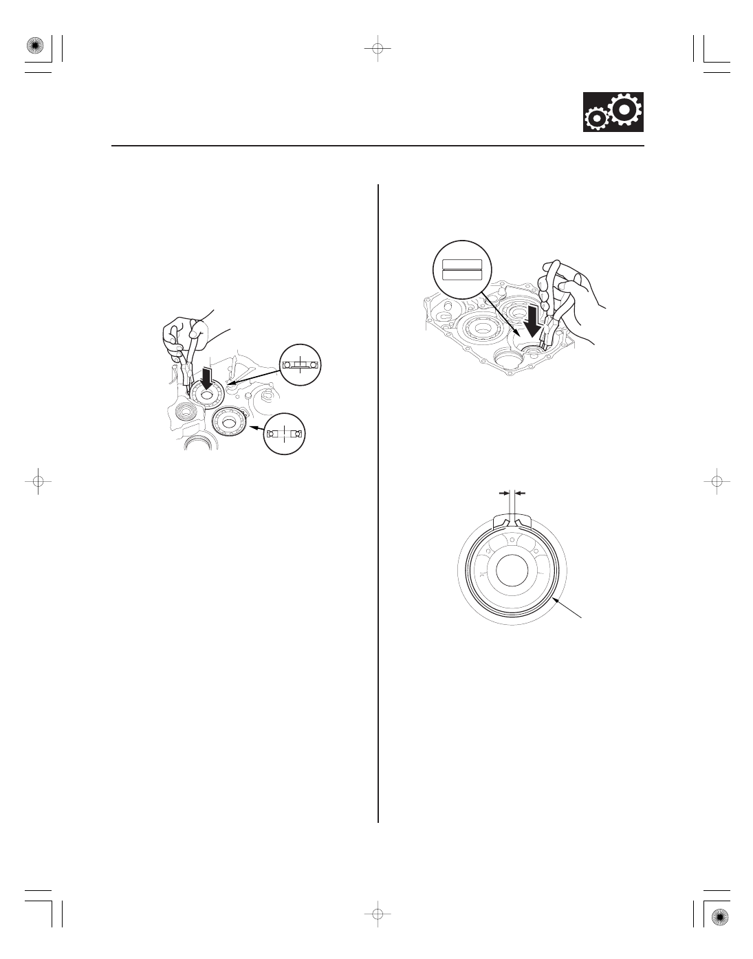
1. Install the bearings in the direction shown.

2. Expand each snap ring with the snap ring pliers,

and install the mainshaft bearing (A) and
countershaft bearing (B) part-way into the housing.

3. Release the pliers, then push the bearing down into

the housing until the snap ring snaps in place
around it.

4. Expand the snap ring of the idler gear shaft (A) with

the snap ring pliers, and install the bearing part-
way into the housing.

5. Release the pliers, then push the bearing down into

the housing until the snap ring snaps in place
around it.

6. After installing the bearings verify that the snap

rings (A) are seated in the bearing and housing
grooves, and that the ring end gaps (B) are correct.

7. Install the idler shaft.

05/06/27 17:58:58 61S6M040_140_0342

01

02

03

04

S6M6A02E10400012271KDAT00

Removal

Installation

14-342

Transmission Housing

Reverse Idler Gear Removal and Installation

A

B

D

C

D

C

A

B

C

F

E

6 x 1.0 mm
12 N·m
(1.2 kgf·m,
8.7 lbf·ft)

1. Remove the bolt (A) securing the reverse idler gear

shaft holder.

2. Install a 5 x 0.8 mm bolt (B) in the reverse idler gear

shaft, and pull it to remove the reverse idler gear
shaft (C) and gear shaft holder (D) together.

3. Remove the reverse idler gear.

1. Install the reverse idler gear in the transmission

housing.

2. Lightly coat the reverse idler gear shaft (A), needle

bearing (B), and new O-rings (C) with lithium
grease.

3. Assemble the new O-rings and needle bearing on

the reverse idler gear shaft, then install the reverse
idler gear shaft in the reverse idler gear shaft
holder (D). Align the D-shaped cut out (E) of the
shaft with the D-shaped area (F) of the holder.

4. Install the reverse idler gear shaft/holder assembly

on the transmission housing.

05/06/27 17:58:58 61S6M040_140_0343

*01

S6M6A02E10480139301KAAT00

Exploded View

14-343

Valve Body

Valve Body and ATF Strainer Removal

6 x 1.0 mm
Two Bolts

ATF STRAINER

O-RING

6 x 1.0 mm
13 Bolts

ATF FEED PIPE,
8 x 220 mm

6 x 1.0 mm
One Bolts

REGULATOR
VALVE BODY

6 x 1.0 mm
Seven Bolts

ATF FEED PIPE,
8 x 198 mm

ATF JOINT
PIPES

O-RING

STATOR SHAFT STOP

DOWEL PIN

REGULATOR
SEPARATOR
PLATE

STATOR SHAFT

SERVO BODY

DOWEL PIN

SERVO SEPARATOR
PLATE

8 x 1.25 mm
Three Bolts

COOLER CHECK
VALVE

MAIN VALVE BODY

ATF PUMP DRIVEN
GEAR SHAFT

ATF PUMP DRIVEN
GEAR

MAIN
SEPARATOR
PLATE

DOWEL PIN

ATF PUMP DRIVE
GEAR

TORQUE CONVERTER HOUSING

COOLER CHECK
VALVE SPRING

COOLER CHECK
VALVE (BALL)

(cont’d)

Replace.

Replace.

05/06/27 17:58:59 61S6M040_140_0344

01

14-344

Valve Body

Valve Body and ATF Strainer Removal (cont’d)

B

A

NOTE: Refer to the Exploded View as needed during the
following procedure.

1. Remove the ATF feed pipes from the regulator

valve body, and servo body.

2. Remove the ATF strainer (two bolts).

3. Remove the servo body (13 bolts), then remove the

separator plate and dowel pins (two).

4. Remove the ATF joint pipes (one bolt) from the

regulator valve body.

5. Remove the regulator valve body (seven bolts).

6. Remove the stator shaft and stator shaft stop.

7. Remove the regulator separator plate and dowel

pins (two).

8. Remove the cooler check valve spring:

• 2002 model (transmission number 1000001-

1006166): Remove the cooler check valve spring
from the main valve body, then remove the main
valve body (three bolts). Do not let the check
balls and cooler check valve (ball) fall out.

• 2002 model (transmission number 1006167 or

later), and 2003-2006 models: Remove the cooler
check valve spring and cooler check valve from
the main valve body, then remove the main valve
body (three bolts). Do not let the check balls fall
out.

9. Remove the ATF pump driven gear shaft, then

remove the ATF pump gears.

10. Remove the main separator plate and dowel pins

(two).

11. Clean the inlet opening (A) of the ATF strainer (B)

thoroughly with compressed air, then check that it
is in good condition and that the inlet opening is
not clogged.

12. Test the ATF strainer by pouring clean ATF through

the inlet opening, and replace it if it is clogged or
damaged.

13. Remove the O-rings from the stator shaft and ATF

strainer. Install a new O-rings when installing the
valve bodies.

05/06/27 17:58:59 61S6M040_140_0345


Content   ..  302  303  304  305   ..