Acura RSX Honda Integra. Manual - part 225
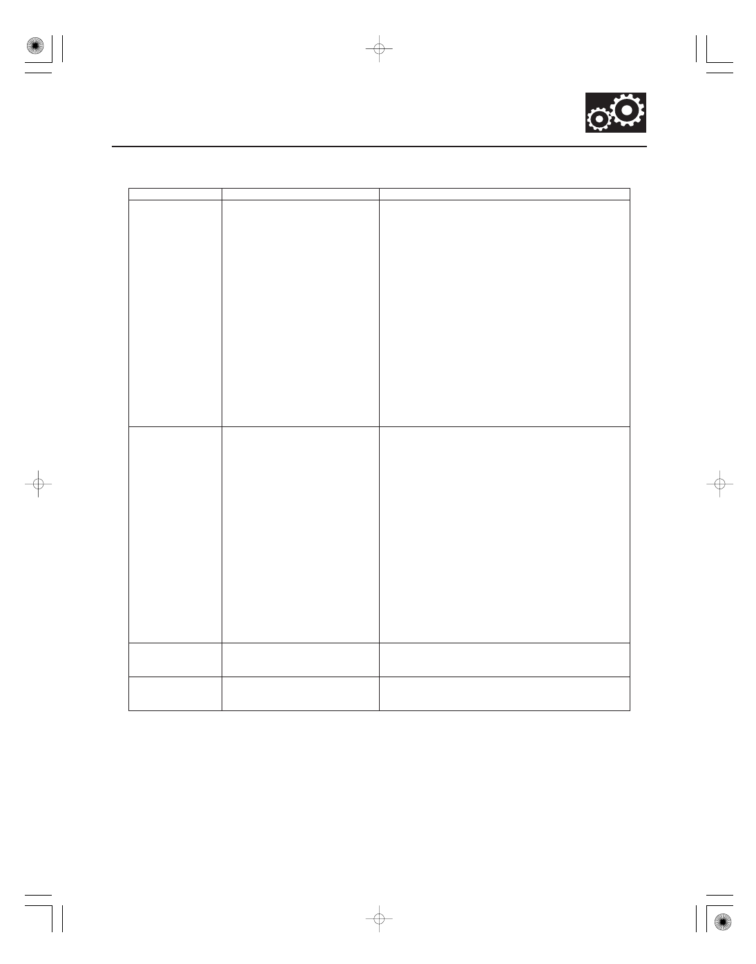
Symptom
Probable cause(s)
Notes
14-25
•
•
•
•
•
•
•
•
•
•
•
•
•
Excessive shock or
flares on 4-5
upshift or 5-4
downshift
1.
2.
3.
4.
5.
6.
7.
A/T clutch pressure control
solenoid valve B defective
A/T clutch pressure control
solenoid valve C defective
Foreign material in separator
plate orifice
4th accumulator defective
5th accumulator defective
4th clutch defective
5th clutch defective
Check the D indicator, and check for loose connectors.
Inspect the solenoid valve filter/gasket and O-rings
for wear and damage, and inspect the solenoid
valves for seizure.
Check the 4th and 5th clutch pressures.
Inspect the clutch piston, clutch piston check valve,
and O-rings. Check the spring retainer and retainer
seal for wear and damage. Inspect the clutch-end-
plate-to-top-disc clearance. If the clearance is out of
tolerance, inspect the clutch discs and plates for wear
and damage. If the discs are worn or damaged,
replace the discs as a set. Inspect the clutch waved-
plate height. If the height is out of tolerance, replace
the waved-plate. If the discs and plates are OK, adjust
the clearance with the clutch end plate.
Inspect the 5th clutch feed pipe. If the 5th clutch feed
pipe is scored, replace it and O-ring under the feed
pipe guide.
Replace the mainshaft if the bushing for the 5th
clutch feed pipe is loose or damaged.
Noise from
transmission in all
shift lever
positions
1.
2.
ATF pump worn or binding
Mainshaft bearing,
countershaft bearing or
secondary shaft bearing
defective
Improper alignment of ATF pump and torque
converter housing may cause ATF pump seizure. The
symptoms are mostly an rpm-related ticking noise or
a high pitched squeak.
Be careful not to damage the torque converter
housing when replacing the main ball bearing. You
may also damage the ATF pump when you torque
down the main valve body. This will result in ATF
pump seizure if not detected. Use the proper tools.
Install the main seal flush with the torque converter
housing. If you push it into the torque converter
housing until it tops out, it will block the fluid return
passage and result in damage.
Inspect the ATF strainer is clogged with particles of
steel or aluminum. If the ATF strainer is clogged,
replace it, and clean the torque converter, cooler, and
lines.
Inspect the mainshaft and countershaft for wear or
damage.
Vehicle does not
accelerate above
31 mph (50 km/h)
Torque converter one-way clutch
defective
Replace the torque converter.
Vibration in all
shift lever
positions
Drive plate defective or
transmission misassembled
Check for a misinstalled/damaged drive plate.
Set idle rpm in gear to the specified idle speed. If still
no good, adjust the engine and transmission mounts.
(cont’d)
05/06/27 17:48:18 61S6M040_140_0026