Acura RSX Honda Integra. Manual - part 190
−
*04
*05
11
*06
−
−
Canister System Leak Test
YES
NO
11-466
EVAP System
DTC Troubleshooting (cont’d)
A
A
B
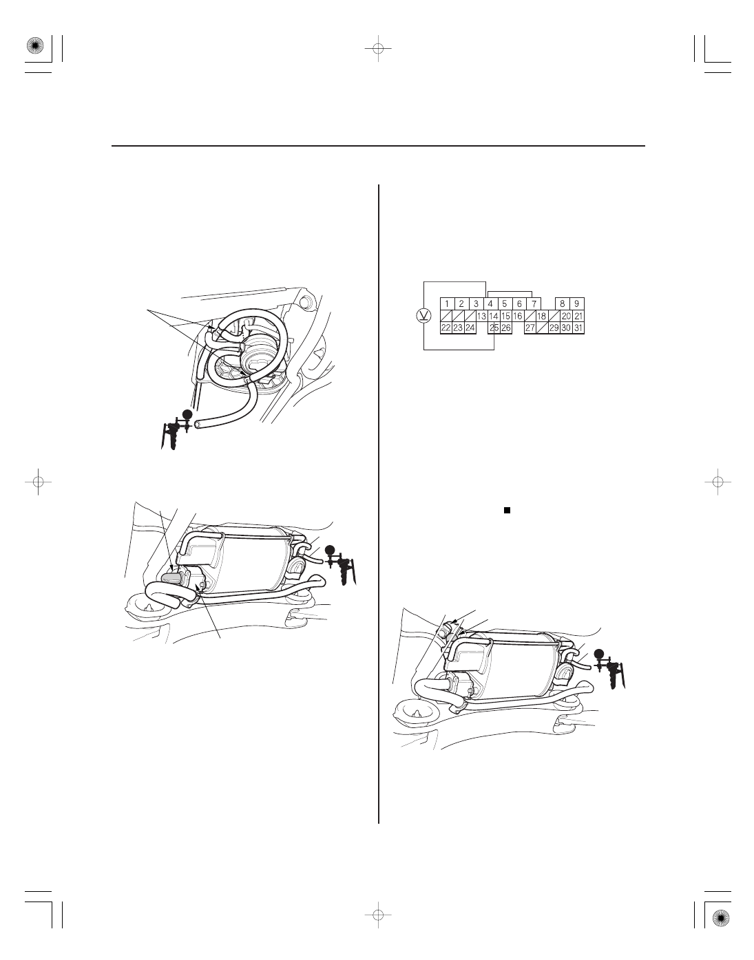
ECM/PCM CONNECTOR E (31P)
SG3 (PNK)
FTP (LT GRN)
A
B
27. Turn the ignition switch OFF.
28. Connect 2 three-way T-fittings (A) into the hose
from the EVAP canister to the EVAP two way valve.
Connect the FTP sensor to one of the T-fittings and
the vacuum pump/gauge, 0
30 in.Hg, to the other.
29. Remove the vent hose from the EVAP canister vent
shut valve (A), and cap the port (B) to seal the fresh
air vent for the EVAP canister.
30. Turn the ignition switch ON (II).
31. While monitoring FTP sensor voltage with the HDS,
or measuring voltage between ECM/PCM
connector terminals E4 and E14, slowly pump the
vacuum pump.
32. Continue to pump until the voltage drops to about
1.5 V. Make sure your vacuum pump has no leak.
33. Monitor the voltage for 20 seconds.
Inspect the EVAP canister vent shut valve
line and connections.
Go to step 34.
34. Turn the ignition switch OFF.
35. Disconnect the quick-connect fitting (A) from the
EVAP canister, and plug the canister port (B).
36. Turn the ignition switch ON (II).
Wire side of female terminals
Does the voltage dr op to 1.5 V and hold f or at
least 20 seconds?
05/06/27 17:44:53 61S6M040_110_0466