Acura RSX Honda Integra. Manual - part 179


  Index      Acura     Acura RSX Honda Integra - service repair manual 2002-2006 year


Search            


Content   ..  177  178  179  180   ..


Acura RSX Honda Integra. Manual - part 179


01

S6M6AALK72100090442FAAT00

DTC P0442:

DTC P0456:

Special Tools Required

YES

NO

YES

NO

YES

NO

11-422

EVAP System

DTC Troubleshooting

A

B

C

EVAP System Small Leak

Detected
(2005-2006 models)

EVAP System Very Small Leak

Detected
(2005-2006 models)

The fuel system is designed to allow specified
maximum vacuum and pressure conditions. Do not
deviate from the vacuum and pressure tests as
indicated in these procedures. Excessive pressure/
vacuum would damage the EVAP components or
cause eventual fuel tank failure.

• Vacuum/pressure gauge, 0

4 in.Hg, 07JAZ-001000B

• Vacuum pump/gauge, 0

30 in.Hg, Snap-on YA4000A

or equivalent, commercially available

NOTE: Fresh fuel has a higher volatility that will create
greater pressure/vacuum. The optimum condition for
testing is less than a full tank of fresh fuel. If possible, to
assist in leak detection, add 1 gallon of fresh fuel to the
tank (as long as it will not fill the tank) just before
starting these procedures.

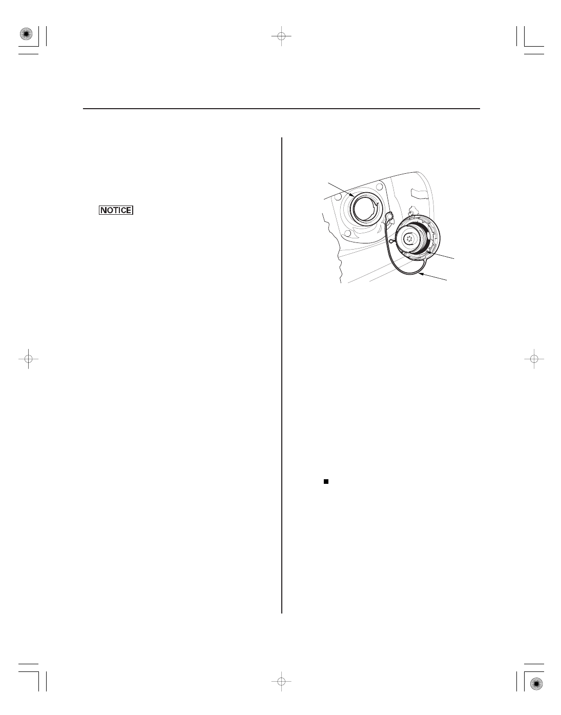
1. Check the fuel fill cap (the cap must say ‘‘Tighten

click’’). It should turn 1/4 turn after it’s tight, then it
clicks.

Go to step 2.

Replace or tighten the cap, then go to step 22.

2. Check the fuel fill cap seal (A) and the fuel fill pipe

mating surface (B). Verify that the fuel fill cap tether
cord (C) is not caught under the cap.

Replace the fuel fill cap or the fuel fill pipe,

then go to step 22.

Go to step 3.

3. Turn the ignition switch ON (II).

4. Clear the DTC with the HDS.

5. Do the EVAP FUNCTION TEST in the INSPECTION

MENU with the HDS.

Intermittent failure, system is OK at this time.

Check for poor connections or loose terminals at
the FTP sensor, the EVAP canister purge valve, or
the EVAP canister vent shut valve and the ECM/
PCM.

Go to step 6.

6. Turn the ignition switch OFF.

7. Turn the ignition switch ON (II).

Is the cor r ect f uel f ill cap installed and pr oper ly
tightened?

Is the f uel f ill cap seal missing or damaged, is the
f uel f ill pipe damaged, or is the tether cor d caught
under the cap?

Is the r esult OK ?

05/06/27 17:43:11 61S6M040_110_0422

02

*01

YES

NO

YES

NO

11-423

A

B

C

A

B

C

07JAZ-001000B

8. Check for a poor connection or damage at the fuel

tank vapor recirculation tube (see page 11-69).

Go to step 9.

• Replace the fuel tank vapor recirculation tube,

then go to step 22.

• If necessary, replace the fuel tank (see page

11-378), then go to step 22.

9. Disconnect the fuel tank vapor recirculation tube

(A) from the EVAP canister (B), and plug the EVAP
canister port (C).

10. Disconnect the vacuum hose (purge line) (A) from

the EVAP canister purge valve (B) in the engine
compartment, and connect the T-fitting (C) from the
vacuum gauge and the vacuum pump/gauge,
0

30 in.Hg, to the hose as shown.

11. Do the EVAP CVS ON in the INSPECTION MENU

with the HDS.

12. Apply vacuum to the hose until the FTP reads

1.90 V (

0.5 in.Hg,

14.6 mmHg).

13. Monitor the FTP SENSOR in the DATA LIST for

1 minute with the HDS.

Go to step 14.

Go to step 19.

14. Do the EVAP CVS OFF in the INSPECTION MENU

with the HDS.

(cont’d)

Is the tube OK ?

Does the voltage incr ease mor e than 0.2 V
( 0.1 in.Hg, 0.5 mmHg)?

05/06/27 17:43:11 61S6M040_110_0423

04

YES

NO

YES

NO

YES

NO

YES

NO

11-424

EVAP System

DTC Troubleshooting (cont’d)

A

B

C

15. Disconnect the fresh air hose (A) from the EVAP

canister vent shut valve (B), and plug the EVAP
canister vent shut valve ports (C).

16. Apply vacuum to the hose (disconnected in step 10)

until the FTP reads 1.90 V (

0.5 in.Hg,

14.6 mmHg).

17. Monitor the FTP SENSOR in the DATA LIST for

1 minute with the HDS.

Go to step 18.

Replace the EVAP canister vent shut valve,

then go to step 21.

18. Check for a loose or damaged PCS line between the

EVAP canister and the EVAP canister purge valve.

Replace these parts, then go to step 21.

• FTP sensor O-ring
• EVAP canister vent shut valve case and O-ring
• EVAP canister

Reconnect or repair the PCS hose, then go to

step 21.

19. Do the EVAP CVS OFF in the INSPECTION MENU

with the HDS.

20. Check these parts for looseness or damage.

• Fuel fill pipe
• Fuel vapor return pipe

Check the fuel pump base gasket (see page

11-376), and check the fuel tank, then go to step 21.

Repair or replace any damaged parts, then go

to step 21.

21. Reconnect all hoses and connectors.

22. Turn the ignition switch ON (II).

23. Reset the ECM/PCM with the HDS.

24. Do the ECM/PCM idle learn procedure (see page

11-349).

25. Do the EVAP FUNCTION TEST in the INSPECTION

MENU with the HDS.

Troubleshooting is complete.

Check for poor connections or loose terminals

at the FTP sensor, the EVAP canister purge valve, or
the EVAP canister vent shut valve and the ECM/
PCM, then go to step 1.

Does the voltage incr ease mor e than 0.2 V
( 0.1 in.Hg, 0.5 mmHg)?

Is the line OK ?

Ar e the par ts OK ?

Is the r esult OK ?

05/06/27 17:43:11 61S6M040_110_0424

*01

02

03

S6M6AALK72100090443FAAT00

DTC P0443:

Special Tools Required

YES

NO

YES

NO

YES

NO

YES

NO

11-425

A

B

EVAP CANISTER PURGE VALVE 2P CONNECTOR

PCS
(YEL/BLU)

EVAP CANISTER PURGE VALVE 2P CONNECTOR

PCS
(YEL/BLU)

EVAP Canister Purge Valve

Circuit Malfunction
(2005-2006 models)

Vacuum pump/gauge, 0

30 in.Hg, Snap-on YA4000A

or equivalent, commercially available

1. Turn the ignition switch ON (II).

2. Clear the DTC with the HDS.

3. Start the engine. Hold the engine speed at

3,000 rpm without load (in Park or neutral) until the
radiator fan comes on, then let it idle.

4. Check for Temporary DTCs or DTCs with the HDS.

Go to step 5.

Intermittent failure, system is OK at this time.

Check for poor connections or loose terminals at
the EVAP canister purge valve and the ECM/PCM.

5. Turn the ignition switch OFF, and allow the engine

to cool below 131 °F (55 °C).

6. Disconnect the vacuum hose (A) from the EVAP

canister purge valve (B) in the engine compartment,
and connect the vacuum pump/gauge, 0

30 in.Hg,

to the hose.

7. Start the engine and let it idle.

Go to step 8.

Go to step 14.

8. Turn the ignition switch OFF.

9. Disconnect the EVAP canister purge valve 2P

connector.

10. Check for continuity between EVAP canister purge

valve 2P connector No. 2 and body ground.

Go to step 11.

Go to step 24.

11. Jump the SCS line with the HDS.

12. Disconnect ECM/PCM connector B (24P).

13. Check for continuity between EVAP canister purge

valve 2P connector terminal No. 2 and body ground.

Repair short in the wire between the EVAP

canister purge valve and the ECM/PCM (B21), then
go to step 25.

Go to step 31.

(cont’d)

Wire side of female terminals

Wire side of female terminals

Is DT C P0443 indicated?

Is ther e vacuum?

Is ther e continuity?

Is ther e continuity?

05/06/27 17:43:12 61S6M040_110_0425


Content   ..  177  178  179  180   ..