Acura RSX Honda Integra. Manual - part 113
−
01
02
S6M6AALK72100090141FAAT00
−
−
−
−
−
−
−
−
DTC P0141:
YES
NO
YES
NO
YES
NO
YES
NO
11-158
PGM-FI System
DTC Troubleshooting (cont’d)
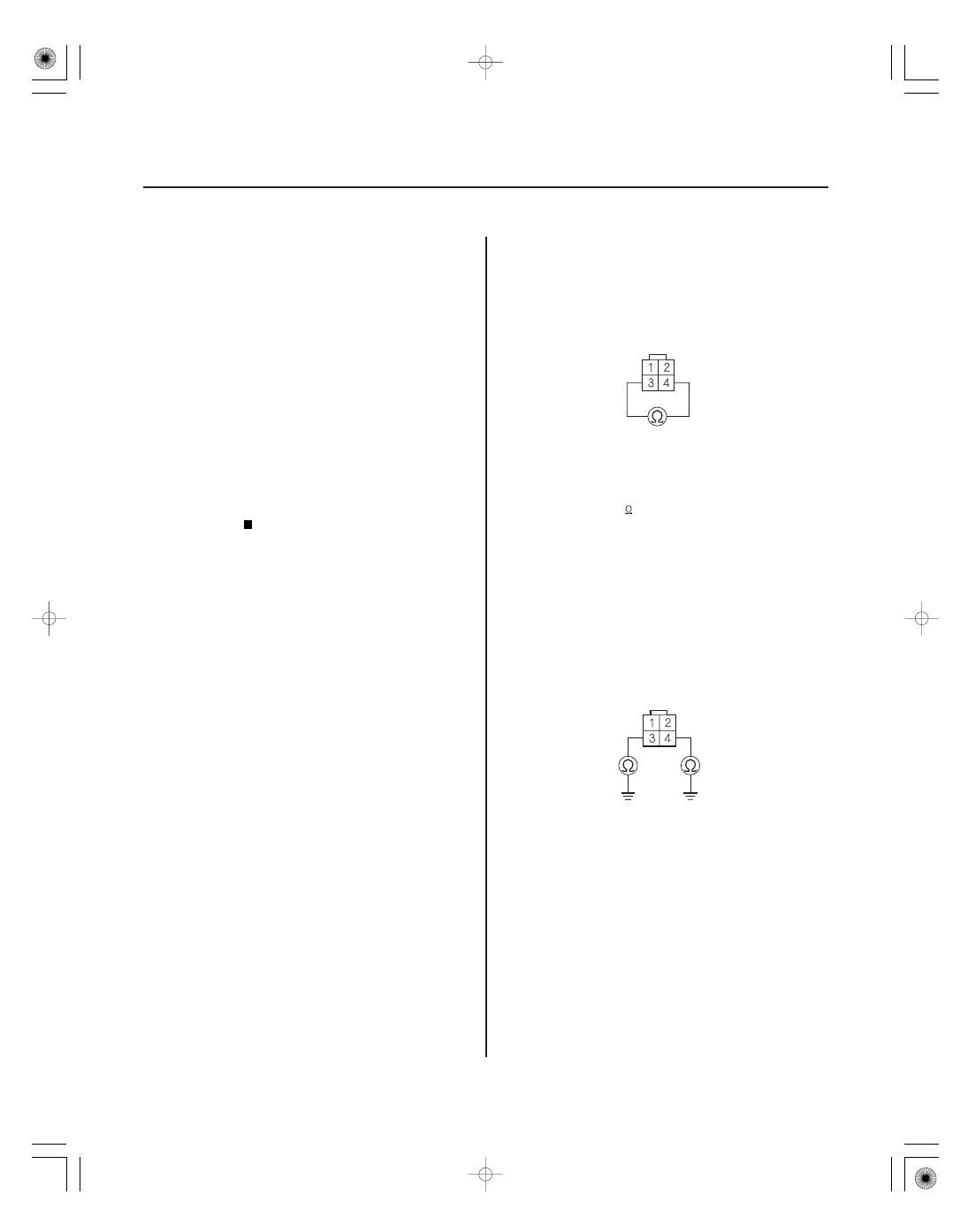
SECONDARY HO2S (SENSOR 2) 4P CONNECTOR
SECONDARY HO2S (SENSOR 2) 4P CONNECTOR
Secondary HO2S (Sensor 2)
Heater Circuit Malfunction
(2005-2006 models)
1. Turn the ignition switch ON (II).
2. Clear the DTC with the HDS.
3. Start the engine.
4. Check for Temporary DTCs or DTCs with the HDS.
Go to step 5.
Intermittent failure, system is OK at this time.
Check for poor connections or loose terminals at
the secondary HO2S (Sensor 2) and the
ECM/PCM.
5. Check the No. 4 ACG (10 A) fuse in the under-dash
fuse/relay box.
Go to step 6.
Repair short in the wire between the
secondary HO2S (Sensor 2) and the No. 4 ACG
(10 A) fuse, then go to step 24.
6. Turn the ignition switch OFF.
7. Disconnect the secondary HO2S (Sensor 2) 4P
connector.
8. At the secondary HO2S (Sensor 2) side, measure
resistance between secondary HO2S (Sensor 2) 4P
connector terminals No. 3 and No. 4.
Go to step 9.
Go to step 23.
9. At the secondary HO2S (Sensor 2) side, check for
continuity between body ground and secondary
HO2S (Sensor 2) 4P connector terminals No. 3 and
No. 4 individually.
Go to step 23.
Go to step 10.
Wire side of female terminals
Wire side of female terminals
Is DT C P0141 indicated?
Is the f use OK ?
Is ther e 5.0
6.4
at r oom temper atur e?
Is ther e continuity?
05/06/27 17:35:02 61S6M040_110_0158