Acura RL (1996-2004 year). Manual - part 632


  Index      Acura     Acura RL 1996-2004 year - service repair manual


Search            


Content   ..  630  631  632  633   ..


Acura RL (1996-2004 year). Manual - part 632


Control Unit Input Test

1. Remove the dashboard lower cover (see 

section 20

).

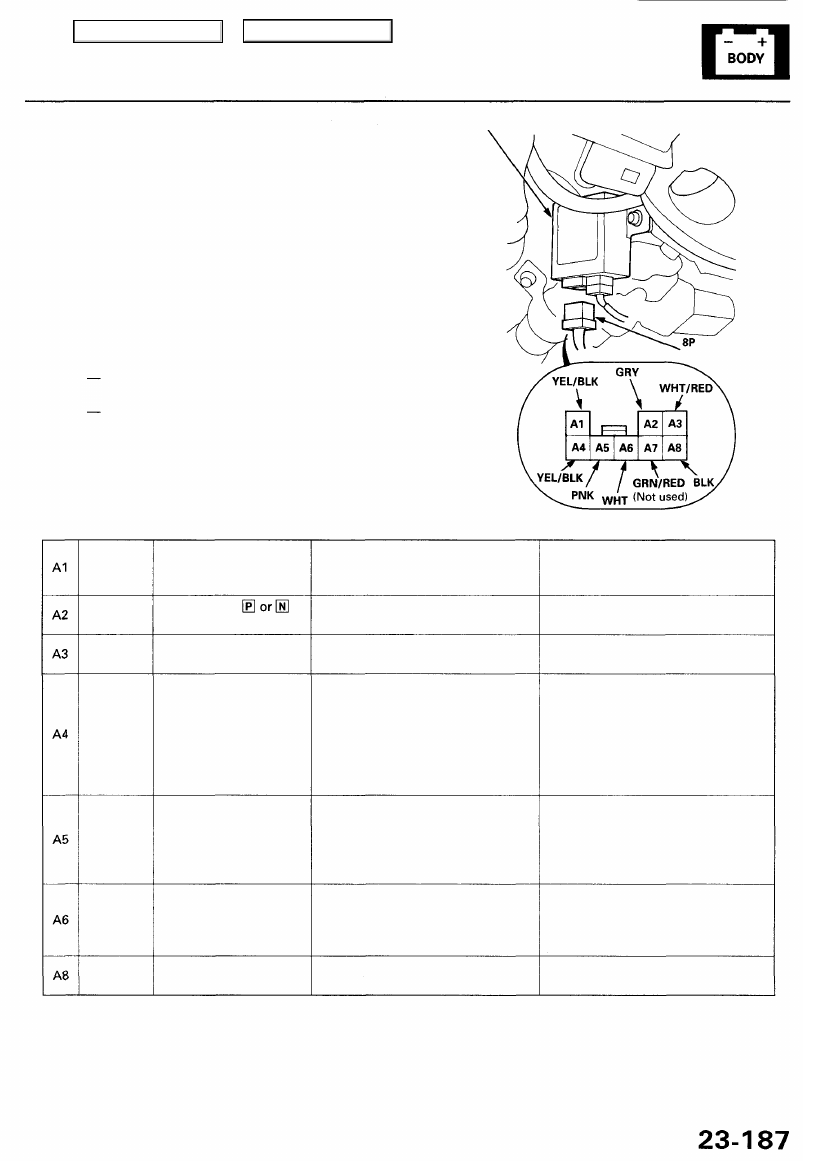
2. Disconnect the 8P connector "A" from the immobilizer

control unit.

3. Inspect the connector and socket terminals to be

sure they are all making good contact.

• If the terminals are bent, loose, or corroded, repair

them as necessary, and recheck the system.

• If the terminals look OK, make the following

input tests at the connector.

If any test indicates a problem, find and
correct the cause, then recheck the system.
If all the input tests prove OK, check the immo-
bilizer receiver and transponder.

IMMOBILIZER CONTROL UNIT

Wire side of
female terminals

Cavity Wire Test condition Test: Desired results Possible cause if result is not obtained

YEL/BLK

GRY

WHT/RED

YEL/BLK

PNK

WHT

BLK

Under all conditions

Shift lever in

Ignition switch at
START (III)

Ignition switch ON (II)

Under all conditions

Under all conditions

Under all conditions

Check for voltage to ground:

There should be battery voltage.

Check for continuity to ground:
There should be continuity.

Check for voltage to ground:
There should be battery voltage.

Check for voltage to ground:
There should be battery voltage.

Attach to ground:
The immobilizer indicator light

should come on.

*Check for continuity between the

A6 terminal and PCM 12P
connector No. 11 terminal.
There should be continuity.

Check for continuity to ground:
There should be continuity.

• Poor ground (G401, G402 or G251)
• An open in the wire

• An open in the wire

• Blown No. 56 (7.5 A) fuse in the

under-hood fuse/relay box

• Blown bulb
• Faulty gauge circuit
• An open in the wire

• Blown No. 6 (20 A) fuse in the

under-dash fuse/relay box

• Blown No. 25 (30 A) fuse in the

under-dash fuse/relay box

• Faulty PGM-FI main relay
• An open in the wire
• Poor ground (G101)

• Faulty starter cut relay
• An open in the wire

• Faulty transmission range switch
• An open in the wire

• Blown No. 6 (20 A) fuse in the

under-dash fuse/relay box.

• An open in the wire

CONNECTOR "A"

*: Use the backprobing method explained in 

section 11

.

Main Menu

Table of Contents

Immobilizer System

Immobilizer Receiver and Transponder (Key) Test

IMMOBILIZER
CONTROL
UNIT

Does the immobilizer indi-
cator blink?

Perform the control unit input
test.

YES

Try to start the engine with another

master key or valet key from this

vehicle.

Does the engine start?

Replace the transponder (igni-

tion key).

3P CONNECTOR

NO

Does the engine crank?

NO

Rewrite the immobilizer control
unit and the PCM with the PGM

Tester.

Check for an open in the WHT
wire between the immobilizer
control unit and the PCM. If the
wire is OK, rewrite the PCM with
the PGM Tester.

Does the engine start?

Immobilizer system is OK now.

Wire side of
female terminals

Is there continuity?

NO

Short in the shielded wires
between the immobilizer receiver
and the immobilizer control unit.
Replace the wire harness.

Measure resistance between the
B1 and B3 terminals of the 3P con-
nector.

Is there about 15 ohms?

YES

Faulty receiver or open in the
shielded wires between the immo-
bilizer receiver and immobilizer
control unit.

Replace the immobilizer control
unit.

1. Turn the ignition switch ON (II).

2. Check that the immobilizer

indicator light starts blinking
after two seconds.

1. Turn the ignition switch OFF.

2. Disconnect the 3P connector

"B" from the immobilizer con-

trol unit.

3. Check for continuity between

the B1 and B2, and the B3 and

B2 terminals of the 3P connec-
tor.

NO

YES

YES

NO

NO

YES

YES

Main Menu

Table of Contents

Immobilizer Receiver Replacement

1. Remove the dashboard lower cover (see

section 20

).

2. Disconnect the ignition key light socket from the

ignition key light ring by turning the socket.

IGNITION
KEY SWITCH

IGNITION KEY LIGHT
and SOCKET

9. Turn the ignition key to 0, and remove it.

IMMOBILIZER RECEIVER

10. Turn the immobilizer receiver clockwise, and

remove it.

Installation:

1. Install the new immobilizer receiver in the reverse

order of removal.

2. Insert the ignition key into the key cylinder, and turn

it to "I".

3. Insert the key cylinder into the key cylinder housing

with pushing the lock pin.

NOTE: The lock pin can be pushed by pulling the
key in position "I".

4. The remaining installation is the reverse of the

removal procedure.

NOTE: This harness is shielded and serves as a

communication link; be careful not to damage it.

7. Turn the ignition key to "I".

8. Push the lock pin, and remove the key cylinder by

pulling the ignition key.

NOTE: Don't pull on the immobilizer receiver.

3. Loosen the screw, then remove the ignition key

light ring.

4. Disconnect the immobilizer receiver 3P connector.

5. Remove the screw and the ignition key switch.

6. Remove the screw from the key cylinder housing.

IMMOBILIZER RECEIVER
3P CONNECTOR

IGNITION KEY
LIGHT RING

KEY CYLINDER
HOUSING

PUSH

LOCK PIN

KEY POSITION

KEY CYLINDER

Main Menu

Table of Contents

Driving Position Memory System (DPMS)

Component Location Index

VEHICLE SPEED SENSOR (VSS)
Troubleshooting, page 

23-86

POWER MIRRORS
Test, page 

23-359

Actuator Replacement, page 

23-360

Power Mirror Position Sensor Test,
(refer to flowchart No. 10)

DRIVING POSITION
MEMORY SWITCH
Test, page 

23-225

POWER MIRROR SWITCH
Test, page 

23-358

POWER MIRROR CONTROL UNIT
Input Test, page 

23-238

FRONT UP-DOWN
POSITION SENSOR
Test, page 

23-229

DRIVER'S POWER SEAT

REAR UP-DOWN POSITION SENSOR
Test, page 

23-229

RECLINE MOTOR
Test, page 

23-228

Replacement, 

section 20

RECLINE POSITION SENSOR
Test, page 

23-229

REAR UP-DOWN MOTOR
Test, page 

23-228

Replacement, 

section 20

POWER SEAT ADJUSTMENT SWITCH
Test, page 

23-227

Replacement, 

section 20

SLIDE MOTOR
Test, page 

23-228

Replacement, 

section 20

POWER SEAT CONTROL UNIT
Input Test, page 

23-234

SLIDE POSITION SENSOR
Test, page 

23-229

FRONT UP-DOWN MOTOR

Test, page 

23-228

Replacement, 

section 20

Main Menu

Table of Contents


Content   ..  630  631  632  633   ..