Acura RL (1996-2004 year). Manual - part 456


  Index      Acura     Acura RL 1996-2004 year - service repair manual


Search            


Content   ..  454  455  456  457   ..


Acura RL (1996-2004 year). Manual - part 456


1. Install the torque converter housing separator plate

and three dowel pins on the torque converter hous-

ing.

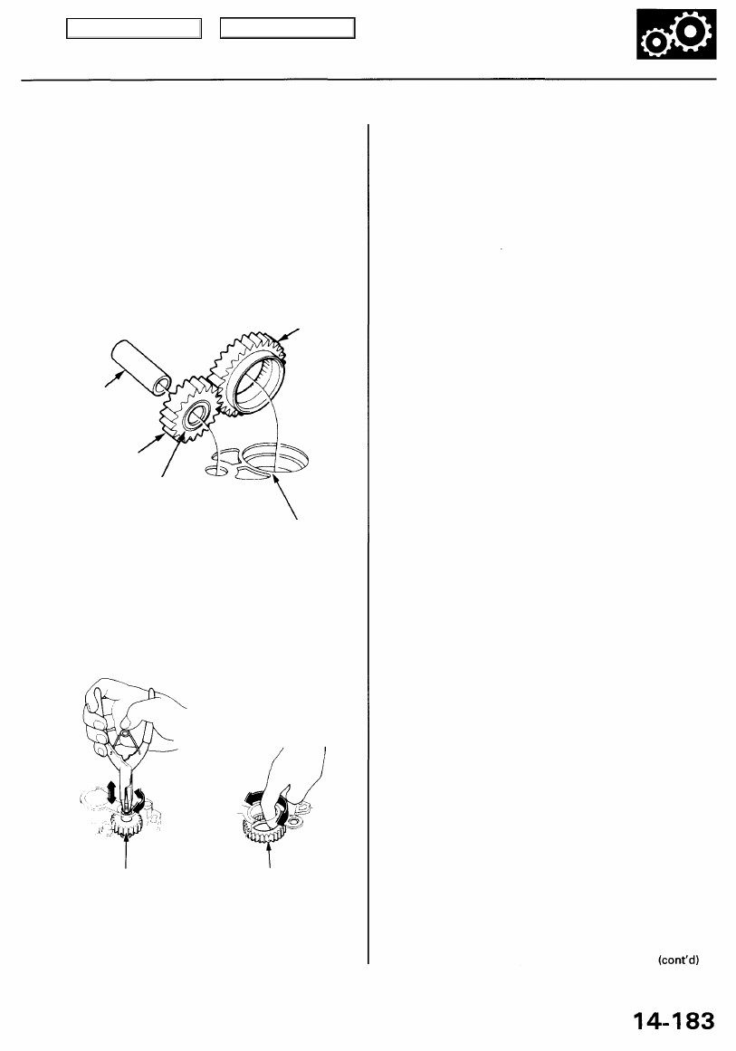
2. Install the ATF pump drive gear, ATF pump driven

gear, ATF driven gear shaft, torque converter check

valve, and spring on the torque converter housing.

NOTE: Install the ATF pump driven gear with its

grooved and chamfered side facing down.

ATF PUMP
DRIVE GEAR

ATF PUMP
DRIVEN GEAR
SHAFT

ATF PUMP
DRIVE GEAR

4. Install the accumulator body (seven bolts and eight

special bolts).

5. Install the two dowel pins on the accumulator body,

then install the accumulator cover while pressing it

down (four bolts).

6. Tighten the bolts on the ATF pump body to the

specified torque. Make sure the ATF drive gear and
the ATF driven gear shaft move smoothly.

7. If the ATF pump drive gear and ATF driven gear

shaft do not move freely, loosen the bolts on the

ATF pump body, and remove the accumulator cover
and accumulator body.

8. Realign the ATF pump driven gear shaft, reinstall

the accumulator body and the accumulator cover,
then retighten the bolts on the ATF pump body to
the specified torque. Recheck the ATF drive gear
and the ATF driven gear shaft movement.

CAUTION: Failure to align the ATF pump driven
gear shaft correctly will result in seized ATF pump
gears or a seized ATF pump driven gear shaft.

9. Install the regulator separator plate and two dowel

pins on the ATF pump body.

10. Install the Stator shaft with a new O-ring and stop

shaft.

11. Install the regulator valve body (eight 6 mm bolts

and one 8 mm bolt).

12. Install the ATF feed pipes on the accumulator body.

13. Install the park rod assembly with the detent lever

on the control shaft, and install the detent spring on

the transmission housing, if necessary (see page

14-179

).

14. Assemble the mainshaft sub-assembly (see page

14-154

).

15. Assemble the countershaft sub-assembly (see page

14-158

).

16. Install the secondary driven gear shaft in the torque

converter housing.

3. Loosely install the ATF pump body with two 8 mm

bolts and three 6 mm bolts. Make sure the ATF
pump drive gear rotates smoothly in the normal
operating direction, and the ATF pump driven gear
shaft moves smoothly in the axial and normal oper-
ating directions.

TORQUE CONVERTER HOUSING
SEPARATOR PLATE

Grooved and chamfered
side faces separator
plate.

ATF PUMP DRIVEN
GEAR SHAFT

ATF PUMP
DRIVEN GEAR

Main Menu

Table of Contents

Transmission

Reassembly (cont'd)

17. Install the mainshaft sub-assembly and the counter-

shaft sub-assembly together in the torque converter
housing.

NOTE: Do not damage the regulator valve body

when installing the shafts.

COUNTERSHAFT
SUB-ASSEMBLY

MAINSHAFT
SUB-ASSEMBLY

COUNTERSHAFT
SPEED SENSOR
WASHER

COUNTERSHAFT
SPEED SENSOR

6 x 1.0 mm
12 N-m

11.2 kgf-m,

8.7 Ibf-ft)

DOWEL PIN

DOWEL

PIN

MAINSHAFT
SPEED SENSOR
WASHER

TRANSMISSION

HOUSING

GASKET

MAINSHAFT
SPEED SENSOR

19. Place the transmission housing on the torque con-

verter housing.

CAUTION: Do not install the mainshaft and counter-
shaft speed sensors before installing the transmission
housing on the torque converter housing.

20. Install the transmission housing mounting bolts with

the transmission hanger, harness clamp bracket,
and speed sensor connector bracket, then tighten
them in two or more steps in the sequence shown.

TORQUE: 33 N-m (3.4 kgf-m, 25 Ibf-ft)

HARNESS CLAMP BRACKET

TRANSMISSION
HANGER

SPEED SENSOR
CONNECTOR
BRACKET

21. Install the mainshaft and countershaft speed sen-

sors with the washers on the transmission housing.

22. Install the countershaft 2nd gear assembly, 2nd gear

one-way clutch, needle bearings, thrust washer, and

thrust needle bearing on the countershaft.

THRUST NEEDLE

BEARING

THRUST WASHER,

45.5 x 60 mm

NEEDLE BEARINGS

NEEDLE BEARING

COUNTERSHAFT

THRUST NEEDLE
BEARING

2ND GEAR

COLLAR

MAINSHAFT

23. Install the 2nd gear collar, thrust needle bearing,

and needle bearing on the mainshaft.

TRANSMISSION
HOUSING

TRANSMISSION HOUSING

BOLTS

8 x 1.25 mm

33 N-m (3.4 kgf-m, 25 Ibf-ft)

18. Install the two dowel pins and a new gasket on the

torque converter housing.

2ND GEAR ONE-WAY
CLUTCH

2ND GEAR
ASSEMBLY

Main Menu

Table of Contents

4. Combine the mainshaft 2nd gear with the park gear,

then install them on their respective shafts.

MAINSHAFT

MAINSHAFT
2ND GEAR

COUNTERSHAFT

PARK GEAR

25. Using the special tool as shown, tap the park gear

very lightly to install it in the 2nd gear one-way
clutch.

DRIVER I.D.

40 mm

07746-0030100

MAINSHAFT

PARK GEAR

26. Install the park pawl shaft, spring, pawl, and sleeve

in the transmission housing (see page 

14-179

).

27. Install the ATF feed pipe in the accumulator cover.

ATF FEED PIPE

ACCUMULATOR
COVER

28. Install the reverse clutch distance collar and a new

countershaft conical spring washer on the counter-
shaft.

NOTE: Install the conical spring washers in the

direction shown.

24 mm WASHER

BALL BEARING

25 mm THRUST
WASHER

THRUST NEEDLE
BEARING
REVERSE GEAR

THRUST NEEDLE
BEARING

NEEDLE BEARING
REVERSE GEAR

COLLAR

O-RINGS
Replace.

REVERSE CLUTCH
ASSEMBLY

24 mm WASHER

BALL BEARING

REVERSE GEAR

REVERSE GEAR
DISTANCE

COLLAR

CONICAL SPRING
WASHER
2ND CLUTCH
ASSEMBLY

O-RINGS
Replace.

29 mm THRUST
WASHER

MAINSHAFT THRUST NEEDLE

BEARING

CONICAL SPRING
WASHER

REVERSE CLUTCH
DISTANCE COLLAR

COUNTERSHAFT

29. Install the thrust needle bearing and 29 mm thrust

washer on the mainshaft.

30. Install new O-rings on the countershaft and main-

shaft.

NOTE: Before installing the O-rings, wrap the shaft

splines with tape to prevent damage to the O-rings.

31. Install the 2nd clutch assembly on the mainshaft,

then install the reverse clutch assembly, reverse
gear collar, needle bearing, thrust needle bearing,

reverse gear, thrust needle bearing, 25 mm thrust

washer and ball bearing on the countershaft.

32. Install a new mainshaft conical spring washer,

reverse gear distance collar, reverse gear and ball
bearing on the mainshaft.

Main Menu

Table of Contents

Transmission

Reassembly (cont'd)

33. Install the special tool onto the mainshaft as shown.

MAINSHAFT HOLDER

07924-PJ4010A

34. Engage the park pawl with the park gear by moving

the detent lever to the position.

35. Coat the 24 mm washers with ATF, then install

them and the new locknuts on each shaft.

36. Tighten the locknuts to the specified torque using a

torque wrench.

TORQUE: 127 N-m (13.0 kgf-m, 94 Ibf-ft)

NOTE: Countershaft locknut has left-hand threads.

37. Stake each locknut into its shaft using a 3.5 mm

(0.14 in) punch as shown.

0.7- 1.2 mm

(0.03 - 0.05 in)

3.5 mm (0.14 in)

COUNTERSHAFT
LOCKNUT

MAINSHAFT
LOCKNUT

38. Install two dowel pins, four ATF feed pipes with new

O-rings, and a new rear cover gasket on the trans-
mission housing.

39. Install the rear cover, and engage the reverse gears

while rotating the mainshaft.

REVERSE
IDLER GEAR

MAINSHAFT
REVERSE

GEAR

COUNTERSHAFT
REVERSE
GEAR

40. Push on the rear cover while expanding the snap

ring with the snap ring pliers until the ring snaps in
place around the bearing.
NOTE: Make sure the snap ring fits in place around

the bearing. If not, raise the countershaft to fit the
snap ring in place.

SNAP RING

BALL BEARING

41. Install the transmission range switch harness bracket

and the bolts, then tighten the bolts on the rear cover
(ten bolts).

TORQUE: 26 N-m (2.7 kgf-m, 20 Ibf-ft)

42. Apply liquid gasket (P/N 08718-0001) to the sealing

bolt threads, and install the sealing bolt and the

34 mm washer ('96 (M5DA - 1026239 ~) - 01 mod-
els) on the rear cover.
TORQUE:
• '96 model (~ M5DA - 1026238)

78 N-m (8.0 kgf-m, 58 Ibf-ft)

• '96 (M5DA - 1026239~) - 01 models

98 N-m (10.0 kgf-m, 72 Ibf-ft)

REAR COVER

Main Menu

Table of Contents


Content   ..  454  455  456  457   ..