Acura RL. Manual - part 458


  Index      Acura     Acura RL - service repair manual 2005-2008 year


Search            


Content   ..  456  457  458  459   ..


Acura RL. Manual - part 458


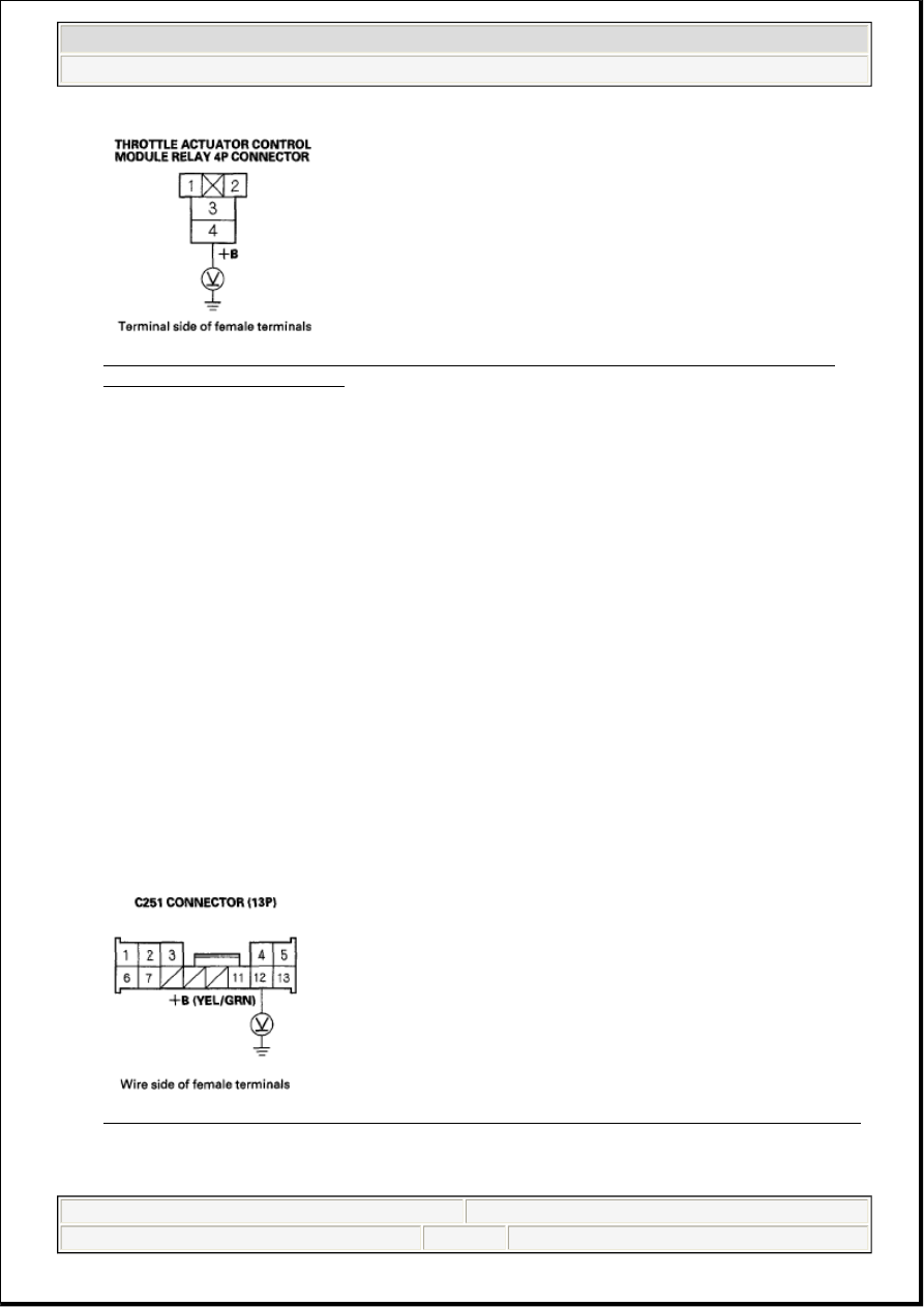
Fig. 64: Measuring Voltage Between Throttle Actuator Control Module Relay 4P Connector 
Terminal 4 And Body Ground
 
Courtesy of AMERICAN HONDA MOTOR CO., INC. 

Is there battery voltage?  

YES - Go to step 19. 

NO - Go to step 18. 

18. Check the No. 1 THROTTLE ACTUATOR CONTROL (15A) fuse in the driver's under-dash 

fuse/relay box. 

Is the fuse OK?  

YES - Repair open in the wire between the throttle actuator control module relay (+B line) and the 
No. 1 THROTTLE ACTUATOR CONTROL (15A) fuse, then go to step 63. 

NO - Repair short in the wire between the throttle actuator control module relay (+B line) and the No. 
1 THROTTLE ACTUATOR CONTROL (15A) fuse, then go to step 63. 

19. Install the throttle actuator control module relay.  

20. Turn the ignition switch ON (II).  

21. Measure voltage between C251 connector (13P) terminal No. 12 and body ground. 

Fig. 65: Measuring Voltage Between C251 Connector (13P) Terminal No. 12 And Body Ground
Courtesy of AMERICAN HONDA MOTOR CO., INC.
 

Is there battery voltage for about 2 seconds?


2007 Acura RL 

2005-08 ENGINE PERFORMANCE Electronic Throttle Control System - RL


me 


Friday, June 05, 2009 2:29:49 PM

Page 53 

© 2005 Mitchell Repair Information Company, LLC. 

YES - Go to step 52. 

NO - Go to step 22. 

22. Turn the ignition switch OFF.  

23. Remove the throttle actuator control module relay (A). 

Fig. 66: Identifying Throttle Actuator Control Module Relay 
Courtesy of AMERICAN HONDA MOTOR CO., INC. 

24. Check the throttle actuator control module relay (see POWER RELAY TEST ). 

Is the throttle actuator control module relay OK?  

YES - Go to step 25. 

NO - Replace the throttle actuator control module relay, then go to step 63. 

25. Turn the ignition switch ON (II).  

26. Measure voltage between throttle actuator control module relay 4P connector terminal No. 2 and body 

ground. 

Fig. 67: Measuring Voltage Between Throttle Actuator Control Module Relay 4P Connector 
Terminal 2 And Body Ground


2007 Acura RL 

2005-08 ENGINE PERFORMANCE Electronic Throttle Control System - RL


me 


Friday, June 05, 2009 2:29:49 PM

Page 54 

© 2005 Mitchell Repair Information Company, LLC. 

Courtesy of AMERICAN HONDA MOTOR CO., INC.

Is there battery voltage?  

YES - Go to step 27. 

NO - Repair open in the wire between the throttle actuator control module relay and PGM-FI main 
relay 1 (Fl MAIN), then go to step 62. 

27. Turn the ignition switch OFF.  

28. Jump the SCS line with the HDS.  

29. Disconnect PCM connector E (31P).  

30. Check for continuity between PCM connector terminal E3 and throttle actuator control module relay 

4P connector terminal No. 1. 

Fig. 68: Checking Continuity Between PCM Connector Terminal E3 And Throttle Actuator 
Control Module Relay 4P Terminal 1
 
Courtesy of AMERICAN HONDA MOTOR CO., INC. 

Is there continuity?  

YES - Go to step 31. 

NO - Repair open in the wire between the PCM (E3) and the throttle actuator control module relay, 
then go to step 63. 

31. Check for continuity between C251 connector (13P) terminal No. 12 and body ground. 


2007 Acura RL 

2005-08 ENGINE PERFORMANCE Electronic Throttle Control System - RL


me 


Friday, June 05, 2009 2:29:49 PM

Page 55 

© 2005 Mitchell Repair Information Company, LLC. 

Fig. 69: Checking Continuity Between C251 Connector (13P) Terminal No. 12 And Body 
Ground
 
Courtesy of AMERICAN HONDA MOTOR CO., INC. 

Is there continuity?  

YES - Repair short in the wire between the throttle actuator control module and the throttle actuator 
control module relay (+B line), then go to step 63. 

NO - Go to step 32. 

32. Check for continuity between throttle actuator control module relay 4P connector terminal No. 3 and 

C251 connector (13P) terminal No. 12. 

Fig. 70: Checking Continuity Between Throttle Actuator Control Module Relay 4P Connector 
Terminal 3 And C251 (13P) Terminal 12
 
Courtesy of AMERICAN HONDA MOTOR CO., INC. 

Is there continuity?  

YES - Go to step 33. 

NO - Repair open in the wire between the throttle actuator control module relay and the C251 
connector (+B line), then go to step 63. 

33. Disconnect the throttle actuator control module 16P connector (see THROTTLE ACTUATOR 

CONTROL MODULE REPLACEMENT ).  

34. Check for continuity between C251 connector (13P) terminal No. 12 and body ground. 


2007 Acura RL 

2005-08 ENGINE PERFORMANCE Electronic Throttle Control System - RL


me 


Friday, June 05, 2009 2:29:49 PM

Page 56 

© 2005 Mitchell Repair Information Company, LLC. 


Content   ..  456  457  458  459   ..