Acura RL. Manual - part 446


  Index      Acura     Acura RL - service repair manual 2005-2008 year


Search            


Content   ..  444  445  446  447   ..


Acura RL. Manual - part 446


14. Disconnect the C251 connector (13P) between the PCM subharness and the throttle actuator control 

module subharness.  

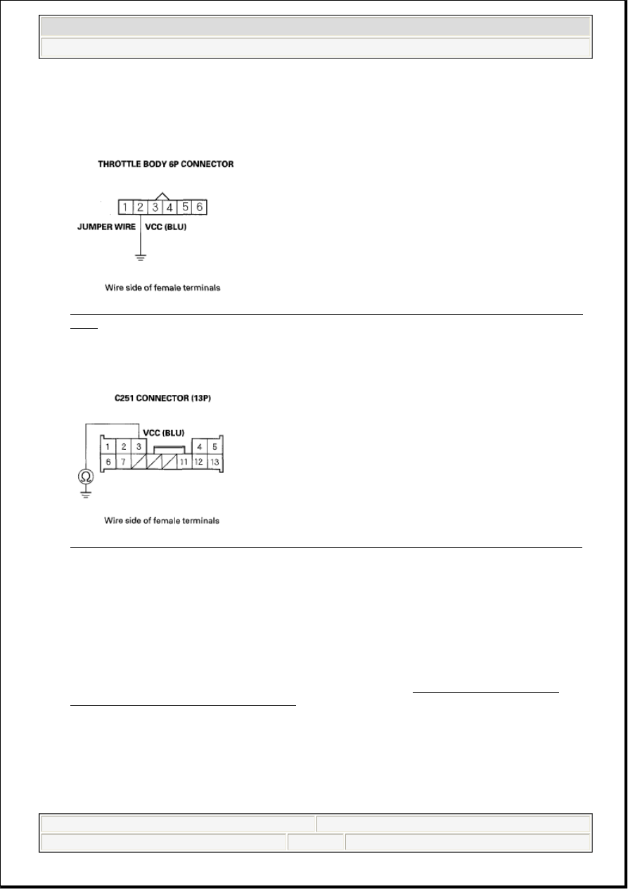
15. Connect throttle body 6P connector terminal No. 2 to body ground with a jumper wire. 

Fig. 6: Connecting Throttle Body 6P Connector Terminal No. 2 To Body Ground With Jumper 
Wire
 
Courtesy of AMERICAN HONDA MOTOR CO., INC. 

16. Check for continuity between C251 connector (13P) terminal No. 3 and body ground. 

Fig. 7: Checking Continuity Between C251 Connector (13P) Terminal No. 3 And Body Ground
Courtesy of AMERICAN HONDA MOTOR CO., INC.
 

Is there continuity?  

YES - Go to step 21. 

NO - Repair open in the wire between the throttle body and the throttle actuator control module (VCC 
line), then go to step 21. 

17. Disconnect the throttle actuator control module 16P connector (see THROTTLE ACTUATOR 

CONTROL MODULE REPLACEMENT ).  

18. Check for continuity between throttle actuator control module 16P connector terminal No. 11 and 

C251 connector (13P) terminal No. 3. 


2007 Acura RL 

2005-08 ENGINE PERFORMANCE Electronic Throttle Control System - RL


me 


Friday, June 05, 2009 2:29:49 PM

Page 5 

© 2005 Mitchell Repair Information Company, LLC. 

Fig. 8: Checking Continuity Between Throttle Actuator Control Module 16P Connector 
Terminal 11 And C251 (13P) Terminal 3
 
Courtesy of AMERICAN HONDA MOTOR CO., INC. 

Is there continuity?  

YES - Go to step 26. 

NO - Repair open in the wire between the throttle actuator control module (VCC line) and the C251 
connector, then go to step 21. 

19. Turn the ignition switch OFF.  

20. Replace the throttle body (see THROTTLE BODY REMOVAL/INSTALLATION ).  

21. Reconnect all connectors.  

22. Turn the ignition switch ON (II).  

23. Reset the PCM with the HDS.  

24. Do the PCM idle learn procedure (see PCM IDLE LEARN PROCEDURE ).  

25. Check for Temporary DTCs or DTCs with the HDS. 

Is DTC P0122 indicated?  

YES - Check for poor connections or loose terminals at the throttle body and the throttle actuator 
control module, then go to step 1. 

NO - Troubleshooting is complete. If any other Temporary DTCs or DTCs are indicated, go to the 
indicated DTCs troubleshooting. 

26. Reconnect all connectors.  

27. Update the PCM if it does not have the latest software (see UPDATING THE PCM ), or substitute a 

known-good PCM (see THROTTLE BODY CLEANING ).  

28. Check for Temporary DTCs or DTCs with the HDS. 

Is DTC P0122 indicated?  

YES - Check for poor connections or loose terminals at the throttle body and the throttle actuator 
control module. If the PCM was updated, substitute a known-good PCM (see SUBSTITUTING THE 
PCM
 ), then recheck. If the PCM was substituted, go to step 1.


2007 Acura RL 

2005-08 ENGINE PERFORMANCE Electronic Throttle Control System - RL


me 


Friday, June 05, 2009 2:29:49 PM

Page 6 

© 2005 Mitchell Repair Information Company, LLC. 

NO - If the PCM was updated, troubleshooting is complete. If the PCM was substituted, replace the 
original PCM (see PCM REPLACEMENT ). If any other Temporary DTCs or DTCs are indicated, 
go to the indicated DTCs troubleshooting. 

DTC P0123: TP SENSOR A CIRCUIT HIGH VOLTAGE 

1. Turn the ignition switch ON (II).  

2. Clear the DTC with the HDS.  

3. Check TP SENSOR A in the DATA LIST with the HDS. 

Is there about 4.8 V or more?  

YES - Go to step 4. 

NO - Intermittent failure, the system is OK at this time. Check for poor connections or loose terminals 
at the throttle body and the throttle actuator control module. 

4. Check for Temporary DTCs or DTCs with the HDS. 

Are DTC P0123 and P0223 indicated at the same time?  

YES - Go to step 12. 

NO - Go to step 5. 

5. Measure voltage between throttle body 6P connector terminal No. 1 and body ground. 

Fig. 9: Measuring Voltage Between Throttle Body 6P Connector Terminal No. 1 And Body 
Ground
 
Courtesy of AMERICAN HONDA MOTOR CO., INC. 

Is there about 5 V?  

YES - Go to step 19. 

NOTE:

Before you troubleshoot, record all freeze data and any on-board snapshot, 
and review the general troubleshooting information (see GENERAL 
TROUBLESHOOTING INFORMATION ).


2007 Acura RL 

2005-08 ENGINE PERFORMANCE Electronic Throttle Control System - RL


me 


Friday, June 05, 2009 2:29:49 PM

Page 7 

© 2005 Mitchell Repair Information Company, LLC. 

NO - Go to step 6. 

6. Turn the ignition switch OFF.  

7. Disconnect the throttle body 6P connector.  

8. Disconnect the C251 connector (13P) between the PCM subharness and the throttle actuator control 

module subharness.  

9. Connect throttle body 6P connector terminal No. 1 to body ground with a jumper wire. 

Fig. 10: Connecting Throttle Body 6P Connector Terminal No. 1 To Body Ground With Jumper 
Wire
 
Courtesy of AMERICAN HONDA MOTOR CO., INC. 

10. Check for continuity between C251 connector (13P) terminal No. 4 and body ground. 

Fig. 11: Checking Continuity Between C251 Connector (13P) Terminal No. 4 And Body Ground
Courtesy of AMERICAN HONDA MOTOR CO., INC.
 

Is there continuity?  

YES - Go to step 11. 

NO - Repair open in the wire between the throttle body and the C251 connector (TPSA line), then go 
to step 21. 

10. Disconnect the throttle actuator control module 16P connector (see THROTTLE ACTUATOR 

CONTROL MODULE REPLACEMENT ).  

11. Check for continuity between throttle actuator control module 16P connector terminal No. 10 and 

C251 connector (13P) terminal No. 4. 


2007 Acura RL 

2005-08 ENGINE PERFORMANCE Electronic Throttle Control System - RL


me 


Friday, June 05, 2009 2:29:49 PM

Page 8 

© 2005 Mitchell Repair Information Company, LLC. 


Content   ..  444  445  446  447   ..