Acura RL. Manual - part 310
 

  Index      Acura     Acura RL - service repair manual 2005-2008 year


Search            


Content   ..  308  309  310  311   ..


Acura RL. Manual - part 310


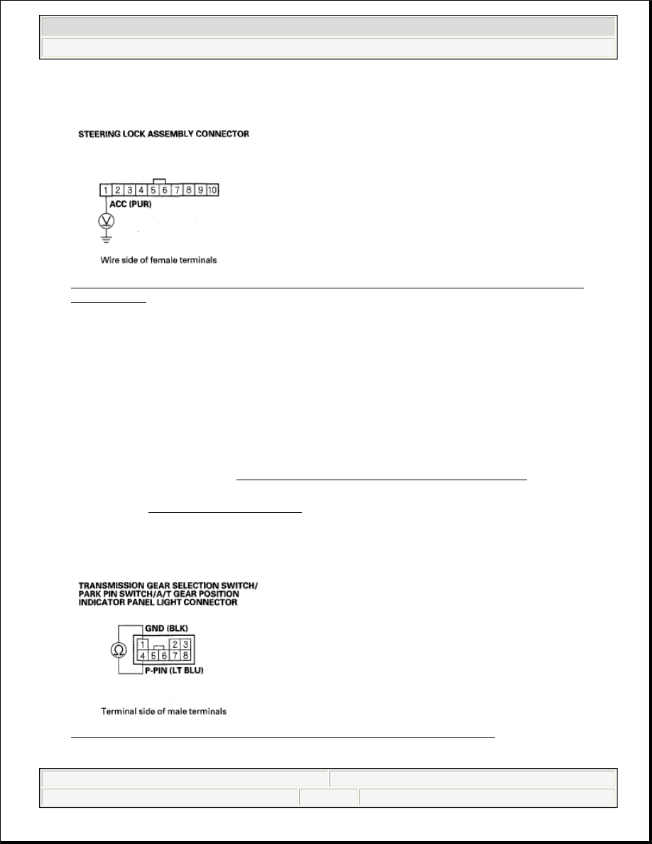
5. Measure the voltage between the steering lock assembly connector terminal No. 1 and body ground. 

Fig. 424: Measuring Voltage Between Steering Lock Assembly Connector Terminal No. 1 And 
Body Ground
 
Courtesy of AMERICAN HONDA MOTOR CO., INC. 

Is there battery voltage?  

YES - Go to step 6. 

NO - Check for a blown No. 32 (10 A) fuse in the driver's under-dash fuse/relay box. If the fuse is OK, 
repair open in the wire between the driver's under-dash fuse/relay box and the steering lock assembly 
connector. 

6. Turn the ignition switch to ACCESSORY (I), and shift to P.  

7. Remove the center console (see CENTER CONSOLE REMOVAL/INSTALLATION ).  

8. Disconnect the transmission gear selection switch/park pin switch/A/T gear position indicator panel light 

connector (see PARK PIN SWITCH TEST ).  

9. Check for continuity between the transmission gear selection switch/park pin switch/A/T gear position 

indicator panel light connector terminals No. 1 and No. 4 while the shift lever is in P, and when the shift 
lever is out of P. 

Fig. 425: Checking Continuity Between Connector Terminals No. 1 And No. 4 
Courtesy of AMERICAN HONDA MOTOR CO., INC.


2007 Acura RL 

2005-08 TRANSMISSION Automatic Transmission - RL


me 


Friday, June 05, 2009 1:18:16 PM

Page 411 

© 2005 Mitchell Repair Information Company, LLC. 

Is there continuity when the shift lever is in any position other than P, and no continuity when the shift 
lever is in P?
  

YES - Check for an open in the wire between the multiplex integrated control unit, PCM connector 
terminal D14, and the transmission gear selection switch/park pin switch/A/T gear position indicator 
panel light connector. If the wire is OK, substitute a known-good multiplex integrated control unit or 
PCM, then recheck. 

NO - Replace the park pin switch (see PARK PIN SWITCH TEST ). 

KEY INTERLOCK SOLENOID TEST 

SRS components are located in this area. Review the SRS component locations (see COMPONENT 
LOCATION INDEX
 ) and the precautions and procedures (see PRECAUTIONS AND PROCEDURES ) in 
the SRS before doing repairs or service. 

1. Remove the driver's dashboard lower cover and the lower steering column cover.  

2. Disconnect the steering lock assembly connector.  

3. Remove the built-in key from the remote. Insert the key in the key cylinder, then turn the ignition key to 

ACCESSORY (I).  

4. Connect the positive battery terminal to the steering lock assembly connector terminal No. 1, and connect 

the negative battery terminal to No. 10 terminal. Make sure that the ignition key cannot be turned to 
LOCK (0). Release the battery terminals, and make sure that the key can be turned to LOCK (0) and 
removed from the cylinder. 

Fig. 426: Identifying Steering Lock Assembly Connector Terminal No. 1 And No. 10 
Courtesy of AMERICAN HONDA MOTOR CO., INC. 

5. If the key interlock solenoid works improperly, replace the ignition key cylinder/steering lock assembly 

(see STEERING LOCK REPLACEMENT ).  

SHIFT LOCK SOLENOID TEST 

1. Connect the HDS to the DLC (A). 


2007 Acura RL 

2005-08 TRANSMISSION Automatic Transmission - RL


me 


Friday, June 05, 2009 1:18:16 PM

Page 412 

© 2005 Mitchell Repair Information Company, LLC. 

Fig. 427: Identifying Data Link Connector 
Courtesy of AMERICAN HONDA MOTOR CO., INC. 

2. Select SHIFT LOCK SOLENOID TEST in the MISCELLANEOUS TEST MENU, and check that the 

shift lock solenoid operates with the HDS.  

3. Check that the shift lever can be moved out of P with Shift Lock Solenoid: ON. Move the shift lever back 

in P, and make sure it locks with Shift Lock Solenoid: OFF.  

4. Check that the shift lock releases when the shift lock release is pushed, and check that it locks when the 

shift lock release is released.  

5. If the shift lock solenoid does not work properly, do the shift lock system troubleshooting (see SHIFT 

LOCK SYSTEM/REVERSE LOCK SYSTEM CIRCUIT TROUBLESHOOTING ).  

SHIFT LOCK SOLENOID REPLACEMENT 

1. Remove the center console (see CENTER CONSOLE REMOVAL/INSTALLATION ).  

2. Release the tab (A) retaining the shift lock solenoid. 

Fig. 428: Removing Tab Retaining The Shift Lock Solenoid


2007 Acura RL 

2005-08 TRANSMISSION Automatic Transmission - RL


me 


Friday, June 05, 2009 1:18:16 PM

Page 413 

© 2005 Mitchell Repair Information Company, LLC. 

Courtesy of AMERICAN HONDA MOTOR CO., INC.

3. Raise the shift lock solenoid bushing (B) just enough to slide the shift lock solenoid out.  

4. Install the shift lock solenoid plunger (C) and plunger spring (D) in the new shift lock solenoid (E).  

5. Apply silicone grease to joint of the shift lock solenoid plunger, if necessary.  

6. Install the new shift lock solenoid by aligning the joint of the shift lock solenoid plunger with the tip of 

the shift lock stop (F).  

7. Install the center console (see CENTER CONSOLE REMOVAL/INSTALLATION ).  

PARK PIN SWITCH TEST 

1. Remove the center console (see CENTER CONSOLE REMOVAL/INSTALLATION ).  

2. Disconnect the transmission gear selection switch/park pin switch/A/T gear position indicator panel light 

connector. 

Fig. 429: Identifying A/T Gear Position Indicator Panel Light Connector 
Courtesy of AMERICAN HONDA MOTOR CO., INC. 

3. Shift the shift lever into P, then check for continuity between the connector terminals No. 1 and No. 4. 

There should be no continuity.  

4. Shift out of P, and check for continuity between the terminals No. 1 and No. 4. There should be 

continuity.  

5. If the park pin switch fails the test, replace it (see PARK PIN SWITCH TEST ).  

6. Install the center console (see CENTER CONSOLE REMOVAL/INSTALLATION ).  

PARK PIN SWITCH REPLACEMENT 

1. Remove the center console (see CENTER CONSOLE REMOVAL/INSTALLATION ). 


2007 Acura RL 

2005-08 TRANSMISSION Automatic Transmission - RL


me 


Friday, June 05, 2009 1:18:16 PM

Page 414 

© 2005 Mitchell Repair Information Company, LLC. 


Content   ..  308  309  310  311   ..