Acura RL. Manual - part 241


  Index      Acura     Acura RL - service repair manual 2005-2008 year


Search            


Content   ..  239  240  241  242   ..


Acura RL. Manual - part 241


1. Clear the DTC with the HDS.  

2. Check for proper output shaft (countershaft) speed sensor installation (see INPUT SHAFT 

(MAINSHAFT) SPEED SENSOR REPLACEMENT ). If the sensor is installed improperly, correct 
the problem, then go to step 38.  

3. Raise the vehicle on a lift, make sure it is securely supported, and allow the all four wheels to rotate 

freely.  

4. Start the engine, and turn the VSA off (the light on the VSA OFF switch comes on). Run the vehicle in 

either 2nd, 3rd, 4th, or 5th gear (not 1st) in M (sequential sportshift mode) with the engine speed at 2,000 
rpm or higher for at least 10 seconds. Slow down and stop the wheels.  

5. Monitor the OBD STATUS for P0721 or P0722 in the DTCs/Freeze Data in A/T Mode Menu for a 

pass/fail. 

Does the HDS indicate FAILED?  

YES - Go to step 6. 

NO - Intermittent failure, the system is OK at this time. Check for loose or poor connections at the PCM 
and the output shaft (countershaft) speed sensor connectors. If the HDS indicates NOT COMPLETED, 
return to step 4 and recheck. 

6. Turn the ignition switch to LOCK (0).  

7. Jump the SCS line with the HDS.  

8. Disconnect PCM connectors A (31P) and B (24P).  

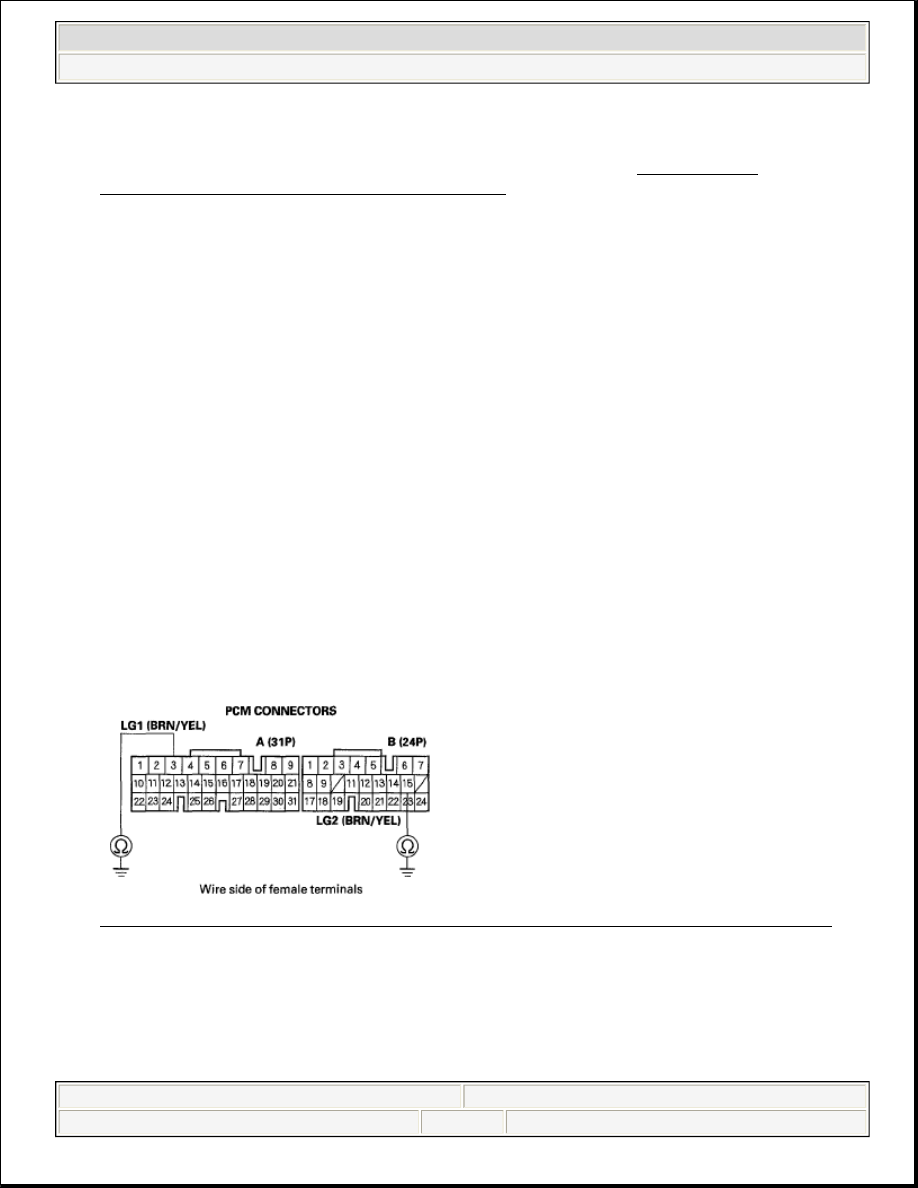
9. Check for continuity between PCM connector terminals A3 and body ground, and between B15 and body 

ground. 

Fig. 107: Checking Continuity Between PCM Connector Terminals A3[B15] And Body Ground 
Courtesy of AMERICAN HONDA MOTOR CO., INC. 

Is there continuity?  

YES - Go to step 10. 

NO - Repair open in the wires between PCM connector terminals A3, B15, and ground (G101, G102), or 


2007 Acura RL 

2005-08 TRANSMISSION Automatic Transmission - RL


me 


Friday, June 05, 2009 1:18:12 PM

Page 135 

© 2005 Mitchell Repair Information Company, LLC. 

repair poor ground (G101, G102), then go to step 37.

10. Connect PCM connectors A (31P) and B (24P).  

11. Disconnect the output shaft (countershaft) speed sensor connector.  

12. Turn the ignition switch to ON (II).  

13. Measure the voltage between output shaft (countershaft) speed sensor connector terminal No. 1 and body 

ground. 

Fig. 108: Measuring Voltage Between Output Shaft (Countershaft) Speed Sensor Connector 
Terminal No. 1 And Body Ground
 
Courtesy of AMERICAN HONDA MOTOR CO., INC. 

Is there about 5 V?  

YES - Go to step 14. 

NO - Go to step 27. 

14. Turn the ignition switch to LOCK (0).  

15. Disconnect PCM connector B (24P).  

16. Check for continuity between output shaft (countershaft) speed sensor connector terminal No. 2 and body 

ground. 

Fig. 109: Checking Continuity Between Output Shaft (Countershaft) Speed Sensor Connector 


2007 Acura RL 

2005-08 TRANSMISSION Automatic Transmission - RL


me 


Friday, June 05, 2009 1:18:12 PM

Page 136 

© 2005 Mitchell Repair Information Company, LLC. 

Terminal No. 2 And Body Ground 
Courtesy of AMERICAN HONDA MOTOR CO., INC. 

Is there continuity?  

YES - Repair short in the wire between PCM connector terminal B19 and the output shaft (countershaft) 
speed sensor connector, then go to step 37. 

NO - Go to step 17. 

17. Disconnect PCM connector C (22P).  

18. Check for continuity between PCM connector terminal C4 and output shaft (countershaft) speed sensor 

connector terminal No. 3. 

Fig. 110: Checking Continuity Between PCM Terminal C4 And Output Shaft (Countershaft) Speed 
Sensor Terminal No. 3
 
Courtesy of AMERICAN HONDA MOTOR CO., INC. 

Is there continuity?  

YES - Go to step 19. 

NO - Repair open in the wire between the output shaft (countershaft) speed sensor connector and PCM 
connector terminal C4, then go to step 37. 

19. Connect PCM connectors B (24P) and C (22P).  

20. Turn the ignition switch to ON (II).  

21. Measure the voltage between output shaft (countershaft) speed sensor connector terminals No. 2 and No. 

3. 


2007 Acura RL 

2005-08 TRANSMISSION Automatic Transmission - RL


me 


Friday, June 05, 2009 1:18:12 PM

Page 137 

© 2005 Mitchell Repair Information Company, LLC. 

Fig. 111: Measuring Voltage Between Output Shaft (Countershaft) Speed Sensor Connector 
Terminals No. 2 And 3
 
Courtesy of AMERICAN HONDA MOTOR CO., INC. 

Is there about 5 V?  

YES - Go to step 22. 

NO - Go to step 26. 

22. Connect the output shaft (countershaft) speed sensor connector.  

23. Measure the voltage between PCM connector terminals B19 and A3 or B15. 

Fig. 112: Measuring Voltage Between PCM Connector Terminals B19 And A3 Or B15 
Courtesy of AMERICAN HONDA MOTOR CO., INC. 

Is there voltage 0 V or about 5 V?  

YES - Go to step 24. 

NO - Replace the output shaft (countershaft) speed sensor (see INPUT SHAFT (MAINSHAFT) 
SPEED SENSOR REPLACEMENT
 ), then go to step 37. 

24. Start the engine, and run the vehicle in D (on the lift).  

25. While holding the engine at an engine speed 2,000 rpm or higher, measure the voltage between PCM 


2007 Acura RL 

2005-08 TRANSMISSION Automatic Transmission - RL


me 


Friday, June 05, 2009 1:18:12 PM

Page 138 

© 2005 Mitchell Repair Information Company, LLC. 


Content   ..  239  240  241  242   ..