Acura RL. Manual - part 228
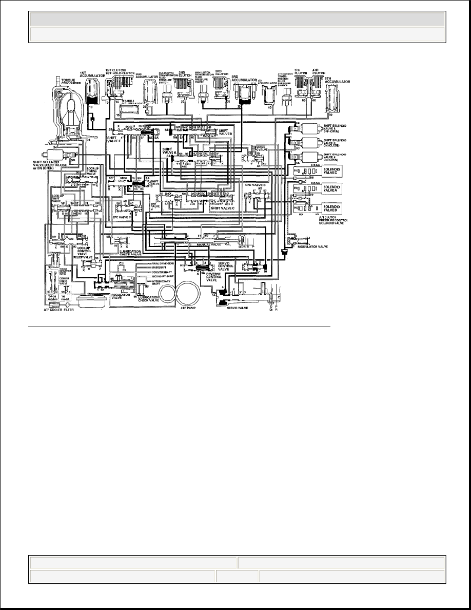
Fig. 50: Hydraulic Pressure Flow Diagram (D Position: Driving In 3rd Gear)
Courtesy of AMERICAN HONDA MOTOR CO., INC.
D Position: Shifting between 3rd gear and 4th gear
As the speed of the vehicle reaches the programmed value, the PCM turns shift solenoid valve C OFF, and shift
solenoid valve C uncovers the port of shift solenoid valve C pressure (SC) to shift valve C. Shift solenoid valve
A remains ON, and shift solenoid valve B remains OFF. Shift valve C is moved to the right side to switch the
port of line pressure (4) and CPC B pressure (4B) leading to the 3rd clutch. Shift valve C also uncovers the port
of CPC A pressure (4A) leading to the 4th clutch. The PCM actuates A/T clutch pressure control solenoid
valves A and B. A/T clutch pressure control solenoid valve A pressure (56) is applied to CPC valve A, and A/T
clutch pressure control solenoid valve B pressure (57) is applied to CPC valve B. CPC valve A regulates line
pressure (4), and line pressure (4) becomes CPC A pressure (4A). CPC A pressure (4A) flows to shift valve B
via shift valves C and A, and becomes 4th clutch pressure (40) at shift valve B. The 3rd clutch pressure (30) is
changed to CPC pressure, and the 4th clutch is engaged by the CPC pressure. The 1st clutch is also engaged, but
no power is transmitted because of the one-way clutch.
NOTE:
When used, "left" or "right" indicates direction on the hydraulic circuit.
2007 Acura RL
2005-08 TRANSMISSION Automatic Transmission - RL
me
Friday, June 05, 2009 1:18:11 PM
Page 83
© 2005 Mitchell Repair Information Company, LLC.