Acura RL. Manual - part 191
 

  Index      Acura     Acura RL - service repair manual 2005-2008 year


Search            


Content   ..  189  190  191  192   ..


Acura RL. Manual - part 191


NO - Go to step 7. 

7. Remove the speaker(s) that has no sound (see SPEAKER REPLACEMENT ), and disconnect its 

connector.  

8. Check the speaker 2P connector for a loose or poor connection. 

Reconnect the speaker 2P connector, and recheck the symptom; does it still appear?  

YES - Go to step 9. 

NO - Operation is normal. 

9. Measure the resistance between the No. 1 and No. 2 terminals of the speaker connector. 

Is there about 4 ohms ?  

YES - Go to step 10. 

NO - Faulty speaker(s). 

10. Disconnect stereo amplifier connectors A (26P), B (14P), and C (23P). 

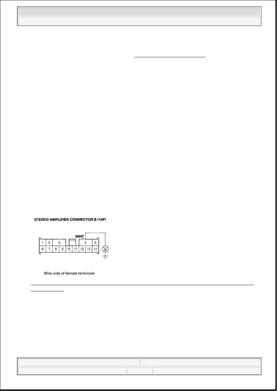
11. Measure the voltage between stereo amplifier connector B (14P) No. 4 terminal and body ground. 

Fig. 40: Measuring Voltage Between Stereo Amplifier Connector B (14P) No. 4 Terminal And 
Body Ground
 
Courtesy of AMERICAN HONDA MOTOR CO., INC. 

Is there battery voltage?  

YES - Go to step 12. 

NO - Repair open in the wire between fuse No. 2 (30A) in the passenger's under-dash fuse/relay box 
and stereo amplifier connector B (14P) No. 4 terminal. 

12. Turn the ignition switch to ON (II).  

NOTE:

Eject all the CDs before removing the audio unit and CD changer to 
prevent damaging the CD player's load mechanism.


2007 Acura RL 

2005-08 ACCESSORIES AND EQUIPMENT Audio System - RL


me 


Friday, June 05, 2009 3:53:07 PM

Page 42 

© 2005 Mitchell Repair Information Company, LLC. 

13. Measure the voltage between stereo amplifier connector C (23P) No. 19 terminal and body ground. 

Fig. 41: Measuring Voltage Between Stereo Amplifier Connector C (23P) No. 19 Terminal And 
Body Ground
 
Courtesy of AMERICAN HONDA MOTOR CO., INC. 

Is there battery voltage?  

YES - Go to step 14. 

NO - Repair open in the wire between the stereo amplifier connector C (23P) No. 19 terminal and 
audio unit connector A (20P) No. 1 terminal. 

14. Reconnect stereo amplifier connectors A (20P), B(14P), and C (23P).  

15. Check for continuity between stereo amplifier connector B (14P) No. 3 terminal and body ground. 

Fig. 42: Checking Continuity Between Stereo Amplifier Connector B (14P) No. 3 Terminal And 
Body Ground
 
Courtesy of AMERICAN HONDA MOTOR CO., INC. 

Is there continuity?  

YES - Go to step 16. 

NO - Repair open in the wire between stereo amplifier connector B (14P) No. 3 terminal and body 
ground (G652). 

16. Disconnect stereo amplifier connectors B (14P), and C (23P).  

17. Measure the resistance of stereo amplifier connectors B (14P) and C (23P) according to the table. 


2007 Acura RL 

2005-08 ACCESSORIES AND EQUIPMENT Audio System - RL


me 


Friday, June 05, 2009 3:53:07 PM

Page 43 

© 2005 Mitchell Repair Information Company, LLC. 

SPEAKER TERMINAL SPECIFICATIONS

Fig. 43: Identifying Stereo Amplifier Connectors B (14P) And C (23P) Wire Side of Female 
Terminals
 
Courtesy of AMERICAN HONDA MOTOR CO., INC. 

Is there more than 4 ohms?  

YES - Go to step 18. 

NO - Repair open in the wire between the stereo amplifier and the speaker. 

18. Disconnect the speaker 2P connector.  

19. Check for continuity between the stereo amplifier connector B (14P) and C (23P) terminals and body 

ground according to the table. 

SPEAKER TERMINAL SPECIFICATIONS 

Speaker

Terminal Wire color

Driver's door speaker. Left front tweeter

C23 (+)

LT BLU

C10 (-)

LT GRN

Passenger's door speaker, Right front tweeter

B6 (+)

LT GRN

B1 (-)

GRY

Front center speaker

C22 (+)

BLU

C9 (-)

PNK

Right rear speaker

B8 (+)

BLU

B9 (-)

ORN

Right rear twiddler

B12 (+)

GRY

B13 (-)

BLU

Subwoofer

B5 (+)

BRN

B14 (-)

GRN

Left rear twiddler

B10 (+)

PUR

B11 (-)

LT BLU

Left rear speaker

B7 (+)

GRY

B2 (-)

BRN

Speaker

Terminal Wire color


2007 Acura RL 

2005-08 ACCESSORIES AND EQUIPMENT Audio System - RL


me 


Friday, June 05, 2009 3:53:07 PM

Page 44 

© 2005 Mitchell Repair Information Company, LLC. 

Fig. 44: Identifying Stereo Amplifier Connectors B (14P) And C (23P) Wire Side of Female 
Terminals
 
Courtesy of AMERICAN HONDA MOTOR CO., INC. 

Is there continuity?  

YES - Go to step 20. 

NO - Repair short in the wire between the stereo amplifier and the appropriate speaker. 

20. Reconnect the 2P connector(s) to the speaker(s).  

21. Disconnect audio unit connector A (20P) and audio unit connector B (32P). 

22. Disconnect amplifier connector A (26P).  

23. Check for continuity between audio unit connector A (20P) and body ground according to the table. 

Driver's door speaker, Left front tweeter

C23 (+)

LT BLU

C10 (-)

LT GRN

Front passenger's door speaker, Right front tweeter B6 (+)

LT

GRN

B1 (-)

GRY

Left rear speaker

B7 (+)

GRN

B2 (-)

BRN

Right rear speaker

B8 (+)

BLU

B9 (-)

ORN

Left rear twiddler speaker

B10 (+)

PUR

B11 (-)

LT BLU

Right rear twiddler speaker

B12 (+)

GRY

B13 (-)

BLU

Front center speaker

C22 (+)

BLU

C9 (-)

PNK

Subwoofer

B5 (+)

BRN

B14 (-)

GRN

NOTE:

Eject all the CDs before removing the audio unit and CD changer to 
prevent damaging the CD player's load mechanism.


2007 Acura RL 

2005-08 ACCESSORIES AND EQUIPMENT Audio System - RL


me 


Friday, June 05, 2009 3:53:07 PM

Page 45 

© 2005 Mitchell Repair Information Company, LLC. 


Content   ..  189  190  191  192   ..