Acura RL. Manual - part 81


  Index      Acura     Acura RL - service repair manual 2005-2008 year


Search            


Content   ..  79  80  81  82   ..


Acura RL. Manual - part 81


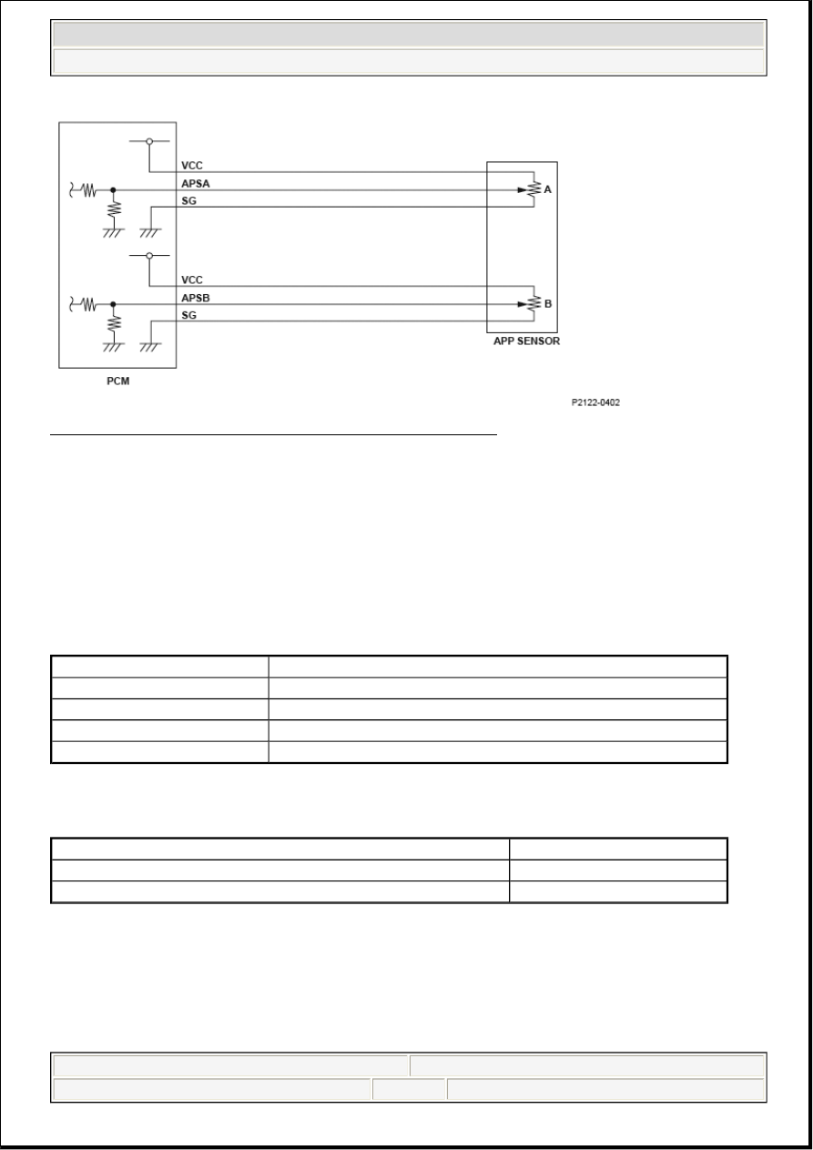
Fig. 261: Accelerator Pedal Position Sensor B - Circuit Diagram 

General Description 

Accelerator pedal position (APP) sensor B is a part of the electronic throttle control system, and it is used to 
convert the position of the accelerator pedal into electrical signals. Based on these signals, the powertrain 
control module (PCM) controls the throttle actuator so that the throttle position agrees with the accelerator 
pedal position. If the signal voltage from APP sensor B is a set value or more, the PCM detects a 
malfunction and stores a DTC. 

Monitor Execution, Sequence, Duration, DTC Type, OBD Status 

MONITOR DESCRIPTION CHART 

Enable Conditions 

ENABLE CONDITIONS 

Malfunction Threshold 

The APP sensor B output voltage is 4.0 V or more for at least 0.2 seconds. 

Diagnosis Details 

Conditions for illuminating the MIL 

Execution

Continuous

Sequence

None

Duration

0.2 seconds or more

DTC Type

One drive cycle, MIL ON

OBD Status

N/A

Condition


State of the engine

Running

No active DTCs

P2127


2007 Acura RL 

2007 ENGINE PERFORMANCE Advanced Diagnostics - RL


me 


Friday, June 05, 2009 2:32:07 PM

Page 321  © 2005 Mitchell Repair Information Company, LLC. 

When a malfunction is detected, the MIL comes on and the DTC and the freeze frame data are stored in the 
PCM memory. 

Conditions for clearing the MIL 

The MIL will be cleared if the malfunction does not recur during three consecutive trips in which the 
diagnostic runs. 

The MIL, the DTC, and the freeze frame data can be cleared by using the scan tool Clear command or by 
disconnecting the battery. 

DTC P2135 (7): ADVANCED DIAGNOSTICS 

DTC P2135: THROTTLE POSITION (TP) SENSOR A/B VOLTAGE INCORRECT 
CORRELATION 


2007 Acura RL 

2007 ENGINE PERFORMANCE Advanced Diagnostics - RL


me 


Friday, June 05, 2009 2:32:07 PM

Page 322  © 2005 Mitchell Repair Information Company, LLC. 

Fig. 262: Throttle Position (TP) Sensor A/B - Circuit Diagram


2007 Acura RL 

2007 ENGINE PERFORMANCE Advanced Diagnostics - RL


me 


Friday, June 05, 2009 2:32:07 PM

Page 323  © 2005 Mitchell Repair Information Company, LLC. 

Fig. 263: Throttle Position (TP) Sensor Output Voltage Graph 

General Description 

The electronic throttle control system (ETCS) controls the throttle valve opening. The system is composed 
of the throttle actuator, the throttle valve, throttle position (TP) sensors A and B, the throttle actuator control 
module, the throttle actuator control module relay, the accelerator pedal position (APP) sensor, and the 
powertrain control module (PCM). 

The APP sensor is operated via the throttle cable to determine the accelerator opening value when the driver 
presses the accelerator pedal. The accelerator pedal opening value is converted to a signal in the APP sensor 
and transmitted to the PCM to compute the target position. The target position signal is then transmitted to 
the throttle actuator control module. The throttle actuator control module determines the throttle valve target 
position according to the signal received and operates the throttle actuator to move the throttle valve to the 
target position. The actual throttle valve position is determined by TP sensor A installed in the throttle body.

The throttle actuator control module compares the voltages and the throttle valve positions of TP sensor A 
and TP sensor B. If the difference of the voltages or the throttle valve positions is the fixed value or less for 
a set time, the throttle actuator control module detects a malfunction and the malfunction data is transmitted 
to the PCM. When the PCM receives the malfunction data from the throttle actuator control module, the 
PCM detects a malfunction in the relationship between TP sensor A and TP sensor B, and stores a DTC. 

Monitor Execution, Sequence, Duration, DTC Type, OBD Status 

MONITOR DESCRIPTION CHART 

Execution

Continuous

Sequence

None

Duration

0.2 seconds or more

DTC Type

One drive cycle, MIL ON


2007 Acura RL 

2007 ENGINE PERFORMANCE Advanced Diagnostics - RL


me 


Friday, June 05, 2009 2:32:07 PM

Page 324  © 2005 Mitchell Repair Information Company, LLC. 


Content   ..  79  80  81  82   ..