Acura RL. Manual - part 75
 

  Index      Acura     Acura RL - service repair manual 2005-2008 year


Search            


Content   ..  73  74  75  76   ..


Acura RL. Manual - part 75


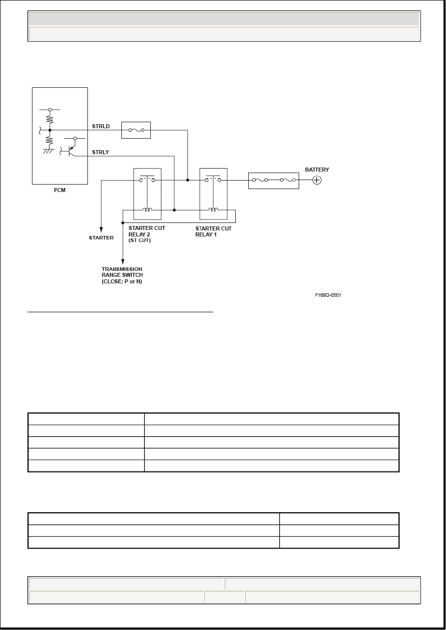
DTC P16BF: STARTER RELAY STRLY CIRCUIT MALFUNCTION

Fig. 244: Starter Relay STRLY Circuit Diagram 

General Description 

The PCM compares the signal of the drive command to the starter and the return signal from the starter cut 
relay. When the signal of the drive command to the starter and the return signal from the starter cut relay do 
not coincide for a set time or more, the PCM detects a malfunction and a DTC is stored. 

Monitor Execution, Sequence, Duration, DTC Type, OBD Status 

MONITOR DESCRIPTION CHART 

Enable Conditions 

ENABLE CONDITIONS 

Malfunction Threshold 

Execution

Continuous

Sequence

None

Duration

5 seconds or more

DTC Type

One drive cycle, MIL OFF

OBD Status

N/A

Condition


Ignition switch

ON

State of the engine

Running


2007 Acura RL 

2007 ENGINE PERFORMANCE Advanced Diagnostics - RL


me 


Friday, June 05, 2009 2:32:06 PM

Page 297  © 2005 Mitchell Repair Information Company, LLC. 

The signal of the drive command from the PCM to the starter and the return signal from the starter cut relay 
do not coincide for at least 5 seconds. 

Driving Pattern 

Start the engine. Hold the engine speed at 3,000 rpm without load (in Park or neutral) until the radiator fan 
comes on, then let it idle. 

Diagnosis Details 

Conditions for illuminating the indicator 

When a malfunction is detected, the DTC and the freeze frame data are stored in the PCM memory. The 
MIL does not come on. 

Conditions for clearing the DTC 

The DTC and the freeze frame data can be cleared by using the scan tool Clear command or by 
disconnecting the battery. 

DTC P1717 (62): ADVANCED DIAGNOSTICS 

DTC P1717: OPEN IN TRANSMISSION RANGE SWITCH ATP RVS SWITCH CIRCUIT 

Fig. 245: Transmission Range Switch ATP RVS Switch Circuit Diagram 

TRANSMISSION RANGE SWITCH CONTACT POINT INPUT MATRIX 

Shift lever position

Input per switch

P

R

N

D

D3

FWD

RVS

P

o

X

X

X

X

X

o

R

X

o

X

X

X

X

o


2007 Acura RL 

2007 ENGINE PERFORMANCE Advanced Diagnostics - RL


me 


Friday, June 05, 2009 2:32:06 PM

Page 298  © 2005 Mitchell Repair Information Company, LLC. 

General Description 

The transmission range switch is attached to the control shaft. Operating the shift lever makes the control 
shaft rotate via the shift cable. The A/T gear position indicator indicates which position is selected according 
to the Low/High signal combinations which vary based on shift lever position. The control shaft changes the 
position of the transmission range switch, activates the manual valve, and switches hydraulic pressure to 
shift the transmission through forward/neutral/reverse. The transmission range switch signal is used to 
determine the shift schedule. The voltage is 12 V (High) at the powertrain control module (PCM) input 
terminal when each transmission range switch position is open, and it is 0 V (Low) when each switch is 
closed. If the RVS switch is OPEN with the shift lever in the R position while shifting between the P, R, and 
N positions, the PCM detects a RVS switch OPEN failure and a DTC is stored. 

Monitor Execution, Sequence, Duration, DTC Type, OBD Status 

MONITOR DESCRIPTION CHART 

Enable Conditions 

ENABLE CONDITIONS 

Malfunction Threshold 

No RVS signal is detected with the shift lever in the R position while shifting between the P, R, and N 
positions. 

Driving Pattern 

1. Start the engine, and shift to the P, R, and N positions.  

2. Shift to the R position, and wait for at least 2 seconds.  

Diagnosis Details 

Conditions for illuminating the MIL 

When a malfunction is detected, the MIL comes on and the DTC and the freeze frame data are stored in the 
PCM memory. 

N

X

X

o

X

X

X

o

D

X

X

X

o

X

o

X

D3

X

X

X

X

o

o

X

o: Closed X: Open

Execution

Continuous

Sequence

None

Duration

2 seconds or more

DTC Type

One drive cycle, MIL ON, D indicator blinks

OBD Status

PASSED/FAILED/NOT COMPLETED (STILL TESTING)

Condition

Minimum

Maximum

Battery voltage

11.0 V

-

No active DTCs

P0705, P0812


2007 Acura RL 

2007 ENGINE PERFORMANCE Advanced Diagnostics - RL


me 


Friday, June 05, 2009 2:32:06 PM

Page 299  © 2005 Mitchell Repair Information Company, LLC. 

Conditions for clearing the MIL 

The MIL will be cleared if the malfunction does not recur during three consecutive trips in which the 
diagnostic runs. 

The MIL, the DTC, and the freeze frame data can be cleared by using the scan tool Clear command or by 
disconnecting the battery. 

DTC P1743 (45): ADVANCED DIAGNOSTICS 

DTC P1743: PROBLEM IN SHIFT CONTROL SYSTEM; SHIFT VALVE E STUCK OFF 

Fig. 246: Shift Control System; Shift Valve E - Operation Diagram


2007 Acura RL 

2007 ENGINE PERFORMANCE Advanced Diagnostics - RL


me 


Friday, June 05, 2009 2:32:06 PM

Page 300  © 2005 Mitchell Repair Information Company, LLC. 


Content   ..  73  74  75  76   ..