Acura RL. Manual - part 58
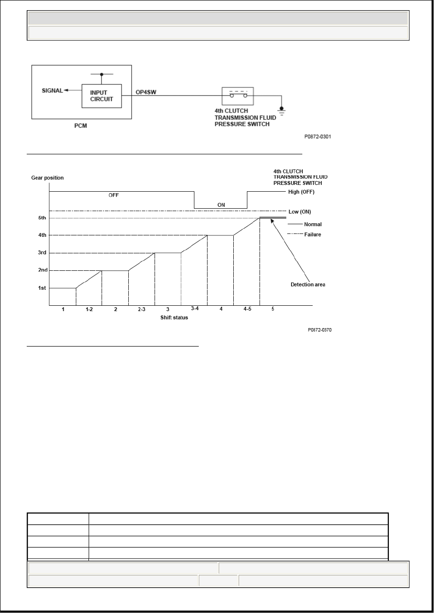
Fig. 185: 4th Clutch Transmission Fluid Pressure Switch Circuit Diagram
Fig. 186: Gear Position VS Shift Status Graph
General Description
The 4th clutch transmission fluid pressure switch is installed in the hydraulic pressure circuit to the 4th
clutch. When hydraulic pressure is supplied to the 4th clutch, the switch is turned ON. When hydraulic
pressure is not supplied to the 4th clutch, the switch is turned OFF. The signal from the 4th clutch
transmission fluid pressure switch is input to the powertrain control module (PCM). The PCM detects the
hydraulic pressure supply conditions at the gear change to 4th gear (3rd --> 4th, 5th --> 4th) to reduce the
shock that occurs at the gear change.
If the 4th clutch transmission fluid pressure switch is ON while driving, and the speed ratio of the output
shaft (countershaft) to input shaft (mainshaft) is other than 4th gear (the ratio is Neutral or 5th), the PCM
detects a 4th clutch transmission fluid pressure switch failure and stores DTC.
Monitor Execution, Sequence, Duration, DTC Type, OBD Status
MONITOR DESCRIPTION CHART
Execution
Continuous
Sequence
None
Duration
2 seconds or more
DTC Type
One drive cycle, MIL OFF, D indicator blinks
2007 Acura RL
2007 ENGINE PERFORMANCE Advanced Diagnostics - RL
me
Friday, June 05, 2009 2:32:05 PM
Page 229 © 2005 Mitchell Repair Information Company, LLC.