Acura CSX. Manual - part 693
02
−
−
−
−
YES
NO
YES
NO
24-89
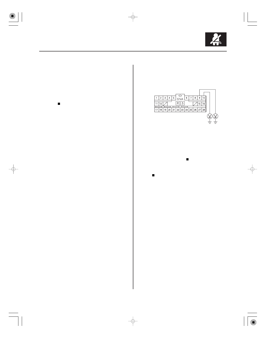
SRS UNIT CONNECTOR B (28P)
8. Read the DTC (see page 24-22).
Go to step 9.
Short to power in the front passenger’s seat
belt buckle tensioner; replace the front passenger’s
seat belt buckle (see page 24-6), then clear the
DTC.
9. Turn the ignition switch to LOCK (0). Disconnect the
negative cable from the battery, then wait at least 3
minutes.
10. Disconnect both side airbag 2P connectors (see
step 4 on page 24-20) and the driver’s seat belt
buckle tensioner 4P connector (see step 8 on page
24-21).
11. Disconnect SRS unit connector B (28P) from the
SRS unit (see step 9 on page 24-21).
12. Disconnect the simulator lead from the floor wire
harness.
13. Reconnect the negative cable to the battery.
14. Turn the ignition switch to ON (II).
15. Measure the voltage between body ground and
SRS unit connector B (28P) terminals No. 9 and
No. 10, individually. There should be less than 0.2 V.
Faulty SRS unit or poor connection at SRS
unit connector B (28P) and the SRS unit. Check the
connection; if the connection is OK, replace the
SRS unit (see page 24-203).
Short to power in the floor wire harness;
replace the floor wire harness, then clear the
DTC.
Wire side of female terminals
Is DT C 28-8x indicated?
Is the voltage as specif ied?
08/08/21 13:57:00 61SNR030_240_0089