Acura CSX. Manual - part 643
 

  Index      Acura     Acura CSX - P/NO. 61SNR03 - service repair manual 2006-2009 year


Search            


Content   ..  641  642  643  644   ..


Acura CSX. Manual - part 643


*05

Yaw Rate Sensor

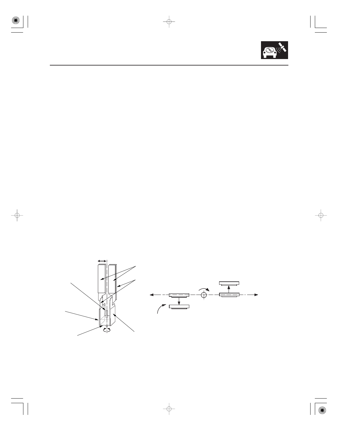
Sensor Element Structure

Oscillation Gyro Principles

Operation

23-283

Enlarged view of sensor element

DETECTING PIEZOELECTRIC
PARTS

OSCILLATORS

SUPPORT PIN

DRIVING
PIEZOELECTRIC
PART

METAL BLOCK

MONITORING PIEZOELECTRIC
PART

Bend

Oscillation

Coriolis force

Turn to
right

Coriolis force

Oscillation

Sensor element top view

The yaw rate sensor (located in the navigation unit) detects the direction change (angular speed) of the vehicle. The
sensor is an oscillation gyro built into the navigation unit.

The sensor element is shaped like a tuning fork, and it consists of the piezoelectric parts, the metal block, and the
support pin. There are four piezoelectric parts: one to drive the oscillators, one to monitor and maintain the oscillation
at a regular frequency, and two to detect angular velocity. The two oscillators, which have a 90-degree twist in the
center, are connected at the bottom by the metal block and supported by the support pin. A detection piezoelectric part
is attached to the top of each oscillator. The driving piezoelectric part is attached to the bottom of one oscillator, and
the monitoring piezoelectric part is attached to the bottom of the other oscillator.

The piezoelectric parts have electric/mechanical transfer characteristics. They bend vertically when voltage is applied
to both sides of the parts, and voltage is generated between both sides of the piezoelectric parts when they are bent by
an external force. The oscillation gyro functions by utilizing this characteristic of the piezoelectric parts and Coriolis
force. (Coriolis force deflects moving objects as a result of the earth’s rotation.) In the oscillation gyro, this force
moves the sensor element when angular velocity is applied.

1. The driving piezoelectric part oscillates the oscillator by repeatedly bending and returning when an AC voltage of

6 kHz is applied to the part. The monitoring-side oscillator resonates because it is connected to the driving-side
oscillator by the metal block.

2. The monitoring piezoelectric part bends in proportion to the oscillation and outputs voltage (the monitor signal).

The navigation unit control circuit controls the drive signal to stabilize the monitor signal.

3. When the vehicle is stopped, the detecting piezoelectric parts oscillate right and left with the oscillators, but no

signal is output because the parts are not bent (no angular force).

4. When the vehicle turns to the right, the sensor element moves in a circular motion with the right oscillator

bending forward and the left oscillator bending rearward. The amount of forward/rearward bend varies according
to the angular velocity of the vehicle.

5. The detecting piezoelectric parts output voltage (the yaw rate signal) according to the amount of bend. The

amount of vehicle direction change is determined by measuring this voltage.

08/08/21 14:15:43 61SNR030_230_0286

*06

Global Positioning System (GPS)

Position Detection Image with GPS Satellite

Precision of GPS

GPS ICON

COLOR

NUMBER OF

SATELLITES

CONDITION

DESCRIPTION

GPS Antenna

GPS Receiver and Clock

23-284

Navigation System

The global positioning system (GPS) enables the navigation system to determine the current position of the vehicle by
using the signals transmitted from the satellites in orbit around the earth. The satellites transmit the satellite
identification signal, orbit information, transmission time signal, and other information. When the GPS receiver
receives a signal from four or more satellites simultaneously, it calculates the current position of the vehicle based on
the distance to each satellite and the satellite’s positions in its respective orbit.

The precision of the GPS varies according to the number of satellites from which signals are received and the view of
the sky. The accuracy is indicated by the color and shape of the GPS icon shown on the display.

No GPS icon

None

Faulty reception

The GPS can’t be utilized due to a faulty
GPS receiver, open in the wire, or other
fault or interference.

White GPS icon

2 or less

Impossible to detect vehicle
position

GPS function is normal. The satellite
signals received by the GPS are too few to
detect the vehicle position.

Green GPS icon

3

Vehicle position detectable in
2 dimensions

The longitude and latitude of the vehicle
position can be detected. (Less precise
than detection in three dimensions)

4 or more

Vehicle position detectable in
3 dimensions (elevation
displayed)

The longitude, latitude and the altitude of
the vehicle position can be detected. (More
precise than detection in two dimensions)

The GPS antenna amplifies and transmits the signals received from the satellites to the GPS receiver.

The GPS receiver is built into the navigation unit. It calculates the vehicle position by receiving the signal from the GPS
antenna. The current time vehicle position and signal reception condition is transmitted from the GPS receiver to the
navigation unit to adjust vehicle position.

08/08/21 14:15:43 61SNR030_230_0287

Navigation Unit

Calculation of Vehicle Position

Map Matching Tuning

GPS Tuning

Distance Tuning

Route Guidance

Audio Guidance

DVD-ROM

23-285

The navigation unit calculates the vehicle position and guides you to the destination. The unit performs map matching
correction, GPS correction, and distance tuning. It also controls the menu functions and the DVD-ROM drive, and
interprets voice commands. With control of all these items, the navigation unit makes the navigation picture signal,
then it transmits the signal to the navigation display and audio driving instructions to the audio unit.

The navigation unit calculates the vehicle position (the driving direction and the current position) by receiving the
directional change signals from the yaw rate sensor and the travel distance signals from the PCMs vehicle speed pulse
(VSP) signal.

The map matching tuning is accomplished by indicating the vehicle position on the roads on the map. The map data
transmitted from the DVD-ROM is checked against the vehicle position data, and the vehicle position is indicated on
the nearest road. Map matching tuning does not occur when the vehicle travels on a road not shown on the map, or
when the vehicle position is far away from a road on the map.

The GPS tuning is accomplished by indicating the vehicle position as the GPS’s vehicle position. The navigation unit
compares its calculated vehicle position data with the GPS vehicle position data. If there is large difference between
the two, the indicated vehicle position is adjusted to the GPS vehicle position.

The distance tuning reduces the difference between the travel distance signal from the VSP and the distance data on
the map. The navigation unit compares its calculated vehicle position data with the GPS vehicle position data. The
navigation unit then decreases the tuning value when the vehicle position is always ahead of the GPS vehicle position,
and it increases the tuning value when the vehicle position is always behind the GPS vehicle position.

The navigation unit can calculate different routes to a selected destination. You have five options:

• Direct Route

Calculate a route that is the most direct.

• Easy Route

Calculate a route that minimizes the number of turns needed.

• Minimize Freeways

Calculate a route that avoids freeway travel. If that is not possible, keep the amount of

freeway travel to a minimum.

• Minimize Toll Roads

Calculate a route that avoids, or minimizes travel on toll roads.

• Maximize Freeways

Calculate a route that uses freeways as much as possible.

The navigation unit transmits audio driving instructions before entering an intersection or passing a junction.
The audio instructions come through the audio unit to the front speakers.

NOTE: The front speakers are muted whenever the navigation system is giving guidance commands, and all of the
speakers are muted when the voice control system is being used.

The map data (including all scale rates) is stored in the DVD-ROM. The map data includes:

• Road distances, road widths, speed limits, traffic regulations, passing time at junction, distances to junctions, and

the driving instructions for audio guidance.

• Latitude and longitude GPS.

08/08/21 14:15:43 61SNR030_230_0288

*07

*08

Audio Unit (Built in the navigation unit)

Navigation Display

Microphone

Navigation TALK Button

Navigation BACK Button

23-286

Navigation System

NAVIGATION TALK BUTTON

NAVIGATION BACK BUTTON

The audio unit receives the audio driving instructions from the navigation unit, and transmits the instructions through
the front speakers even when the audio system is in use.

The navigation display uses liquid crystal display (LCD). The LCD is a 6.5-inch-diagonal, thin film transistor (TFT),
stripe type with 65,536 color. The color film and fluorescent light are laid out on the back of the liquid crystal film. The
touch sensor on the front of the LCD consists of a touch sensitive resistive membrane with an infinite number of
possible touch locations.

The microphone (on the ceiling, near the front map light) receives voice commands and transmits them to the
navigation unit for interpretation.

Activates the voice control system in the navigation unit to accept voice commands.

Returns the display to the previous screen (similar function as the CANCEL button).

08/08/21 14:15:44 61SNR030_230_0289


Content   ..  641  642  643  644   ..