Acura CSX. Manual - part 632


  Index      Acura     Acura CSX - P/NO. 61SNR03 - service repair manual 2006-2009 year


Search            


Content   ..  630  631  632  633   ..


Acura CSX. Manual - part 632


*21

SNR9ANKJ10300000000FAAT33

USB device does not function (without
navigation)

YES

NO

YES

NO

USB adapter unit

connector

USB adapter

connector

YES

NO

YES

NO

23-241

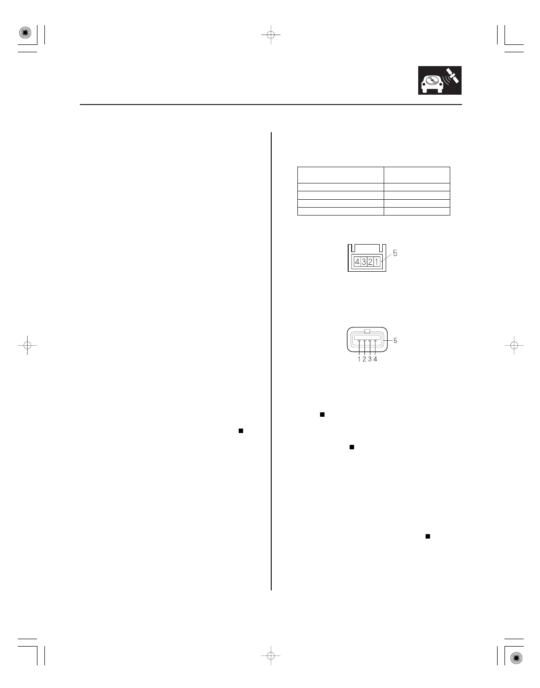
USB ADAPTER UNIT CONNECTOR B (5P)

USB ADAPTER 5P CONNECTOR

NOTE:

• Check the vehicle battery condition first.
• Check the connectors for poor connections or loose

terminals.

• Check the USB device requirement:

– Mass-storage class ready digital audio player with

USB 2.0 port

– More than 256 MB of RAM
– Supports MP3, WMA, and AAC (encoded with the i-

Tunes) files, DRM files are not supported

1. Turn the ignition switch to ON (II) and turn on the

audio unit.

2. Push the AUX button to select USB mode.

Go to step 3.

Go to step 7.

3. Turn the ignition switch to LOCK (0).

4. Connect the client’s USB device to a known-good

vehicle that equipped with the USB adapter and
check the USB device operation.

Go to step 5.

USB device is faulty. Also check the USB

cable and USB adapter connector condition.

5. Disconnect USB adapter unit connector B (5P).

6. Check for continuity between terminals of USB

adapter connector B (5P) and the USB adapter 5P
connector according to the table.

B1

1

B2

2

B3

3

B4

4

Replace the USB adapter unit (see page

23-258).

Open in the wire(s) between the USB adapter

unit and the USB adapter. Replace the affected
shielded harness.

7. Turn the ignition switch to LOCK (0).

8. Check that the audio unit connectors and the USB

adapter unit connectors properly connected.

Go to step 9.

Connect the connectors and recheck.

Terminal side of female terminals

Terminal side of male terminals

Is USB NO DAT A displayed?

Is the USB device wor king pr oper ly?

Is ther e continuity?

Ar e the connector s pr oper ly connected?

08/08/21 14:14:12 61SNR030_230_0244

*22

*23

*24

*39

YES

NO

YES

NO

YES

NO

YES

NO

23-242

Audio System

USB ADAPTER UNIT CONNECTOR A (14P)

B (BLU)

USB ADAPTER UNIT CONNECTOR A (14P)

GND (BLK)

USB ADAPTER UNIT CONNECTOR A (14P)

SYS ACC (LT BLU)

AUDIO UNIT CONNECTOR E (14P)

SYS ACC (LT BLU)

9. Measure the voltage between body ground and

USB adapter unit connector A (14P) terminal No. 1.

Go to step 10.

Repair open in the wire between the audio

unit and the USB adapter unit.

10. Turn the ignition switch to ON (II).

11. Measure the voltage between body ground and

USB adapter unit connector A (14P) terminal
No. 11.

Go to step 12.

Repair open or high resistance in the wire

between the audio unit and the USB adapter unit.

12. Turn the ignition switch to LOCK (0).

13. Measure the voltage between body ground and

USB adapter unit connector A (14P) terminal No. 2.

Go to step 15.

Go to step 14.

14. Measure the voltage between body ground and

audio unit connector E (14P) terminal No. 2.

Repair open or short in the wire(s) between

the audio unit and the USB adapter unit.

Substitute a known-good audio unit (see page

23-256), and recheck. If 10 V or more are present,
replace the original audio unit.

Wire side of female terminals

Wire side of female terminals

Wire side of female terminals

Wire side of female terminals

Is ther e batter y voltage?

Is ther e less than 0.1 V ?

Is ther e 10 V or mor e pr esent?

Is ther e 10 V or mor e pr esent?

08/08/21 14:14:12 61SNR030_230_0245

*40

*27

YES

NO

YES

NO

23-243

AUDIO UNIT CONNECTOR E (14P)

SYS ACC (LT BLU)

AUDIO UNIT CONNECTOR E (14P)

GA-NET BUS
(PNK)

GA-NET BUS
(BLU)

15. Turn the ignition switch to ON (II).

16. Measure the voltage between body ground and

audio unit connector E (14P) terminal No. 2.

Substitute a known-good audio unit

(see page 23-256), and recheck. If 10 V or more are
present, replace the original audio unit.

Go to step 17.

17. Turn the ignition switch to LOCK (0).

18. Disconnect audio unit connector E (14P) and USB

adapter unit connector A (14P).

19. Check for continuity between body ground and

audio unit connector E (14P) terminals No. 9 and
No. 10 individually.

Short to body ground in the wires between

the audio unit and the USB adapter unit. Replace
the affected shielded harness.

Go to step 20.

Wire side of female terminals

Wire side of female terminals

Is ther e 10 V or mor e pr esent?

Is ther e continuity?

08/08/21 14:14:13 61SNR030_230_0246

*28

*29

From terminal

(wire color)

To terminals (wire color)

YES

NO

Audio unit

connector

USB adapter

unit connector

Wire color

YES

NO

23-244

Audio System

AUDIO UNIT CONNECTOR E (14P)

AUDIO UNIT CONNECTOR E (14P)

USB ADAPTER UNIT CONNECTOR A (14P)

20. Check for continuity between the terminals of audio

unit connector E (14P) according to the table.

E3 (BRN)

E9 (BLU), E10 (PNK)

E9 (BLU)

E10 (PNK)

Short in the wires between the audio unit

and the USB adapter unit. Replace the affected
shielded harness.

Go to step 21.

21. Check for continuity between the terminals of audio

unit connector E (14P) and USB adapter unit
connector A (14P) according to the table.

E9

A9

(BLU)

E10

A10

(PNK)

Substitute a known-good USB adapter unit

(see page 23-258), then reconnect all of the
connectors and recheck. If the symptom/indication
goes away, replace the original USB adapter unit. If
the symptom/indication is still present, replace the
audio unit (see page 23-256).

Open in the wire(s) between the audio unit

and the USB adapter unit. Replace the affected
shielded harness.

Wire side of female terminals

Wire side of female terminals

Wire side of female terminals

Is ther e continuity between any of the ter minals?

Is ther e continuity?

08/08/21 14:14:13 61SNR030_230_0247


Content   ..  630  631  632  633   ..