Acura CSX. Manual - part 579
*02
*03
*04
+
+
+
+
−
−
−
−
−
−
−
−
YES
NO
YES
NO
YES
NO
YES
NO
23-33
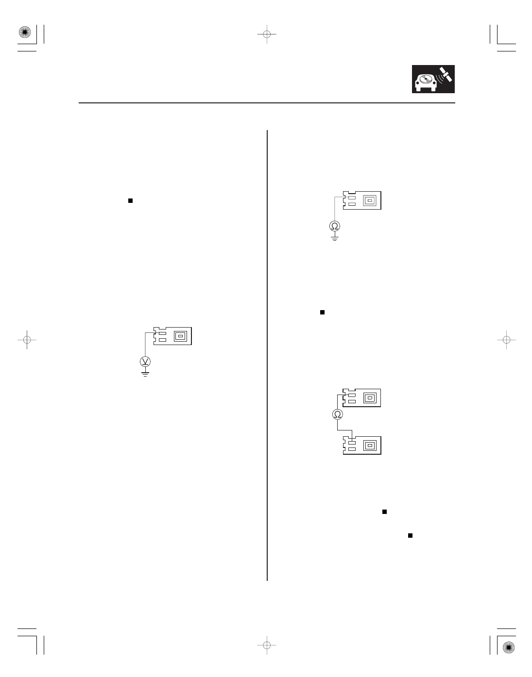
AM/FM ANTENNA AMPLIFIER 3P CONNECTOR
ANT
B
AM/FM ANTENNA AMPLIFIER 3P CONNECTOR
ANT
B
AUDIO UNIT CONNECTOR G (3P)
AM/FM ANTENNA AMPLIFIER 3P CONNECTOR
ANT
B
ANT
B
10. Remove the audio unit (see page 23-80). Check that
the antenna lead is properly connected.
Go to step 10.
Reconnect the connector, and recheck the
function.
11. Disconnect the antenna cable 3P connector from
the AM/FM antenna amplifier (see page 23-87).
12. Turn the ignition switch to ON (II).
13. Turn on the audio unit.
14. Measure the voltage between the AM/FM antenna
lead connector terminal No. 3 at the AM/FM
antenna amplifier and body ground.
Go to step 19.
Go to step 15.
15. Turn the ignition switch to LOCK (0).
16. Disconnect audio unit connector G (3P).
17. Check for continuity between the AM/FM antenna
amplifier connector (3P) terminal No. 3 and body
ground.
Repair short to body ground in the wire
between the audio unit and the AM/FM antenna
amplifier.
Go to step 18.
18. Check for continuity between audio unit connector
G (3P) terminal No. 3 and the AM/FM antenna
amplifier 3P connector terminal No. 3.
Substitute a known-good audio unit
(see page 23-80), and recheck.
Repair open in the wire between the audio
unit and the AM/FM antenna amplifier.
Terminal side of female terminals
Terminal side of female terminals
Terminal side of female terminals
Terminal side of female terminals
Is it connected pr oper ly?
Is ther e batter y voltage?
Is ther e continuity?
Is ther e continuity?
08/08/21 14:04:39 61SNR030_230_0036