Acura CSX. Manual - part 403
+
01
SNR9AC7K801000R1113FAAT00
+
+
+
+
−
−
−
−
DTC 11-13:
DTC 13-13:
DTC 15-13:
DTC 17-13:
YES
NO
DTC
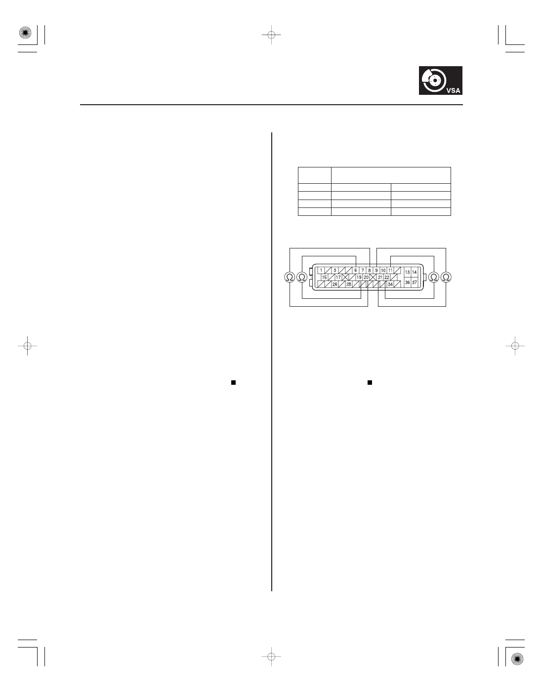
VSA Modulator-control Unit 37P
Connector Terminal
YES
NO
19-117
DTC Troubleshooting
VSA MODULATOR-CONTROL UNIT 37P CONNECTOR
FR
B (GRN)
RL-GND (PUR)
FR-GND (PNK)
RR
B (LT GRN)
RL
B (YEL)
FL
B (WHT)
RR-GND (BLU)
FL-GND (RED)
Right-front Wheel Speed Sensor
Circuit Malfunction
Left-front Wheel Speed Sensor
Circuit Malfunction
Right-rear Wheel Speed Sensor
Circuit Malfunction
Left-rear Wheel Speed Sensor
Circuit Malfunction
1. Turn the ignition switch to ON (II).
2. Clear the DTC with the HDS.
3. Turn the ignition switch to LOCK (0), then turn it to
ON (II) again.
4. Check for DTCs with the HDS.
Go to step 5.
Intermittent failure, the system is OK at this
time. Check for loose terminals between the wheel
speed sensor 2P connector and the VSA modulator-
control unit 37P connector. Refer to intermittent
failures troubleshooting (see page 19-98).
5. Turn the ignition switch to LOCK (0).
6. Disconnect the VSA modulator-control unit 37P
connector (see step 2 on page 19-171).
7. Disconnect the appropriate wheel speed sensor 2P
connector.
8. Check for continuity between the appropriate VSA
modulator-control unit 37P connector wheel speed
sensor
B and GND terminals (see table).
11-13
No. 19
No. 6
13-13
No. 22
No. 11
15-13
No. 9
No. 21
17-13
No. 20
No. 8
Repair short in the wires between the
appropriate wheel speed sensor and the VSA
modulator-control unit.
Go to step 9.
Wire side of female terminals
Is DT C 11-13, 13-13, 15-13, and/ or 17 -13
indicated?
Is ther e continuity?
08/08/21 15:04:57 61SNR030_190_0117