Acura CSX. Manual - part 351
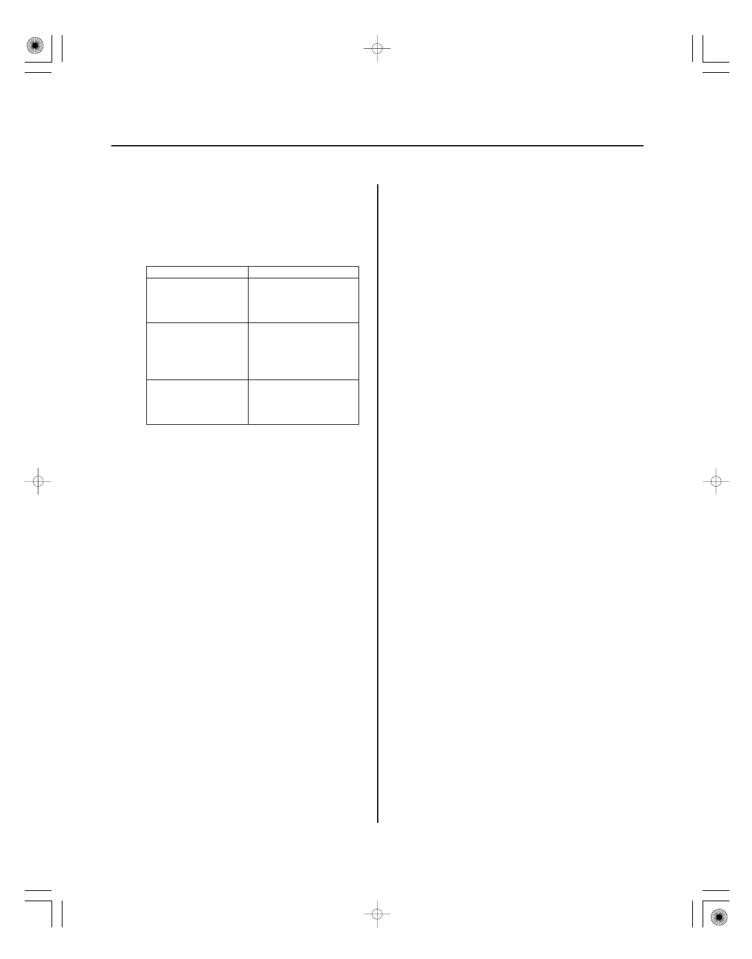
Symptom
Probable cause
17-78
EPS Components
34. Install the steering wheel (see page 17-8).
35. With the tires raised off the ground (vehicle on a
lift), check for the following symptoms by turning
the steering wheel fully to the right and left several
times.
Rubbing sound
coming from the
lower steering
column area.
Steering column joint
is contacting the cover.
Grating sound from
the lower steering
column area, or a
rough feeling during
steering.
Poor engagement of
the pinion shaft
serrations.
Noise from around
the steering wheel
during steering.
Poor engagement of
the SRS cable reel with
the steering wheel, or a
damaged cable reel.
36. Install the air cleaner housing (see page 11-345).
37. Install the under cowl panel and cowl cover
(see page 20-163).
38. Do the battery terminal reconnection procedure
(see page 22-68), and do these tasks:
• Turn the ignition switch to ON (II) and check that
the SRS indicator comes on for about 6 seconds
and then goes off.
• Make sure the horn and turn signal switches
work properly.
• Make sure the steering wheel switches work
properly.
39. After installation, do the following checks:
• Check the steering wheel spoke angle. If steering
spoke angles to the right and left are not equal
(steering wheel and rack are not centered),
correct the engagement of the joint/pinion shaft
splines.
• Set the steering column to the center tilt position,
and to the center telescopic position, then check
the wheel alignment and adjust (see page 18-5).
• Make sure the steering wheel spokes are
centered.
• Start the engine, and let it idle. Turn the steering
wheel from lock-to-lock several times. Check that
the EPS indicator does not come on.
• Do the memorizing for the torque sensor neutral
position (see page 17-22).
08/08/21 14:55:18 61SNR030_170_0079