Acura CSX. Manual - part 180
−
−
−
*03
*04
−
−
−
−
YES
NO
YES
NO
11-388
EVAP System
A
B
C
A
B
15. Turn the ignition switch to LOCK (0).
16. Disconnect the vacuum pump/gauge from the
EVAP canister purge valve.
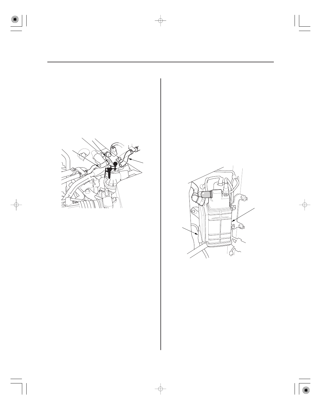
17. Reconnect the vacuum hose (engine side) (A) to the
EVAP canister purge valve (B) and disconnect the
vacuum hose (EVAP canister side) (C) from the
EVAP canister purge valve, then connect a vacuum
pump/gauge 0
30 in.Hg, to the vacuum hose as
shown.
18. Turn the ignition switch to ON (II).
19. Apply vacuum to the hose until the FTP reads
1.90 V (
15.1 mmHg,
0.59 in.Hg).
NOTE: Be careful not to exceed the vacuum. If you
do, the FTP sensor can be damaged.
20. Monitor the FTP SENSOR in the DATA LIST for
1 minute with the HDS.
Go to step 21.
Replace the EVAP canister purge valve
(see page 11-409), then go to step 29.
21. Check for a loose or damaged EVAP canister purge
line between the EVAP canister and the EVAP
canister purge valve or a leaking the EVAP canister.
Replace these parts, then go to step 29:
• FTP sensor O-ring
• EVAP canister vent shut valve case and O-ring
• EVAP canister
Reconnect or repair the EVAP canister purge
line, then go to step 29.
22. Reconnect the fresh air hose (A) to the EVAP
canister (B).
*: This illustration shows K20Z2 engine.
Does the voltage incr ease mor e than 0.2 V
( 2.5 mmHg, 0.1 in.Hg)?
Ar e the line and the EV AP canister OK ?
08/08/21 14:32:37 61SNR030_110_0388