Acura CSX. Manual - part 137


  Index      Acura     Acura CSX - P/NO. 61SNR03 - service repair manual 2006-2009 year


Search            


Content   ..  135  136  137  138   ..


Acura CSX. Manual - part 137


01

SNR9A00A20326916081KBAT20

01

SNR9A00A20326917523KBAT01

11-222

11-222

PGM-FI System

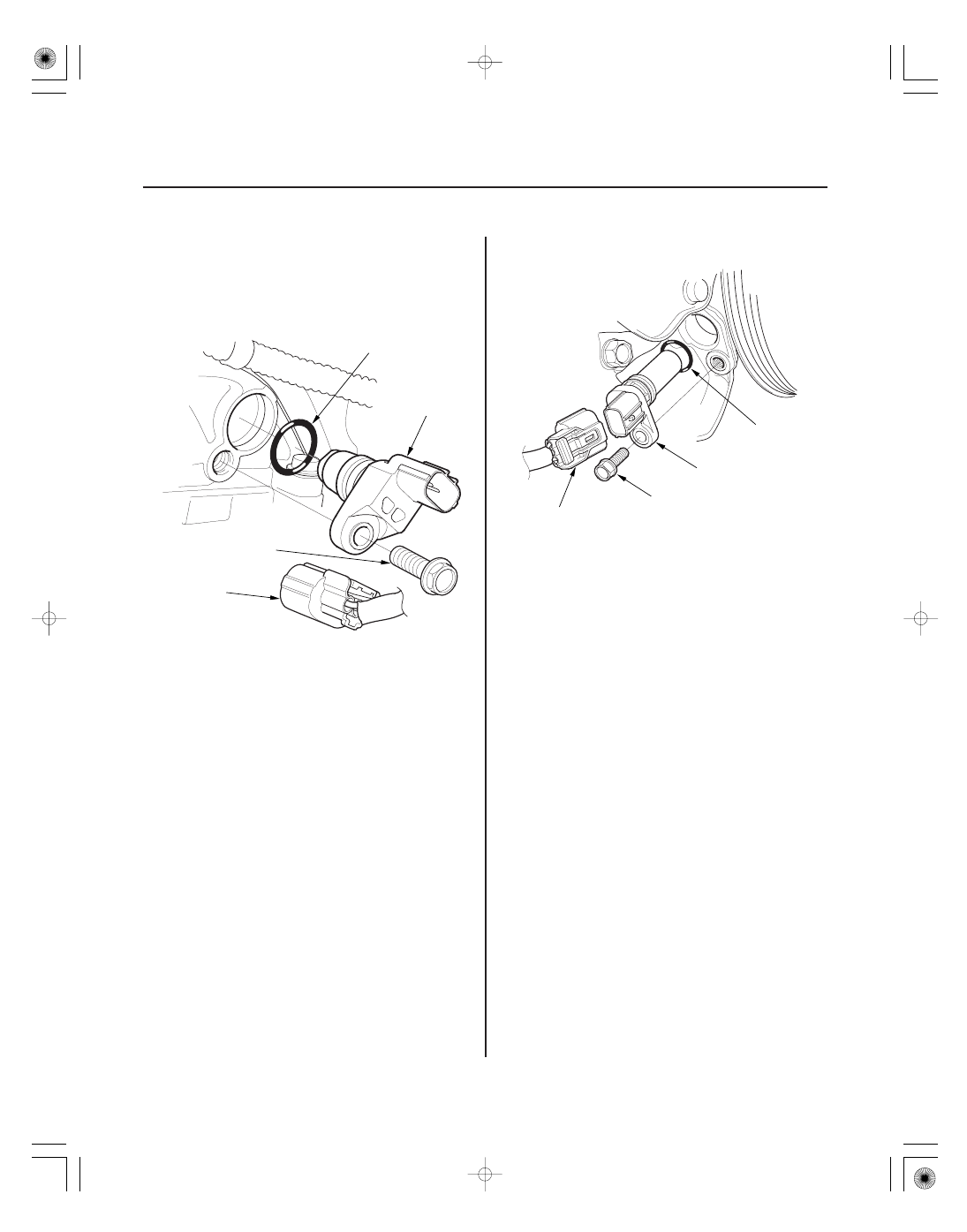
CMP Sensor B Replacement

CKP Sensor Replacement

C

B

A

12 N·m
(1.2 kgf·m,
8.7 lbf·ft)

12 N·m
(1.2 kgf·m, 8.7 lbf·ft)

A

B

C

1. Remove the air cleaner (see page 11-345).

2. K20Z2 engine: Remove the EGR valve (see page

11-370).

3. Disconnect the CMP sensor B 3P connector (A).

4. Remove CMP sensor B.

5. Install the parts in the reverse order of removal

with a new O-ring (C).

1. Disconnect the CKP sensor 3P connector (A).

2. Remove the CKP sensor (B).

3. Install the parts in the reverse order of removal

with a new O-ring (C).

4. Do the CKP pattern clear/CKP pattern learn

procedure with the HDS (see page 11-4).

08/08/21 14:23:36 61SNR030_110_0222

01

SNR9AA7A20326943821KBAT02

01

SNR9A00A20326936301KBAT20

M/T model

11-223

11-223

Output Shaft (Countershaft) Speed
Sensor Replacement

Knock Sensor Replacement

12 N·m
(1.2 kgf·m, 8.7 lbf·ft)

A

B

C

A

B
31 N·m (3.2 kgf·m, 23 lbf·ft)

NOTE: For A/T model (see page 14-227).

1. Disconnect the output shaft (countershaft) speed

sensor 3P connector (A).

2. Remove the output shaft (countershaft) speed

sensor (B).

3. Install the parts in the reverse order of removal

with a new O-ring (C).

1. Disconnect the knock sensor 1P connector (A).

2. Remove the knock sensor (B).

3. Install the parts in the reverse order of removal.

08/08/21 14:23:37 61SNR030_110_0223

01

SNR9A00A20326940001KBAT00

01

SNR9A00A20326940051KBAT02

11-224

11-224

PGM-FI System

MAP Sensor Replacement

MAF Sensor/IAT Sensor
Replacement

A

B

C

3.4 N·m
(0.34 kgf·m, 2.4 lbf·ft)

A

C

D

B
1.5 N·m
(0.15 kgf·m, 1.1 lbf·ft)

1. Disconnect the MAP sensor 3P connector (A).

2. Remove the MAP sensor (B).

3. Install the parts in the reverse order of removal

with a new O-ring (C).

1. Disconnect the MAF sensor/IAT sensor 5P

connector (A).

2. Remove the screws (B).

3. Remove the MAF sensor/IAT sensor (C).

4. Install the parts in the reverse order of removal

with a new O-ring (D).

* : This illustration shows K20Z2 engine

08/08/21 14:23:37 61SNR030_110_0224

01

02

SNR9A00A20326924711KBAT01

03

SNR9A00A20326924711KBAT02

11-225

11-225

ECT Sensor 1 Replacement

ECT Sensor 2 Replacement

A

B

C

B
12 N·m (1.2 kgf·m, 8.7 lbf·ft)

C

A

B
12 N·m
(1.2 kgf·m, 8.7 lbf·ft)

A

C

1. Drain the engine coolant (see page 10-8).

2. Remove the air cleaner (see page 11-345).

3. K20Z2 engine: Remove the EGR valve (see page

11-370).

4. Disconnect CMP sensor A 3P connector (A), and

CMP sensor B 3P connector.

5. Remove the harness cover (C).

6. Disconnect the ECT sensor 1 2P connector (A).

7. Remove ECT sensor 1 (B).

8. Install the parts in the reverse order of removal

with a new O-ring (C), then refill the radiator with
engine coolant (see page 10-8).

1. Drain the engine coolant (see page 10-8).

2. Remove the splash shield.

3. Disconnect the ECT sensor 2 2P connector (A), then

remove ECT sensor 2 (B).

4. Install the parts in the reverse order of removal

with a new O-ring (C).

5. Install the splash shield.

6. Refill the radiator with engine coolant (see page

10-8).

08/08/21 14:23:38 61SNR030_110_0225


Content   ..  135  136  137  138   ..