Acura CSX. Manual - part 81
*06
*07
−
−
−
−
YES
NO
YES
NO
10-28
Fan Controls
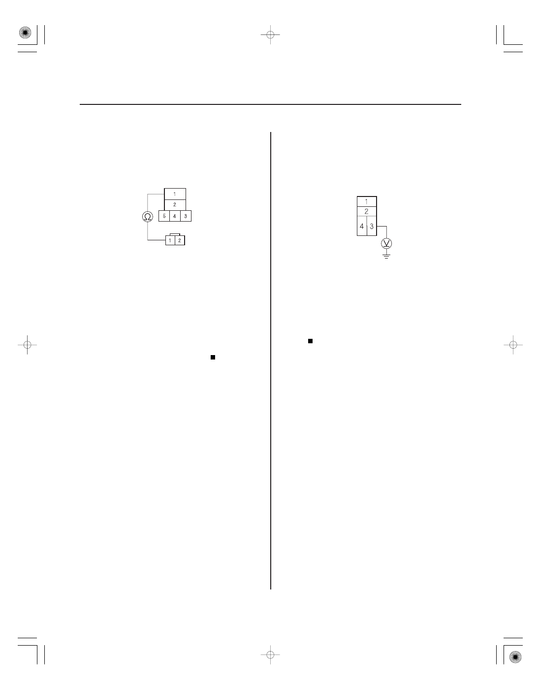
FAN CONTROL RELAY 5P SOCKET
RADIATOR FAN MOTOR 2P CONNECTOR
RED
RADIATOR FAN RELAY 4P SOCKET
9. Check for continuity between fan control relay 5P
socket terminal No. 1 and radiator fan motor 2P
connector terminal No. 1.
Check for poor connections or loose
terminals at the under-hood fuse/relay box, the
radiator fan motor, and body ground (G301), then
go to step 1.
Repair open in the wire between fan control
relay 5P socket terminal No. 1 and radiator fan
motor 2P connector terminal No. 1.
10. Turn the ignition switch to ON (II).
11. Measure the voltage between radiator fan relay 4P
socket terminal No. 3 and body ground.
Go to step 12.
Repair open in the wire between the under-
dash fuse/relay box and the under-hood fuse/relay
box.
12. Turn the ignition switch to LOCK (0).
13. Connect the Honda Diagnostic System (HDS) to the
data link connector (DLC) (see step 2 on page 11-3).
14. Turn the ignition switch to ON (II).
15. Make sure the HDS communicates with the vehicle
and the ECM/PCM. If it does not communicate,
troubleshoot the DLC circuit (see page 11-204).
16. Jump the SCS line with the HDS, then turn the
ignition switch to LOCK (0).
NOTE: This step must be done to protect the ECM/
PCM from damage.
17. Disconnect ECM/PCM connector A (44P).
Terminal side of female termianls
Wire side of female terminals
Terminal side of female terminals
Is ther e continuity?
Is ther e batter y voltage?
08/08/21 14:40:33 61SNR030_100_0028