Acura CSX. Manual - part 52


  Index      Acura     Acura CSX - P/NO. 61SNR03 - service repair manual 2006-2009 year


Search            


Content   ..  50  51  52  53   ..


Acura CSX. Manual - part 52


04

*01

SNR9A00A14680200000KCAT00

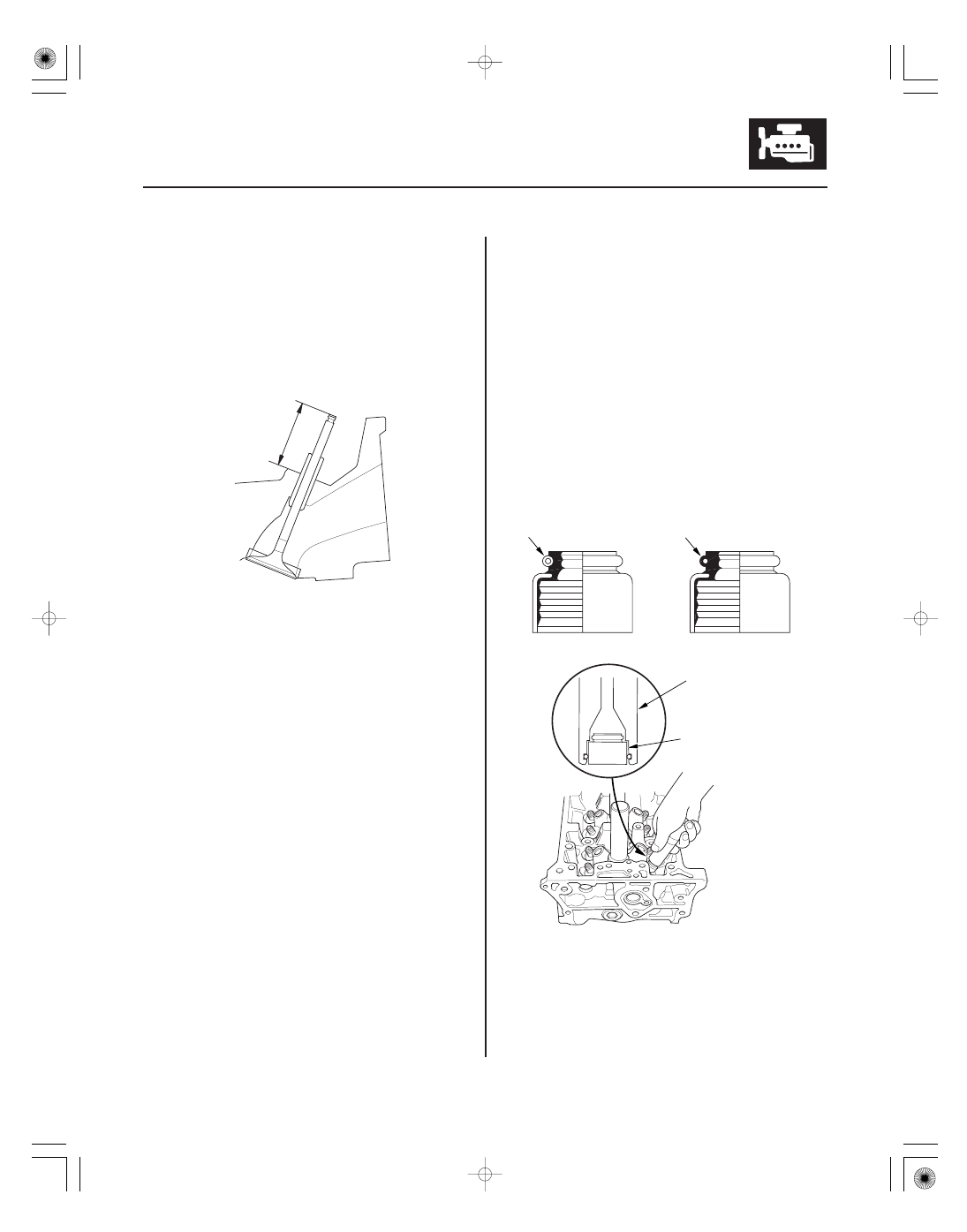
Intake Valve Stem Installed Height
Standard (New): 44.0

44.5 mm (1.73

1.75 in.)

Service Limit:

44.7 mm (1.76 in.)

Exhaust Valve Stem Installed Height
Standard (New): 44.1

44.6 mm (1.74

1.76 in.)

Service Limit:

44.8 mm (1.76 in.)

Special Tools Required

6-59

6-59

Valve, Spring, and Valve Seal
Installation

A

A

B
07PAD-0010000

F

D

E

C

8. Insert the intake and exhaust valves in the head,

and measure the valve stem installed height (A).

9. If the valve stem installed height is beyond the

service limit, replace the valve and recheck. If it is
still beyond the service limit, replace the cylinder
head, the valve seat in the head is too deep.

• Stem seal driver 07PAD-0010000
• Valve spring compressor attachment 07757-PJ1010A

1. Coat the valve stems with new engine oil. Install

the valves in the valve guides.

2. Check that the valves move up and down smoothly.

3. Install the spring seats on the cylinder head.

4. Install the new valve seals (A) using the 5.5 mm

side of the stem seal driver (B).

NOTE: The exhaust valve seal (C) has a black spring
(D), and the intake valve seal (E) has a white spring
(F). They are not interchangeable.

02

03

01

02

SNR9AEAA14666300000KCAT00

K20Z2 engine

6-60

6-60

Cylinder Head

Rocker Arm Assembly Installation

07757-PJ1010A

A

A

A

B

5. Install the valve spring and the spring retainer.

Place the end of the valve spring with the closely
wound coils toward the cylinder head.

6. Install the valve spring compressor attachment and

the valve spring compressor. Compress the valve
spring, and install the valve cotters.

7. Remove the valve spring compressor and the valve

spring compressor attachment.

8. Lightly tap the end of each valve stem two or three

times with a plastic mallet (A) to ensure proper
seating of the valve and valve keepers. Tap the
valve stem only along its axis so you do not bend
the stem.

1. Reassemble the rocker arm assembly (see page

6-46).

2. Clean and dry the No. 5 rocker shaft holder mating

surface.

3. Apply liquid gasket, P/N 08717-0004, 08718-0001,

08718-0003, or 08718-0009, evenly to the cylinder
head mating surface of the No. 5 rocker shaft
holder. Install the component within 5 minutes of
applying the liquid gasket.

NOTE:

• If you apply liquid gasket P/N 08718-0012, the

component must be install within 4 minutes.

• If too much time has passed after applying the

liquid gasket, remove the old liquid gasket and
residue, then reapply new liquid gasket.

4. Insert the bolts (A) into the rocker shaft holder, then

install the rocker arm assembly (B) on the cylinder
head.

Apply liquid gasket
along the broken line.

02

03

01

02

SNR9AEAA14666300000KCAT00

K20Z2 engine

6-60

6-60

Cylinder Head

Rocker Arm Assembly Installation

07757-PJ1010A

A

A

A

B

5. Install the valve spring and the spring retainer.

Place the end of the valve spring with the closely
wound coils toward the cylinder head.

6. Install the valve spring compressor attachment and

the valve spring compressor. Compress the valve
spring, and install the valve cotters.

7. Remove the valve spring compressor and the valve

spring compressor attachment.

8. Lightly tap the end of each valve stem two or three

times with a plastic mallet (A) to ensure proper
seating of the valve and valve keepers. Tap the
valve stem only along its axis so you do not bend
the stem.

1. Reassemble the rocker arm assembly (see page

6-46).

2. Clean and dry the No. 5 rocker shaft holder mating

surface.

3. Apply liquid gasket, P/N 08717-0004, 08718-0001,

08718-0003, or 08718-0009, evenly to the cylinder
head mating surface of the No. 5 rocker shaft
holder. Install the component within 5 minutes of
applying the liquid gasket.

NOTE:

• If you apply liquid gasket P/N 08718-0012, the

component must be install within 4 minutes.

• If too much time has passed after applying the

liquid gasket, remove the old liquid gasket and
residue, then reapply new liquid gasket.

4. Insert the bolts (A) into the rocker shaft holder, then

install the rocker arm assembly (B) on the cylinder
head.

Apply liquid gasket
along the broken line.

*01

04

01

02

SNR9AEBA14666300000KCAT01

Specified Torque
8 x 1.25 mm
22 N·m (2.2 kgf·m, 16 lbf·ft)
6 x 1.0 mm
12 N·m (1.2 kgf·m, 8.7 lbf·ft)
6 x 1.0 mm Bolts:

,

,

K20Z3 engine

6-61

6-61

C

A

B

A

A

B

5. Remove the bolts from the rocker shaft holder.

6. Make sure the punch marks on the variable valve

timing control (VTC) actuator and the exhaust
camshaft sprocket are facing up, then set the
camshafts (A) in the holder. Apply new engine oil to
the camshaft journals and lobes.

7. Set the camshaft holders (C) and cam chain guide B

in place.

8. Tighten the bolts to the specified torque.

9. Install the cam chain (see page 6-21), then adjust

the valve clearance (see page 6-12).

1. Reassemble the rocker arm assembly (see page

6-47).

2. Clean and dry the No. 5 rocker shaft holder mating

surface.

3. Apply liquid gasket, P/N 08717-0004, 08718-0001,

08718-0003, or 08718-0009, evenly to the cylinder
head mating surface of the No. 5 rocker shaft
holder. Install the component within 5 minutes of
applying the liquid gasket.

NOTE:

• If you apply liquid gasket P/N 08718-0012, the

component must be install within 4 minutes.

• If too much time has passed after applying the

liquid gasket, remove the old liquid gasket and
residue, then reapply new liquid gasket.

4. Insert the bolts (A) into the rocker shaft holder, then

install the rocker arm assembly (B) on the cylinder
head.

5. Remove the bolts from the rocker shaft holder.

Apply liquid gasket
along the broken line.


Content   ..  50  51  52  53   ..