Intel 64 and IA-32 Architectures. Software Developer’s Manual (Collection, 2023) - page 118

INTEL® PROCESSOR TRACE
Table 33-6. IA32_RTIT_CTL MSR (Contd.)
Position
Bit Name
At Reset
Bit Description
22:19
CycThresh
0
CYC packet threshold, see Section 33.3.6 for details. CYC packets will be sent with the first
eligible packet after N cycles have passed since the last CYC packet. If CycThresh is 0 then
N=0, otherwise N is defined as 2(CycThresh-1). The following Encodings are defined:
0: 0, 1: 1,
2: 2,
3: 4,
4: 8,
5: 16,
6: 32,
7: 64,
8: 128, 9: 256,
10: 512,
11: 1024,
12: 2048,
13: 4096,
14: 8192,
15: 16384
Software must use CPUID to query the supported encodings in the processor, see Section
33.3.1. Use of unsupported encodings will result in a #GP fault. This field is reserved if
CPUID.(EAX=14H, ECX=0):EBX[bit 1] = 0.
23
Reserved
0
Must be 0.
27:24
PSBFreq
0
Indicates the frequency of PSB packets. PSB packet frequency is based on the number of Intel
PT packet bytes output, so this field allows the user to determine the increment of
IA32_IA32_RTIT_STATUS.PacketByteCnt that should cause a PSB to be generated. Note that
PSB insertion is not precise, but the average output bytes per PSB should approximate the
SW selected period. The following Encodings are defined:
0: 2K, 1: 4K,
2: 8K,
3: 16K,
4: 32K,
5: 64K,
6: 128K,
7: 256K,
8: 512K, 9: 1M,
10: 2M,
11: 4M,
12: 8M,
13: 16M,
14: 32M,
15: 64M
Software must use CPUID to query the supported encodings in the processor, see Section
33.3.1. Use of unsupported encodings will result in a #GP fault. This field is reserved if
CPUID.(EAX=14H, ECX=0):EBX[bit 1] = 0.
30:28
Reserved
0
Must be 0.
31
EventEn
0
0: Event Trace packets are disabled.
1: Event Trace packets are enabled.
This bit is reserved when CPUID.(EAX=14H, ECX=0):EBX[bit 7] (“Event Trace Supported”) is 0.
35:32
ADDR0_CFG
0
Configures the base/limit register pair IA32_RTIT_ADDR0_A/B based on the following
encodings:
0: ADDR0 range unused.
1: The [IA32_RTIT_ADDR0_A..IA32_RTIT_ADDR0_B] range defines a FilterEn range. FilterEn
will only be set when the IP is within this range, though other FilterEn ranges can additionally
be used. See Section 33.2.5.3 for details on IP filtering.
2: The [IA32_RTIT_ADDR0_A..IA32_RTIT_ADDR0_B] range defines a TraceStop range.
TraceStop will be asserted if code branches into this range. See 4.2.8 for details on TraceStop.
3..15: Reserved (#GP).
This field is reserved if CPUID.(EAX=14H, ECX=1):EBX.RANGECNT[2:0] < 1.
39:36
ADDR1_CFG
0
Configures the base/limit register pair IA32_RTIT_ADDR1_A/B based on the following
encodings:
0: ADDR1 range unused.
1: The [IA32_RTIT_ADDR1_A..IA32_RTIT_ADDR1_B] range defines a FilterEn range. FilterEn
will only be set when the IP is within this range, though other FilterEn ranges can additionally
be used. See Section 33.2.5.3 for details on IP filtering.
2: The [IA32_RTIT_ADDR1_A..IA32_RTIT_ADDR1_B] range defines a TraceStop range.
TraceStop will be asserted if code branches into this range. See Section 33.4.2.10 for details
on TraceStop.
3..15: Reserved (#GP).
This field is reserved if CPUID.(EAX=14H, ECX=1):EBX.RANGECNT[2:0] < 2.
Vol. 3C
33-19

INTEL® PROCESSOR TRACE
Table 33-6. IA32_RTIT_CTL MSR (Contd.)
Position
Bit Name
At Reset
Bit Description
43:40
ADDR2_CFG
0
Configures the base/limit register pair IA32_RTIT_ADDR2_A/B based on the following
encodings:
0: ADDR2 range unused.
1: The [IA32_RTIT_ADDR2_A..IA32_RTIT_ADDR2_B] range defines a FilterEn range. FilterEn
will only be set when the IP is within this range, though other FilterEn ranges can additionally
be used. See Section 33.2.5.3 for details on IP filtering.
2: The [IA32_RTIT_ADDR2_A..IA32_RTIT_ADDR2_B] range defines a TraceStop range.
TraceStop will be asserted if code branches into this range. See Section 33.4.2.10 for details
on TraceStop.
3..15: Reserved (#GP).
This field is reserved if CPUID.(EAX=14H, ECX=1):EBX.RANGECNT[2:0] < 3.
47:44
ADDR3_CFG
0
Configures the base/limit register pair IA32_RTIT_ADDR3_A/B based on the following
encodings:
0: ADDR3 range unused.
1: The [IA32_RTIT_ADDR3_A..IA32_RTIT_ADDR3_B] range defines a FilterEn range. FilterEn
will only be set when the IP is within this range, though other FilterEn ranges can additionally
be used. See Section 33.2.5.3 for details on IP filtering.
2: The [IA32_RTIT_ADDR3_A..IA32_RTIT_ADDR3_B] range defines a TraceStop range.
TraceStop will be asserted if code branches into this range. See Section 33.4.2.10 for details
on TraceStop.
3..15: Reserved (#GP).
This field is reserved if CPUID.(EAX=14H, ECX=1):EBX.RANGECNT[2:0] < 4.
54:48
Reserved
0
Reserved only for future trace content enables, or address filtering configuration enables.
Must be 0.
55
DisTNT
0
0: Include TNT packets in control flow trace.
1: Omit TNT packets from control flow trace.
This bit is reserved when CPUID.(EAX=14H, ECX=0):EBX[bit 8] (“TNT Disable Supported”) is 0.
SeeSection 33.3.9 for details.
56
InjectPsbPmi
0
1: Enables use of IA32_RTIT_STATUS bits PendPSB[6] and PendTopaPMI[7], see Section
OnEnable
33.2.8.4, “IA32_RTIT_STATUS MSR,” for behavior of these bits.
0: IA32_RTIT_STATUS bits 6 and 7 are ignored.
This field is reserved if CPUID.(EAX=14H, ECX=0):EBX[bit 6] = 0.
59:57
Reserved
0
Reserved only for future trace content enables, or address filtering configuration enables.
Must be 0.
63:60
Reserved
0
Must be 0.
33.2.8.3 Enabling and Disabling Packet Generation with TraceEn
When TraceEn transitions from 0 to 1, Intel Processor Trace is enabled, and a series of packets may be generated.
These packets help ensure that the decoder is aware of the state of the processor when the trace begins, and that
it can keep track of any timing or state changes that may have occurred while packet generation was disabled. A
full PSB+ (see Section 33.4.2.17) will be generated if IA32_RTIT_STATUS.PacketByteCnt=0, and may be gener-
ated in other cases as well. Otherwise, timing packets will be generated, including TSC, TMA, and CBR (see Section
33.4.1.1).
In addition to the packets discussed above, if and when PacketEn (Section 33.2.6.1) transitions from 0 to 1 (which
may happen immediately, depending on filtering settings), a TIP.PGE packet (Section 33.4.2.3) will be generated.
When TraceEn is set, the processor may read ToPA entries from memory and cache them internally. For this reason,
software should disable packet generation before making modifications to the ToPA tables (or changing the config-
33-20
Vol. 3C

INTEL® PROCESSOR TRACE
uration of restricted memory regions). See Section 33.7 for more details of packets that may be generated with
modifications to TraceEn.
Disabling Packet Generation
Clearing TraceEn causes any packet data buffered within the logical processor to be flushed out, after which the
output MSRs (IA32_RTIT_OUTPUT_BASE and IA32_RTIT_OUTPUT_MASK_PTRS) will have stable values. When
output is directed to memory, a store, fence, or architecturally serializing instruction may be required to ensure
that the packet data is globally observed. No special packets are generated by disabling packet generation, though
a TIP.PGD may result if PacketEn=1 at the time of disable.
Other Writes to IA32_RTIT_CTL
Any attempt to modify IA32_RTIT_CTL while TraceEn is set will result in a general-protection fault (#GP) unless the
same write also clears TraceEn. However, writes to IA32_RTIT_CTL that do not modify any bits will not cause a
#GP, even if TraceEn remains set.
33.2.8.4 IA32_RTIT_STATUS MSR
The IA32_RTIT_STATUS MSR is readable and writable by software, though some fields cannot be modified by soft-
ware. See Table 33-7 for details. The WRMSR instruction ignores these bits in the source operand (attempts to
modify these bits are ignored and do not cause WRMSR to fault).
This MSR can only be written when IA32_RTIT_CTL.TraceEn is 0; otherwise WRMSR causes a general-protection
fault (#GP). The processor does not modify the value of this MSR while TraceEn is 0 (software can modify it with
WRMSR).
Table 33-7. IA32_RTIT_STATUS MSR
Position
Bit Name
At Reset
Bit Description
0
FilterEn
0
This bit is written by the processor, and indicates that tracing is allowed for the current IP,
see Section 33.2.6.5. Writes are ignored.
1
ContextEn
0
The processor sets this bit to indicate that tracing is allowed for the current context. See
Section 33.2.6.3. Writes are ignored.
2
TriggerEn
0
The processor sets this bit to indicate that tracing is enabled. See Section 33.2.6.2. Writes are
ignored.
3
Reserved
0
Must be 0.
4
Error
0
The processor sets this bit to indicate that an operational error has been encountered. When
this bit is set, TriggerEn is cleared to 0 and packet generation is disabled. For details, see
“ToPA Errors” in Section 33.2.7.2.
When TraceEn is cleared, software can write this bit. Once it is set, only software can clear it.
It is not recommended that software ever set this bit, except in cases where it is restoring a
prior saved state.
5
Stopped
0
The processor sets this bit to indicate that a ToPA Stop condition has been encountered.
When this bit is set, TriggerEn is cleared to 0 and packet generation is disabled. For details,
see “ToPA STOP” in Section 33.2.7.2.
When TraceEn is cleared, software can write this bit. Once it is set, only software can clear it.
It is not recommended that software ever set this bit, except in cases where it is restoring a
prior saved state.
6
PendPSB
0
If IA32_RTIT_CTL.InjectPsbPmiOnEnable[56] = 1, the processor sets this bit when the
threshold for a PSB+ to be inserted has been reached. The processor will clear this bit when
the PSB+ has been inserted into the trace. If PendPSB = 1 and InjectPsbPmiOnEnable = 1
when IA32_RTIT_CTL.TraceEn[0] transitions from 0 to 1, a PSB+ will be inserted into the
trace.
This field is reserved if CPUID.(EAX=14H, ECX=0):EBX[bit 6] = 0.
Vol. 3C
33-21

INTEL® PROCESSOR TRACE
Table 33-7. IA32_RTIT_STATUS MSR
Position
Bit Name
At Reset
Bit Description
7
PendTopaPMI
0
If IA32_RTIT_CTL.InjectPsbPmiOnEnable[56] = 1, the processor sets this bit when the
threshold for a ToPA PMI to be inserted has been reached. Software should clear this bit once
the ToPA PMI has been handled, see “ToPA PMI” for details. If PendTopaPMI = 1 and
InjectPsbPmiOnEnable = 1 when IA32_RTIT_CTL.TraceEn[0] transitions from 0 to 1, a PMI will
be pended.
This field is reserved if CPUID.(EAX=14H, ECX=0):EBX[bit 6] = 0.
31:8
Reserved
0
Must be 0.
48:32
PacketByteCnt
0
This field is written by the processor, and holds a count of packet bytes that have been sent
out. The processor also uses this field to determine when the next PSB packet should be
inserted. Note that the processor may clear or modify this field at any time while
IA32_RTIT_CTL.TraceEn=1. It will have a stable value when IA32_RTIT_CTL.TraceEn=0.
See Section 33.4.2.17 for details.
This field is reserved when CPUID.(EAX=14H,ECX=0):EBX[bit 1] (“Configurable PSB and
CycleAccurate Mode Supported”) is 0.
63:49
Reserved
0
Must be 0.
33.2.8.5 IA32_RTIT_ADDRn_A and IA32_RTIT_ADDRn_B MSRs
The role of the IA32_RTIT_ADDRn_A/B register pairs, for each n, is determined by the corresponding ADDRn_CFG
fields in IA32_RTIT_CTL (see Section 33.2.8.2). The number of these register pairs is enumerated by
CPUID.(EAX=14H, ECX=1):EAX.RANGECNT[2:0].
• Processors that enumerate support for 1 range support:
— IA32_RTIT_ADDR0_A, IA32_RTIT_ADDR0_B
• Processors that enumerate support for 2 ranges support:
— IA32_RTIT_ADDR0_A, IA32_RTIT_ADDR0_B
— IA32_RTIT_ADDR1_A, IA32_RTIT_ADDR1_B
• Processors that enumerate support for 3 ranges support:
— IA32_RTIT_ADDR0_A, IA32_RTIT_ADDR0_B
— IA32_RTIT_ADDR1_A, IA32_RTIT_ADDR1_B
— IA32_RTIT_ADDR2_A, IA32_RTIT_ADDR2_B
• Processors that enumerate support for 4 ranges support:
— IA32_RTIT_ADDR0_A, IA32_RTIT_ADDR0_B
— IA32_RTIT_ADDR1_A, IA32_RTIT_ADDR1_B
— IA32_RTIT_ADDR2_A, IA32_RTIT_ADDR2_B
— IA32_RTIT_ADDR3_A, IA32_RTIT_ADDR3_B
Each register has a single 64-bit field that holds a linear address value. Writes must ensure that the address is in
canonical form, otherwise a general-protection fault (#GP) fault will result.
Each MSR can be written only when IA32_RTIT_CTL.TraceEn is 0; otherwise WRMSR causes a general-protection
fault (#GP).
33.2.8.6 IA32_RTIT_CR3_MATCH MSR
The IA32_RTIT_CR3_MATCH register is compared against CR3 when IA32_RTIT_CTL.CR3Filter is 1. Bits 63:5 hold
the CR3 address value to match, bits 4:0 are reserved to 0. For more details on CR3 filtering and the treatment of
this register, see Section 33.2.5.2.
33-22
Vol. 3C

INTEL® PROCESSOR TRACE
This MSR is accessible if CPUID.(EAX=14H, ECX=0):EBX[bit 0], “CR3 Filtering Support”, is 1. This MSR can be
written only when IA32_RTIT_CTL.TraceEn is 0; otherwise WRMSR causes a general-protection fault (#GP).
IA32_RTIT_CR3_MATCH[4:0] are reserved and must be 0; an attempt to set those bits using WRMSR causes a
#GP.
33.2.8.7 IA32_RTIT_OUTPUT_BASE MSR
This MSR is used to configure the trace output destination, when output is directed to memory
(IA32_RTIT_CTL.FabricEn = 0). The size of the address field is determined by the maximum physical address width
(MAXPHYADDR), as reported by CPUID.80000008H:EAX[7:0].
When the ToPA output scheme is used, the processor may update this MSR when packet generation is enabled, and
those updates are asynchronous to instruction execution. Therefore, the values in this MSR should be considered
unreliable unless packet generation is disabled (IA32_RTIT_CTL.TraceEn = 0).
Accesses to this MSR are supported only if Intel PT output to memory is supported, hence when either
CPUID.(EAX=14H, ECX=0):ECX[bit 0] or CPUID.(EAX=14H, ECX=0):ECX[bit 2] are set. Otherwise WRMSR or
RDMSR cause a general-protection fault (#GP). If supported, this MSR can be written only when
IA32_RTIT_CTL.TraceEn is 0; otherwise WRMSR causes a general-protection fault (#GP).
Table 33-8. IA32_RTIT_OUTPUT_BASE MSR
Position
Bit Name
At Reset
Bit Description
6:0
Reserved
0
Must be 0.
MAXPHYADDR-1:7
BasePhysAddr
0
The base physical address. How this address is used depends on the value of
IA32_RTIT_CTL.ToPA:
0: This is the base physical address of a single, contiguous physical output region.
This could be mapped to DRAM or to MMIO, depending on the value.
The base address should be aligned with the size of the region, such that none of
the 1s in the mask value(Section 33.2.8.8) overlap with 1s in the base address. If
the base is not aligned, an operational error will result (see Section 33.3.10).
1: The base physical address of the current ToPA table. The address must be 4K
aligned. Writing an address in which bits 11:7 are non-zero will not cause a #GP, but
an operational error will be signaled once TraceEn is set. See “ToPA Errors” in
Section 33.2.7.2, as well as Section 33.3.10.
63:MAXPHYADDR
Reserved
0
Must be 0.
33.2.8.8 IA32_RTIT_OUTPUT_MASK_PTRS MSR
This MSR holds any mask or pointer values needed to indicate where the next byte of trace output should be
written. The meaning of the values held in this MSR depend on whether the ToPA output mechanism is in use. See
Section 33.2.7.2 for details.
The processor updates this MSR while when packet generation is enabled, and those updates are asynchronous to
instruction execution. Therefore, the values in this MSR should be considered unreliable unless packet generation
is disabled (IA32_RTIT_CTL.TraceEn = 0).
Accesses to this MSR are supported only if Intel PT output to memory is supported, hence when either
CPUID.(EAX=14H, ECX=0):ECX[bit 0] or CPUID.(EAX=14H, ECX=0):ECX[bit 2] are set. Otherwise WRMSR or
RDMSR cause a general-protection fault (#GP). If supported, this MSR can be written only when
IA32_RTIT_CTL.TraceEn is 0; otherwise WRMSR causes a general-protection fault (#GP).
Vol. 3C
33-23

INTEL® PROCESSOR TRACE
Table 33-9. IA32_RTIT_OUTPUT_MASK_PTRS MSR
Position
Bit Name
At Reset
Bit Description
6:0
LowerMask
7FH
Forced to 1, writes are ignored.
31:7
MaskOrTableO
0
The use of this field depends on the value of IA32_RTIT_CTL.ToPA:
ffset
0: This field holds bits 31:7 of the mask value for the single, contiguous physical output
region. The size of this field indicates that regions can be of size 128B up to 4GB. This value
(combined with the lower 7 bits, which are reserved to 1) will be ANDed with the
OutputOffset field to determine the next write address. All 1s in this field should be
consecutive and starting at bit 7, otherwise the region will not be contiguous, and an
operational error (Section 33.3.10) will be signaled when TraceEn is set.
1: This field holds bits 27:3 of the offset pointer into the current ToPA table. This value can
be added to the IA32_RTIT_OUTPUT_BASE value to produce a pointer to the current ToPA
table entry, which itself is a pointer to the current output region. In this scenario, the lower 7
reserved bits are ignored. This field supports tables up to 256 MBytes in size.
63:32
OutputOffset
0
The use of this field depends on the value of IA32_RTIT_CTL.ToPA:
0: This is bits 31:0 of the offset pointer into the single, contiguous physical output region.
This value will be added to the IA32_RTIT_OUTPUT_BASE value to form the physical address
at which the next byte of packet output data will be written. This value must be less than or
equal to the MaskOrTableOffset field, otherwise an operational error (Section 33.3.10) will
be signaled when TraceEn is set.
1: This field holds bits 31:0 of the offset pointer into the current ToPA output region. This
value will be added to the output region base field, found in the current ToPA table entry, to
form the physical address at which the next byte of trace output data will be written.
This value must be less than the ToPA entry size, otherwise an operational error (Section
33.3.10) will be signaled when TraceEn is set.
33.2.9 Interaction of Intel® Processor Trace and Other Processor Features
33.2.9.1 Intel® Transactional Synchronization Extensions (Intel® TSX)
The operation of Intel TSX is described in Chapter 14 of the Intel® 64 and IA-32 Architectures Software Developer’s
Manual, Volume 1. For tracing purpose, packet generation does not distinguish between hardware lock elision
(HLE) and restricted transactional memory (RTM), but speculative execution does have impacts on the trace
output. Specifically, packets are generated as instructions complete, even for instructions in a transactional region
that is later aborted. For this reason, debugging software will need indication of the beginning and end of a trans-
actional region; this will allow software to understand when instructions are part of a transactional region and
whether that region has been committed.
To enable this, TSX information is included in a MODE packet leaf. The mode bits in the leaf are:
• InTX: Set to 1 on an TSX transaction begin, and cleared on transaction commit or abort.
• TXAbort: Set to 1 only when InTX transitions from 1 to 0 on an abort. Cleared otherwise.
If BranchEn=1, this MODE packet will be sent each time the transaction status changes. See Table 33-10 for
details.
Table 33-10. TSX Packet Scenarios with BranchEn=1
TSX Event
Instruction
Packets
Transaction Begin
Either XBEGIN or XACQUIRE lock (the latter if executed
MODE(TXAbort=0, InTX=1), FUP(CurrentIP)
transactionally)
Transaction
Either XEND or XRELEASE lock, if transactional execution
MODE(TXAbort=0, InTX=0), FUP(CurrentIP)
Commit
ends. This happens only on the outermost commit
33-24
Vol. 3C

INTEL® PROCESSOR TRACE
Table 33-10. TSX Packet Scenarios with BranchEn=1
TSX Event
Instruction
Packets
Transaction Abort
XABORT or other transactional abort
MODE(TXAbort=1, InTX=0), FUP(CurrentIP),
TIP(TargetIP)
Other
One of the following:
None. No change to TSX mode bits for these
• Nested XBEGIN or XACQUIRE lock
cases.
• An outer XACQUIRE lock that doesn’t begin a transaction
(InTX not set)
• Non-outermost XEND or XRELEASE lock
The CurrentIP listed above is the IP of the associated instruction. The TargetIP is the IP of the next instruction to
be executed; for HLE, this is the XACQUIRE lock; for RTM, this is the fallback handler.
Intel PT stores are non-transactional, and thus packet writes are not rolled back on TSX abort.
33.2.9.2 TSX and IP Filtering
A complication with tracking transactions is handling transactions that start or end outside of the tracing region.
Transactions can’t span across a change in ContextEn, because CPL changes and CR3 changes each cause aborts.
But a transaction can start within the IP filter region and end outside it.
To assist the decoder handling this situation, MODE.TSX packets can be sent even if FilterEn=0, though there will
be no FUP attached. Instead, they will merely serve to indicate to the decoder when transactions are active and
when they are not. When tracing resumes (due to PacketEn=1), the last MODE.TSX preceding the TIP.PGE will indi-
cate the current transaction status.
33.2.9.3 System Management Mode (SMM)
SMM code has special privileges that non-SMM code does not have. Intel Processor Trace can be used to trace SMM
code, but special care is taken to ensure that SMM handler context is not exposed in any non-SMM trace collection.
Additionally, packet output from tracing non-SMM code cannot be written into memory space that is either
protected by SMRR or used by the SMM handler.
SMM is entered via a system management interrupt (SMI). SMI delivery saves the value of
IA32_RTIT_CTL.TraceEn into SMRAM and then clears it, thereby disabling packet generation.
The saving and clearing of IA32_RTIT_CTL.TraceEn ensures two things:
1. All internally buffered packet data is flushed before entering SMM (see Section 33.2.8.2).
2. Packet generation ceases before entering SMM, so any tracing that was configured outside SMM does not
continue into SMM. No SMM instruction pointers or other state will be exposed in the non-SMM trace.
When the RSM instruction is executed to return from SMM, the TraceEn value that was saved by SMI delivery is
restored, allowing tracing to be resumed. As is done any time packet generation is enabled, ContextEn is re-eval-
uated, based on the values of CPL, CR3, etc., established by RSM.
Like other interrupts, delivery of an SMI produces a FUP containing the IP of the next instruction to execute. By
toggling TraceEn, SMI and RSM can produce TIP.PGD and TIP.PGE packets, respectively, indicating that tracing was
disabled or re-enabled. See Table 33.7 for more information about packets entering and leaving SMM.
Although #SMI and RSM change CR3, PIP packets are not generated in these cases. With #SMI tracing is disabled
before the CR3 change; with RSM TraceEn is restored after CR3 is written.
TraceEn must be cleared before executing RSM, otherwise it will cause a shutdown. Further, on processors that
restrict use of Intel PT with LBRs (see Section 33.3.1.2), any RSM that results in enabling of both will cause a shut-
down.
Intel PT can support tracing of System Transfer Monitor operating in SMM, see Section 33.6.
Vol. 3C
33-25
INTEL® PROCESSOR TRACE
33.2.9.4 Virtual-Machine Extensions (VMX)
Initial implementations of Intel Processor Trace do not support tracing in VMX operation. Such processors indicate
this by returning 0 for IA32_VMX_MISC[bit 14]. On these processors, execution of the VMXON instruction clears
IA32_RTIT_CTL.TraceEn and any attempt to write IA32_RTIT_CTL in VMX operation causes a general-protection
exception (#GP).
Processors that support Intel Processor Trace in VMX operation return 1 for IA32_VMX_MISC[bit 14]. Details of
tracing in VMX operation are described in Section 33.4.2.26.
33.2.9.5 Intel® Software Guard Extensions (Intel® SGX)
Intel SGX provides an application with the ability to instantiate a protective container (an enclave) with confidenti-
ality and integrity (see the Intel® 64 and IA-32 Architectures Software Developer’s Manual, Volume 3D). On a
processor with both Intel PT and Intel SGX enabled, when executing code within a production enclave, no control
flow packets are produced by Intel PT. An enclave entry will clear ContextEn, thereby blocking control flow packet
generation. A TIP.PGD packet will be generated if PacketEn=1 at the time of the entry.
Upon enclave exit, ContextEn will no longer be forced to 0. If other enables are set at the time, a TIP.PGE may be
generated to indicate that tracing is resumed.
During the enclave execution, Intel PT remains enabled, and periodic or timing packets such as PSB, TSC, MTC, or
CBR can still be generated. No IPs or other architectural state will be exposed.
For packet generation examples on enclave entry or exit, see Section 33.7.
Debug Enclaves
Intel SGX allows an enclave to be configured with relaxed protection of confidentiality for debug purposes, see the
Intel® 64 and IA-32 Architectures Software Developer’s Manual, Volume 3D. In a debug enclave, Intel PT continues
to function normally. Specifically, ContextEn is not impacted by an enclave entry or exit. Hence, the generation of
ContextEn-dependent packets within a debug enclave is allowed.
33.2.9.6 SENTER/ENTERACCS and ACM
GETSEC[SENTER] and GETSEC[ENTERACCS] instructions clear TraceEn, and it is not restored when those instruc-
tion complete. SENTER also causes TraceEn to be cleared on other logical processors when they rendezvous and
enter the SENTER sleep state. In these two cases, the disabling of packet generation is not guaranteed to flush
internally buffered packets. Some packets may be dropped.
When executing an authenticated code module (ACM), packet generation is silently disabled during ACRAM setup.
TraceEn will be cleared, but no TIP.PGD packet is generated. After completion of the module, the TraceEn value will
be restored. There will be no TIP.PGE packet, but timing packets, like TSC and CBR, may be produced.
33.2.9.7 Intel® Memory Protection Extensions (Intel® MPX)
Bounds exceptions (#BR) caused by Intel MPX are treated like other exceptions, producing FUP and TIP packets
that indicate the source and destination IPs.
33.3
CONFIGURATION AND PROGRAMMING GUIDELINE
33.3.1 Detection of Intel Processor Trace and Capability Enumeration
Processor support for Intel Processor Trace is indicated by CPUID.(EAX=07H,ECX=0H):EBX[bit 25] = 1. CPUID
function 14H is dedicated to enumerate the resource and capability of processors that report
CPUID.(EAX=07H,ECX=0H):EBX[bit 25] = 1. Different processor generations may have architecturally-defined
variation in capabilities. Table 33-11 describes details of the enumerable capabilities that software must use across
generations of processors that support Intel Processor Trace.
33-26
Vol. 3C

INTEL® PROCESSOR TRACE
Table 33-11. CPUID Leaf 14H Enumeration of Intel Processor Trace Capabilities
CPUID.(EAX=14H,ECX=0)
Name
Description Behavior
Register
Bits
EAX
31:0
Maximum valid sub-leaf Index
Specifies the index of the maximum valid sub-leaf for this CPUID leaf.
0
CR3 Filtering Support
1: Indicates that IA32_RTIT_CTL.CR3Filter can be set to 1, and that
IA32_RTIT_CR3_MATCH MSR can be accessed. See Section 33.2.8.
EBX
0: Indicates that writes that set IA32_RTIT_CTL.CR3Filter to 1, or any
access to IA32_RTIT_CR3_MATCH, will generate a #GP exception.
1
Configurable PSB and Cycle-
1: (a) IA32_RTIT_CTL.PSBFreq can be set to a non-zero value, in order to
Accurate Mode Supported
select the preferred PSB frequency (see below for allowed values). (b)
IA32_RTIT_STATUS.PacketByteCnt can be set to a non-zero value, and
will be incremented by the processor when tracing to indicate progress
towards the next PSB. If trace packet generation is enabled by setting
TraceEn, a PSB will only be generated if PacketByteCnt=0. (c)
IA32_RTIT_CTL.CYCEn can be set to 1 to enable Cycle-Accurate Mode.
See Section 33.2.8.
0: (a) Any attempt to write a non-zero value to IA32_RTIT_CTL.PSBFreq
or IA32_RTIT_STATUS.PacketByteCnt will generate a #GP exception. (b)
If trace packet generation is enabled by setting TraceEn, a PSB is always
generated. (c) Any attempt to write a non-zero value to
IA32_RTIT_CTL.CYCEn or IA32_RTIT_CTL.CycThresh will generate a #GP
exception.
2
IP Filtering and TraceStop
1: (a) IA32_RTIT_CTL provides at one or more ADDRn_CFG field to
supported, and Preserve Intel
configure the corresponding address range MSRs for IP Filtering or IP
PT MSRs across warm reset
TraceStop. Each ADDRn_CFG field accepts a value in the range of 0:2
inclusive. The number of ADDRn_CFG fields is reported by
CPUID.(EAX=14H, ECX=1):EAX.RANGECNT[2:0]. (b) At least one register
pair IA32_RTIT_ADDRn_A and IA32_RTIT_ADDRn_B are provided to
configure address ranges for IP filtering or IP TraceStop. (c) On warm
reset, all Intel PT MSRs will retain their pre-reset values, though
IA32_RTIT_CTL.TraceEn will be cleared. The Intel PT MSRs are listed in
Section 33.2.8.
0: (a) An Attempt to write IA32_RTIT_CTL.ADDRn_CFG with non-zero
encoding values will cause #GP. (b) Any access to IA32_RTIT_ADDRn_A
and IA32_RTIT_ADDRn_B, will generate a #GP exception. (c) On warm
reset, all Intel PT MSRs will be cleared.
3
MTC Supported
1: IA32_RTIT_CTL.MTCEn can be set to 1, and MTC packets will be
generated. See Section 33.2.8.
0: An attempt to set IA32_RTIT_CTL.MTCEn or IA32_RTIT_CTL.MTCFreq
to a non-zero value will generate a #GP exception.
4
PTWRITE Supported
1: Writes can set IA32_RTIT_CTL[12] (PTWEn) and IA32_RTIT_CTL[5]
(FUPonPTW), and PTWRITE can generate packets.
0: Writes that set IA32_RTIT_CTL[12] or IA32_RTIT_CTL[5] will
generate a #GP exception, and PTWRITE will #UD fault.
5
Power Event Trace Supported
1: Writes can set IA32_RTIT_CTL[4] (PwrEvtEn), enabling Power Event
Trace packet generation.
0: Writes that set IA32_RTIT_CTL[4] will generate a #GP exception.
Vol. 3C
33-27

INTEL® PROCESSOR TRACE
Table 33-11. CPUID Leaf 14H Enumeration of Intel Processor Trace Capabilities (Contd.)
CPUID.(EAX=14H,ECX=0)
Name
Description Behavior
Register
Bits
6
PSB and PMI Preservation
1: Writes can set IA32_RTIT_CTL[56] (InjectPsbPmiOnEnable), enabling
Supported
the processor to set IA32_RTIT_STATUS[7] (PendTopaPMI) and/or
IA32_RTIT_STATUS[6] (PendPSB) in order to preserve ToPA PMIs and/or
PSBs otherwise lost due to Intel PT disable. Writes can also set
PendToPAPMI and PendPSB.
0: Writes that set IA32_RTIT_CTL[56], IA32_RTIT_STATUS[7], or
IA32_RTIT_STATUS[6] will generate a #GP exception.
7
Event Trace Supported
1: Writes can set IA32_RTIT_CTL[31] (EventEn), enabling Event Trace
packet generation.
0: Writes that set IA32_RTIT_CTL[31] will generate a #GP exception.
8
TNT Disable Supported
1: Writes can set IA32_RTIT_CTL[55] (DisTNT), disabling TNT packet
generation.
0: Writes that set IA32_RTIT_CTL[55] will generate a #GP exception.
31:9
Reserved
0
ToPA Output Supported
1: Tracing can be enabled with IA32_RTIT_CTL.ToPA = 1, hence utilizing
the ToPA output scheme (Section 33.2.7.2) IA32_RTIT_OUTPUT_BASE
and IA32_RTIT_OUTPUT_MASK_PTRS MSRs can be accessed.
ECX
0: Unless CPUID.(EAX=14H, ECX=0):ECX.SNGLRNGOUT[bit 2] = 1. writes
to IA32_RTIT_OUTPUT_BASE or IA32_RTIT_OUTPUT_MASK_PTRS.
MSRs will generate a #GP exception.
1
ToPA Tables Allow Multiple
1: ToPA tables can hold any number of output entries, up to the
Output Entries
maximum allowed by the MaskOrTableOffset field of
IA32_RTIT_OUTPUT_MASK_PTRS.
0: ToPA tables can hold only one output entry, which must be followed
by an END=1 entry which points back to the base of the table.
Further, ToPA PMIs will be delivered before the region is filled. See ToPA
PMI in Section 33.2.7.2.
If there is more than one output entry before the END entry, or if the
END entry has the wrong base address, an operational error will be
signaled (see “ToPA Errors” in Section 33.2.7.2).
2
Single-Range Output
1: Enabling tracing (TraceEn=1) with IA32_RTIT_CTL.ToPA=0 is
Supported
supported.
0: Unless CPUID.(EAX=14H, ECX=0):ECX.TOPAOUT[bit 0] = 1. writes to
IA32_RTIT_OUTPUT_BASE or IA32_RTIT_OUTPUT_MASK_PTRS. MSRs
will generate a #GP exception.
3
Output to Trace Transport
1: Setting IA32_RTIT_CTL.FabricEn to 1 is supported.
Subsystem Supported
0: IA32_RTIT_CTL.FabricEn is reserved. Write 1 to
IA32_RTIT_CTL.FabricEn will generate a #GP exception.
30:4
Reserved
31
IP Payloads are LIP
1: Generated packets which contain IP payloads have LIP values, which
include the CS base component.
0: Generated packets which contain IP payloads have RIP values, which
are the offset from CS base.
EDX
31:0
Reserved
If CPUID.(EAX=14H, ECX=0):EAX reports a non-zero value, additional capabilities of Intel Processor Trace are
described in the sub-leaves of CPUID leaf 14H.
33-28
Vol. 3C

INTEL® PROCESSOR TRACE
Table 33-12. CPUID Leaf 14H, sub-leaf 1H Enumeration of Intel Processor Trace Capabilities
CPUID.(EAX=14H,ECX=1)
Name
Description Behavior
Register
Bits
EAX
2:0
Number of Address Ranges
A non-zero value specifies the number ADDRn_CFG field supported in
IA32_RTIT_CTL and the number of register pair
IA32_RTIT_ADDRn_A/IA32_RTIT_ADDRn_B supported for IP filtering
and IP TraceStop.
NOTE: Currently, no processors support more than 4 address ranges.
15:3
Reserved
31:16
Bitmap of supported MTC
The non-zero bits indicate the map of supported encoding values for
Period Encodings
the IA32_RTIT_CTL.MTCFreq field. This applies only if
CPUID.(EAX=14H, ECX=0):EBX[bit 3] = 1 (MTC Packet generation is
supported), otherwise the MTCFreq field is reserved to 0.
Each bit position in this field represents 1 encoding value in the 4-bit
MTCFreq field (ie, bit 0 is associated with encoding value 0). For each
bit:
1: MTCFreq can be assigned the associated encoding value.
0: MTCFreq cannot be assigned to the associated encoding value. A
write to IA32_RTIT_CTLMTCFreq with unsupported encoding will cause
#GP fault.
EBX
15:0
Bitmap of supported Cycle
The non-zero bits indicate the map of supported encoding values for
Threshold values
the IA32_RTIT_CTL.CycThresh field. This applies only if
CPUID.(EAX=14H, ECX=0):EBX[bit 1] = 1 (Cycle-Accurate Mode is
Supported), otherwise the CycThresh field is reserved to 0. See Section
33.2.8.
Each bit position in this field represents 1 encoding value in the 4-bit
CycThresh field (ie, bit 0 is associated with encoding value 0). For each
bit:
1: CycThresh can be assigned the associated encoding value.
0: CycThresh cannot be assigned to the associated encoding value. A
write to CycThresh with unsupported encoding will cause #GP fault.
31:16
Bitmap of supported
The non-zero bits indicate the map of supported encoding values for
Configurable PSB Frequency
the IA32_RTIT_CTL.PSBFreq field. This applies only if
encoding
CPUID.(EAX=14H, ECX=0):EBX[bit 1] = 1 (Configurable PSB is
supported), otherwise the PSBFreq field is reserved to 0. See Section
33.2.8.
Each bit position in this field represents 1 encoding value in the 4-bit
PSBFreq field (ie, bit 0 is associated with encoding value 0). For each
bit:
1: PSBFreq can be assigned the associated encoding value.
0: PSBFreq cannot be assigned to the associated encoding value. A
write to PSBFreq with unsupported encoding will cause #GP fault.
ECX
31:0
Reserved
EDX
31:0
Reserved
Vol. 3C
33-29
INTEL® PROCESSOR TRACE
33.3.1.1 Packet Decoding of RIP versus LIP
FUP, TIP, TIP.PGE, and TIP.PGE packets can contain an instruction pointer (IP) payload. On some processor gener-
ations, this payload will be an effective address (RIP), while on others this will be a linear address (LIP). In the
former case, the payload is the offset from the current CS base address, while in the latter it is the sum of the offset
and the CS base address (Note that in real mode, the CS base address is the value of CS<<4, while in protected
mode the CS base address is the base linear address of the segment indicated by the CS register.). Which IP type
is in use is indicated by enumeration (see CPUID.(EAX=14H, ECX=0):ECX.LIP[bit 31] in Table 33-11).
For software that executes while the CS base address is 0 (including all software executing in 64-bit mode), the
difference is indistinguishable. A trace decoder must account for cases where the CS base address is not 0 and the
resolved LIP will not be evident in a trace generated on a CPU that enumerates use of RIP. This is likely to cause
problems when attempting to link the trace with the associated binaries.
Note that IP comparison logic, for IP filtering and TraceStop range calculation, is based on the same IP type as
these IP packets. For processors that output RIP, the IP comparison mechanism is also based on RIP, and hence on
those processors RIP values should be written to IA32_RTIT_ADDRn_[AB] MSRs. This can produce differing
behavior if the same trace configuration setting is run on processors reporting different IP types, i.e.,
CPUID.(EAX=14H, ECX=0):ECX.LIP[bit 31]. Care should be taken to check CPUID when configuring IP filters.
33.3.1.2 Model Specific Capability Restrictions
Some processor generations impose restrictions that prevent use of LBRs/BTS/BTM/LERs when software has
enabled tracing with Intel Processor Trace. On these processors, when TraceEn is set, updates of LBR, BTS, BTM,
LERs are suspended but the states of the corresponding IA32_DEBUGCTL control fields remained unchanged as if
it were still enabled. When TraceEn is cleared, the LBR array is reset, and LBR/BTS/BTM/LERs updates will resume.
Further, reads of these registers will return 0, and writes will be dropped.
The list of MSRs whose updates/accesses are restricted follows.
• MSR_LASTBRANCH_x_TO_IP, MSR_LASTBRANCH_x_FROM_IP, MSR_LBR_INFO_x, MSR_LASTBRANCH_TOS
• MSR_LER_FROM_LIP, MSR_LER_TO_LIP
• MSR_LBR_SELECT
For processors with CPUID DisplayFamily_DisplayModel signatures of 06_3DH, 06_47H, 06_4EH, 06_4FH, 06_56H,
and 06_5EH, the use of Intel PT and LBRs are mutually exclusive.
33.3.2 Enabling and Configuration of Trace Packet Generation
To configure trace packets, enable packet generation, and capture packets, software starts with using CPUID
instruction to detect its feature flag, CPUID.(EAX=07H,ECX=0H):EBX[bit 25] = 1; followed by enumerating the
capabilities described in Section 33.3.1.
Based on the capability queried from Section 33.3.1, software must configure a number of model-specific registers.
This section describes programming considerations related to those MSRs.
33.3.2.1 Enabling Packet Generation
When configuring and enabling packet generation, the IA32_RTIT_CTL MSR should be written after any other Intel
PT MSRs have been written, since writes to the other configuration MSRs cause a general-protection fault (#GP) if
TraceEn = 1. If a prior trace collection context is not being restored, then software should first clear
IA32_RTIT_STATUS. This is important since the Stopped, and Error fields are writable; clearing the MSR clears any
values that may have persisted from prior trace packet collection contexts. See Section 33.2.8.2 for details of
packets generated by setting TraceEn to 1.
If setting TraceEn to 1 causes an operational error (see Section 33.3.10), there may be a delay after the WRMSR
completes before the error is signaled in the IA32_RTIT_STATUS MSR.
While packet generation is enabled, the values of some configuration MSRs (e.g., IA32_RTIT_STATUS and
IA32_RTIT_OUTPUT_*) are transient, and reads may return values that are out of date. Only after packet genera-
tion is disabled (by clearing TraceEn) do reads of these MSRs return reliable values.
33-30
Vol. 3C
INTEL® PROCESSOR TRACE
33.3.2.2 Disabling Packet Generation
After disabling packet generation by clearing IA32_RTIT_CTL, it is advisable to read the IA32_RTIT_STATUS MSR
(Section 33.2.8.4):
• If the Error bit is set, an operational error was encountered, and the trace is most likely compromised. Software
should check the source of the error (by examining the output MSR values), correct the source of the problem,
and then attempt to gather the trace again. For details on operational errors, see Section 33.3.10. Software
should clear IA32_RTIT_STATUS.Error before re-enabling packet generation.
• If the Stopped bit is set, software execution encountered an IP TraceStop (see Section 33.2.5.3) or the ToPA
Stop condition (see “ToPA STOP” in Section 33.2.7.2) before packet generation was disabled.
33.3.3 Flushing Trace Output
Packets are first buffered internally and then written out asynchronously. To collect packet output for post-
processing, a collector needs first to ensure that all packet data has been flushed from internal buffers. Software
can ensure this by stopping packet generation by clearing IA32_RTIT_CTL.TraceEn (see “Disabling Packet Genera-
tion” in Section 33.2.8.2).
When software clears IA32_RTIT_CTL.TraceEn to flush out internally buffered packets, the logical processor issues
an SFENCE operation which ensures that WC trace output stores will be ordered with respect to the next store, or
serializing operation. A subsequent read from the same logical processor will see the flushed trace data, while a
read from another logical processor should be preceded by a store, fence, or architecturally serializing operation on
the tracing logical processor.
When the flush operations complete, the IA32_RTIT_OUTPUT_* MSR values indicate where the trace ended. While
TraceEn is set, these MSRs may hold stale values. Further, if a ToPA region with INT=1 is filled, meaning a ToPA PMI
has been triggered, IA32_PERF_GLOBAL_STATUS.Trace_ToPA_PMI[55] will be set by the time the flush completes.
33.3.4 Warm Reset
The MSRs software uses to program Intel Processor Trace are cleared after a power-on RESET (or cold RESET). On
a warm RESET, the contents of those MSRs can retain their values from before the warm RESET with the exception
that IA32_RTIT_CTL.TraceEn will be cleared (which may have the side effect of clearing some bits in
IA32_RTIT_STATUS).
33.3.5 Context Switch Consideration
To facilitate construction of instruction execution traces at the granularity of a software process or thread context,
software can save and restore the states of the trace configuration MSRs across the process or thread context
switch boundary. The principle is the same as saving and restoring the typical architectural processor states across
context switches.
33.3.5.1 Manual Trace Configuration Context Switch
The configuration can be saved and restored through a sequence of instructions of RDMSR, management of MSR
content and WRMSR. To stop tracing and to ensure that all configuration MSRs contain stable values, software must
clear IA32_RTIT_CTL.TraceEn before reading any other trace configuration MSRs. The recommended method for
saving trace configuration context manually follows:
1. RDMSR IA32_RTIT_CTL, save value to memory
2. WRMSR IA32_RTIT_CTL with saved value from RDMSR above and TraceEn cleared
3. RDMSR all other configuration MSRs whose values had changed from previous saved value, save changed
values to memory
Vol. 3C
33-31

INTEL® PROCESSOR TRACE
When restoring the trace configuration context, IA32_RTIT_CTL should be restored last:
1. Read saved configuration MSR values, aside from IA32_RTIT_CTL, from memory, and restore them with
WRMSR
2. Read saved IA32_RTIT_CTL value from memory, and restore with WRMSR.
33.3.5.2 Trace Configuration Context Switch Using XSAVES/XRSTORS
On processors whose XSAVE feature set supports XSAVES and XRSTORS, the Trace configuration state can be
saved using XSAVES and restored by XRSTORS, in conjunction with the bit field associated with supervisory state
component in IA32_XSS. See Chapter 13, “Managing State Using the XSAVE Feature Set‚” of Intel® 64 and IA-32
Architectures Software Developer’s Manual, Volume 1.
33.3.6 Cycle-Accurate Mode
Intel PT can be run in a cycle-accurate mode which enables CYC packets (see Section 33.4.2.14) that provide low-
level information in the processor core clock domain. This cycle counter data in CYC packets can be used to
compute IPC (Instructions Per Cycle), or to track wall-clock time on a fine-grain level.
To enable cycle-accurate mode packet generation, software should set IA32_RTIT_CTL.CYCEn=1. It is recom-
mended that software also set TSCEn=1 anytime cycle-accurate mode is in use. With this, all CYC-eligible packets
will be preceded by a CYC packet, the payload of which indicates the number of core clock cycles since the last CYC
packet. In cases where multiple CYC-eligible packets are generated in a single cycle, only a single CYC will be
generated before the CYC-eligible packets, otherwise each CYC-eligible packet will be preceded by its own CYC. The
CYC-eligible packets are:
• TNT, TIP, TIP.PGE, TIP.PGD, MODE.EXEC, MODE.TSX, PIP, VMCS, OVF, MTC, TSC, PTWRITE, EXSTOP
TSC packets are generated when there is insufficient information to reconstruct wall-clock time, due to tracing
being disabled (TriggerEn=0), or power down scenarios like a transition to a deep-sleep MWAIT C-state. In this
case, the CYC that is generated along with the TSC will indicate the number of cycles actively tracing (those
powered up, with TriggerEn=1) executed between the last CYC packet and the TSC packet. And hence the amount
of time spent while tracing is inactive can be inferred from the difference in time between that expected based on
the CYC value, and the actual time indicated by the TSC.
Additional CYC packets may be sent stand-alone, so that the processor can ensure that the decoder is aware of the
number of cycles that have passed before the internal hardware counter wraps, or is reset due to other micro-
architectural condition. There is no guarantee at what intervals these standalone CYC packets will be sent, except
that they will be sent before the wrap occurs. An illustration is given below.
Example 33-1. An Illustrative CYC Packet Example
Time (cycles)
Instruction Snapshot
Generated Packets
Comment
x
call %eax
CYC(?), TIP
?Elapsed cycles from the previous CYC unknown
x + 2
call %ebx
CYC(2), TIP
1 byte CYC packet; 2 cycles elapsed from the previous CYC
x + 8
jnz Foo (not taken)
CYC(6)
1 byte CYC packet
x + 9
ret (compressed)
x + 12
jnz Bar (taken)
x + 16
ret (uncompressed)
TNT, CYC(8), TIP
1 byte CYC packet
x + 4111
CYC(4095)
2 byte CYC packet
x + 12305
CYC(8194)
3 byte CYC packet
x + 16332
mov cr3, %ebx
CYC(4027), PIP
2 byte CYC packet
33-32
Vol. 3C

INTEL® PROCESSOR TRACE
33.3.6.1 Cycle Counter
The cycle counter is implemented in hardware (independent of the time stamp counter or performance monitoring
counters), and is a simple incrementing counter that does not saturate, but rather wraps. The size of the counter
is implementation specific.
The cycle counter is reset to zero any time that TriggerEn is cleared, and when a CYC packet is sent. The cycle
counter will continue to count when ContextEn or FilterEn are cleared, and cycle packets will still be generated. It
will not count during sleep states that result in Intel PT logic being powered-down, but will count up to the point
where clocks are disabled, and resume counting once they are re-enabled.
33.3.6.2 Cycle Packet Semantics
Cycle-accurate mode adheres to the following protocol:
• All packets that precede a CYC packet represent instructions or events that took place before the CYC time.
• All packets that follow a CYC packet represent instructions or events that took place at the same time as, or
after, the CYC time.
• The CYC-eligible packet that immediately follows a CYC packet represents an instruction or event that took
place at the same time as the CYC time.
These items above give the decoder a means to apply CYC packets to a specific instruction in the assembly stream.
Most packets represent a single instruction or event, and hence the CYC packet that precedes each of those
packets represents the retirement time of that instruction or event. In the case of TNT packets, up to 6 conditional
branches and/or compressed RETs may be contained in the packet. In this case, the preceding CYC packet provides
the retirement time of the first branch in the packet. It is possible that multiple branches retired in the same cycle
as that first branch in the TNT, but the protocol will not make that obvious. Also note that a MTC packet could be
generated in the same cycle as the first JCC in the TNT packet. In this case, the CYC would precede both the MTC
and the TNT, and apply to both.
Note that there are times when the cycle counter will stop counting, though cycle-accurate mode is enabled. After
any such scenario, a CYC packet followed by TSC packet will be sent. See Section 33.8.3.2 to understand how to
interpret the payload values
Multi-packet Instructions or Events
Some operations, such as interrupts or task switches, generate multiple packets. In these cases, multiple CYC
packets may be sent for the operation, preceding each CYC-eligible packet in the operation. An example, using a
task switch on a software interrupt, is shown below.
Example 33-2. An Example of CYC in the Presence of Multi-Packet Operations
Time (cycles)
Instruction Snapshot
Generated Packets
x
jnz Foo (not taken)
CYC(?)
x + 2
ret (compressed)
x + 8
jnz Bar (taken)
x + 9
jmp %eax
TNT, CYC(9), TIP
x + 12
jnz Bar (not taken)
CYC(3)
x + 32
int3 (task gate)
TNT, FUP, CYC(10), PIP, CYC(20), MODE.Exec, TIP
33.3.6.3 Cycle Thresholds
Software can opt to reduce the frequency of cycle packets, a trade-off to save bandwidth and intrusion at the
expense of precision. This is done by utilizing a cycle threshold (see Section 33.2.8.2).
IA32_RTIT_CTL.CycThresh indicates to the processor the minimum number of cycles that must pass before the
next CYC packet should be sent. If this value is 0, no threshold is used, and CYC packets can be sent every cycle in
which a CYC-eligible packet is generated. If this value is greater than 0, the hardware will wait until the associated
Vol. 3C
33-33

INTEL® PROCESSOR TRACE
number of cycles have passed since the last CYC packet before sending another. CPUID provides the threshold
options for CycThresh, see Section 33.3.1.
Note that the cycle threshold does not dictate how frequently a CYC packet will be posted, it merely assigns the
maximum frequency. If the cycle threshold is 16, a CYC packet can be posted no more frequently than every 16
cycles. However, once that threshold of 16 cycles has passed, it still requires a new CYC-eligible packet to be gener-
ated before a CYC will be inserted. Table 33-13 illustrates the threshold behavior.
Table 33-13. An Illustrative CYC Packet Example
Threshold
Time (cycles)
Instruction Snapshot
0
16
32
64
x
jmp %eax
CYC, TIP
CYC, TIP
CYC, TIP
CYC, TIP
x + 9
call %ebx
CYC, TIP
TIP
TIP
TIP
x + 15
call %ecx
CYC, TIP
TIP
TIP
TIP
x + 30
jmp %edx
CYC, TIP
CYC, TIP
TIP
TIP
x + 38
mov cr3, %eax
CYC, PIP
PIP
CYC, PIP
PIP
x + 46
jmp [%eax]
CYC, TIP
CYC, TIP
TIP
TIP
x + 64
call %edx
CYC, TIP
CYC, TIP
TIP
CYC,TIP
x + 71
jmp %edx
CYC, TIP
TIP
CYC,TIP
TIP
33.3.7 Decoder Synchronization (PSB+)
The PSB packet (Section 33.4.2.17) serves as a synchronization point for a trace-packet decoder. It is a pattern in
the trace log for which the decoder can quickly scan to align packet boundaries. No legal packet combination can
result in such a byte sequence. As such, it serves as the starting point for packet decode. To decode a trace log
properly, the decoder needs more than simply to be aligned: it needs to know some state and potentially some
timing information as well. The decoder should never need to retain any information (e.g., LastIP, call stack,
compound packet event) across a PSB; all compound packet events will be completed before a PSB, and any
compression state will be reset.
When a PSB packet is generated, it is followed by a PSBEND packet (Section 33.4.2.18). One or more packets may
be generated in between those two packets, and these inform the decoder of the current state of the processor.
These packets, known collectively as PSB+, should be interpreted as “status only”, since they do not imply any
change of state at the time of the PSB, nor are they associated directly with any instruction or event. Thus, the
normal binding and ordering rules that apply to these packets outside of PSB+ can be ignored when these packets
are between a PSB and PSBEND. They inform the decoder of the state of the processor at the time of the PSB.
PSB+ can include:
• Timestamp (TSC), if IA32_RTIT_CTL.TSCEn=1.
• Timestamp-MTC Align (TMA), if IA32_RTIT_CTL.TSCEn=1 && IA32_RTIT_CTL.MTCEn=1.
• Paging Information Packet (PIP), if ContextEn=1 and IA32_RTIT_CTL.OS=1. The non-root bit (NR) is set if the
logical processor is in VMX non-root operation and the “conceal VMX from PT” VM-execution control is 0.
• VMCS packet, if either the logical is in VMX root operation or the logical processor is in VMX non-root operation
and the “conceal VMX from PT” VM-execution control is 0.
• Core Bus Ratio (CBR).
• MODE.TSX, if ContextEn=1 and BranchEn = 1.
• MODE.Exec, if PacketEn=1.
• Flow Update Packet (FUP), if PacketEn=1.
PSB is generated only when TriggerEn=1; hence PSB+ has the same dependencies. The ordering of packets within
PSB+ is not fixed. Timing packets such as CYC and MTC may be generated between PSB and PSBEND, and their
meanings are the same as outside PSB+.
33-34
Vol. 3C
INTEL® PROCESSOR TRACE
A PSB+ can be lost in some scenarios. If IA32_RTIT_STATUS.TriggerEn is cleared just as the PSB threshold is
reached, e.g., due to TraceEn being cleared, the PSB+ may not be generated. On processors that support PSB
preservation (CPUID.(EAX=14H, ECX=0):EBX[bit 6] = 1), setting IA32_RTIT_CTL.InjectPsbPmiOnEnable[56] = 1
will ensure that a PSB+ that is pending at the time PT is disabled will be recorded by setting
IA32_RTIT_STATUS.PendPSB[6] = 1. A PSB will be inserted, and PendPSB cleared, when PT is later re-enabled
while PendPSB = 1.
Note that an overflow can occur during PSB+, and this could cause the PSBEND packet to be lost. For this reason,
the OVF packet should also be viewed as terminating PSB+. If IA32_RTIT_STATUS.TriggerEn is cleared just as the
PSB threshold is reached, the PSB+ may not be generated. TriggerEn can be cleared by a WRMSR that clears
IA32_RTIT_CTL.TraceEn, a VM exit that clears IA32_RTIT_CTL.TraceEn, an #SMI, or any time that either
IA32_RTIT_STATUS.Stopped is set (e.g., by a TraceStop or ToPA stop condition) or IA32_RTIT_STATUS.Error is set
(e.g., by an Intel PT output error). On processors that support PSB preservation (CPUID.(EAX=14H,
ECX=0):EBX[bit 6] = 1), setting IA32_RTIT_CTL.InjectPsbPmiOnEnable[56] = 1 will ensure that a PSB+ that is
pending at the time PT is disabled will be recorded by setting IA32_RTIT_STATUS.PendPSB[6] = 1. A PSB will then
be pended when the saved PT context is later restored.
33.3.8 Internal Buffer Overflow
In the rare circumstances when new packets need to be generated but the processor’s dedicated internal buffers
are all full, an “internal buffer overflow” occurs. On such an overflow packet generation ceases (as packets would
need to enter the processor’s internal buffer) until the overflow resolves. Once resolved, packet generation
resumes.
When the buffer overflow is cleared, an OVF packet (Section 33.4.2.16) is generated, and the processor ensures
that packets which follow the OVF are not compressed (IP compression or RET compression) against packets that
were lost.
If IA32_RTIT_CTL.BranchEn = 1, the OVF packet will be followed by a FUP if the overflow resolves while Pack-
etEn=1. If the overflow resolves while PacketEn = 0 no packet is generated, but a TIP.PGE will naturally be gener-
ated later, once PacketEn = 1. The payload of the FUP or TIP.PGE will be the Current IP of the first instruction upon
which tracing resumes after the overflow is cleared. If the overflow resolves while PacketEn=1, only timing packets
may come between the OVF and the FUP. If the overflow resolves while PacketEn=0, any other packets that are not
dependent on PacketEn may come between the OVF and the TIP.PGE.
33.3.8.1 Overflow Impact on Enables
The address comparisons to ADDRn ranges, for IP filtering and TraceStop (Section 33.2.5.3), continue during a
buffer overflow, and TriggerEn, ContextEn, and FilterEn may change during a buffer overflow. Like other packets,
however, any TIP.PGE or TIP.PGD packets that would have been generated will be lost. Further,
IA32_RTIT_STATUS.PacketByteCnt will not increment, since it is only incremented when packets are generated.
If a TraceStop event occurs during the buffer overflow, IA32_RTIT_STATUS.Stopped will still be set, tracing will
cease as a result. However, the TraceStop packet, and any TIP.PGD that result from the TraceStop, may be
dropped.
33.3.8.2 Overflow Impact on Timing Packets
Any timing packets that are generated during a buffer overflow will be dropped. If only a few MTC packets are
dropped, a decoder should be able to detect this by noticing that the time value in the first MTC packet after the
buffer overflow incremented by more than one. If the buffer overflow lasted long enough that 256 MTC packets are
lost (and thus the MTC packet ‘wraps’ its 8-bit CTC value), then the decoder may be unable to properly understand
the trace. This is not an expected scenario. No CYC packets are generated during overflow, even if the cycle counter
wraps.
Note that, if cycle-accurate mode is enabled, the OVF packet will generate a CYC packet. Because the cycle counter
counts during overflows, this CYC packet can provide the duration of the overflow. However, there is a risk that the
cycle counter wrapped during the overflow, which could render this CYC misleading.
Vol. 3C
33-35
INTEL® PROCESSOR TRACE
33.3.9 TNT Disable
Software can opt to omit TNT packets from control flow trace (BranchEn=1) by setting IA32_RTIT_CTL.DisTNT[bit
55]. This can dramatically reduce trace size. Results will vary by workload, but trace size reductions of 40-75% are
typical, which will have a corresponding reduction in performance overhead and memory bandwidth consumption
from Intel PT. However, omitting TNT packets means the decoder is not able to follow the full control flow trace,
since conditional branch and compressed RET results won't be known. Thus, TNT Disable should be employed only
for usages that do not depend on full control flow trace.
NOTE
To avoid loss of RET results with TNT Disable, software may wish to disable RET compression by
setting IA32_RTIT_CTL.DisRETC[bit 11].
33.3.10 Operational Errors
Errors are detected as a result of packet output configuration problems, which can include output alignment issues,
ToPA reserved bit violations, or overlapping packet output with restricted memory. See “ToPA Errors” in Section
33.2.7.2 for details on ToPA errors, and Section 33.2.7.4 for details on restricted memory errors. Operational errors
are only detected and signaled when TraceEn=1.
When an operational error is detected, tracing is disabled and the error is logged. Specifically,
IA32_RTIT_STATUS.Error is set, which will cause IA32_RTIT_STATUS.TriggerEn to be 0. This will disable generation
of all packets. Some causes of operational errors may lead to packet bytes being dropped.
It should be noted that the timing of error detection may not be predictable. Errors are signaled when the processor
encounters the problematic configuration. This could be as soon as packet generation is enabled but could also be
later when the problematic entry or field needs to be used.
Once an error is signaled, software should disable packet generation by clearing TraceEn, diagnose and fix the error
condition, and clear IA32_RTIT_STATUS.Error. At this point, packet generation can be re-enabled.
33.4
TRACE PACKETS AND DATA TYPES
This section details the data packets generated by Intel Processor Trace. It is useful for developers writing the inter-
pretation code that will decode the data packets and apply it to the traced source code.
33.4.1 Packet Relationships and Ordering
This section introduces the concept of packet “binding”, which involves determining the IP in a binary disassembly
at which the change indicated by a given packet applies. Some packets have the associated IP as the payload (FUP,
TIP), while for others the decoder need only search for the next instance of a particular instruction (or instructions)
to bind the packet (TNT). However, in many cases, the decoder will need to consider the relationship between
packets, and to use this packet context to determine how to bind the packet.
Section 33.4.1.1 below provides detailed descriptions of the packets, including how packets bind to IPs in the disas-
sembly, to other packets, or to nothing at all. Many packets listed are simple to bind, because they are generated
in only a few scenarios. Those that require more consideration are typically part of “compound packet events”, such
as interrupts, exceptions, and some instructions, where multiple packets are generated by a single operation
(instruction or event). These compound packet events frequently begin with a FUP to indicate the source address
(if it is not clear from the disassembly), and are concluded by a TIP or TIP.PGD packet that indicates the destination
address (if one is provided). In this scenario, the FUP is said to be “coupled” with the TIP packet.
Other packets could be in between the coupled FUP and TIP packet. Timing packets, such as TSC, MTC, CYC, or
CBR, could arrive at any time, and hence could intercede in a compound packet event. If an operation changes CR3
or the processor’s mode of execution, a state update packet (i.e., PIP or MODE) is generated. The state changes
indicated by these intermediate packets should be applied at the IP of the TIP* packet. A summary of compound
packet events is provided in Table 33-14; see Section 33.4.1.1 for more per-packet details and Section 33.7 for
more detailed packet generation examples.
33-36
Vol. 3C

INTEL® PROCESSOR TRACE
Table 33-14. Compound Packet Event Summary
Event Type
Beginning
Middle
End
Comment
Unconditional,
FUP or none
Any combination
TIP or TIP.PGD
FUP only for asynchronous events. Order of middle packets
uncompressed
of PIP, VMCS,
may vary.
control-flow
MODE.Exec, or
PIP/VMCS/MODE only if the operation modifies the state
transfer
none
tracked by these respective packets.
TSX Update
MODE.TSX, and
None
TIP, TIP.PGD, or
FUP
(FUP or none)
none
TIP/TIP.PGD only for TSX abort cases.
Overflow
OVF
PSB, PSBEND, or
FUP or TIP.PGE
FUP if overflow resolves while ContextEn=1, else TIP.PGE.
none
33.4.1.1 Packet Blocks
Packet blocks are a means to dump one or more groups of state values. Packet blocks begin with a Block Begin
Packet (BBP), which indicates what type of state is held within the block. Following each BBP there may be one or
more Block Item Packets (BIPs), which contain the state values. The block is terminated by either a Block End
Packet (BEP) or another BBP indicating the start of a new block.
The BIP packet includes an ID value that, when combined with the Type field from the BBP that preceded it,
uniquely identifies the state value held in the BIP payload. The size of each BIP packet payload is provided by the
Size field in the preceding BBP packet.
Each block type can have up to 32 items defined for it. There is no guarantee, however, that each block of that type
will hold all 32 items. For more details on which items to expect, see documentation on the specific block type of
interest.
See the BBP packet description (Section 33.4.2.26) for details on packet block generation scenarios.
Packet blocks are entirely generated within an instruction or between instructions, which dictates the types of
packets (aside from BIPs) that may be seen within a packet block. Packets that indicate control flow changes, or
other indication of instruction completion, cannot be generated within a block. These are listed in the following
table. Other packets, including timing packets, may occur between BBP and BEP.
Table 33-15. Packets Forbidden Between BBP and BEP
TNT
TIP, TIP.PGE, TIP.PGD
MODE.Exec, MODE.TSX
PIP, VMCS
TraceStop
PSB, PSBEND
PTW
MWAIT
It is possible to encounter an internal buffer overflow in the middle of a block. In such a case, it is guaranteed that
packet generation will not resume in the middle of a block, and hence the OVF packet terminates the current block.
Depending on the duration of the overflow, subsequent blocks may also be lost.
Decoder Implications
When a Block Begin Packet (BBP) is encountered, the decoder will need to decode some packets within the block
differently from those outside a block. The Block Item Packet (BIP) header byte has the same encoding as a TNT
packet outside of a block, but must be treated as a BIP header (with following payload) within one.
When an OVF packet is encountered, the decoder should treat that as a block ending condition. Packet generation
will not resume within a block.
Vol. 3C
33-37
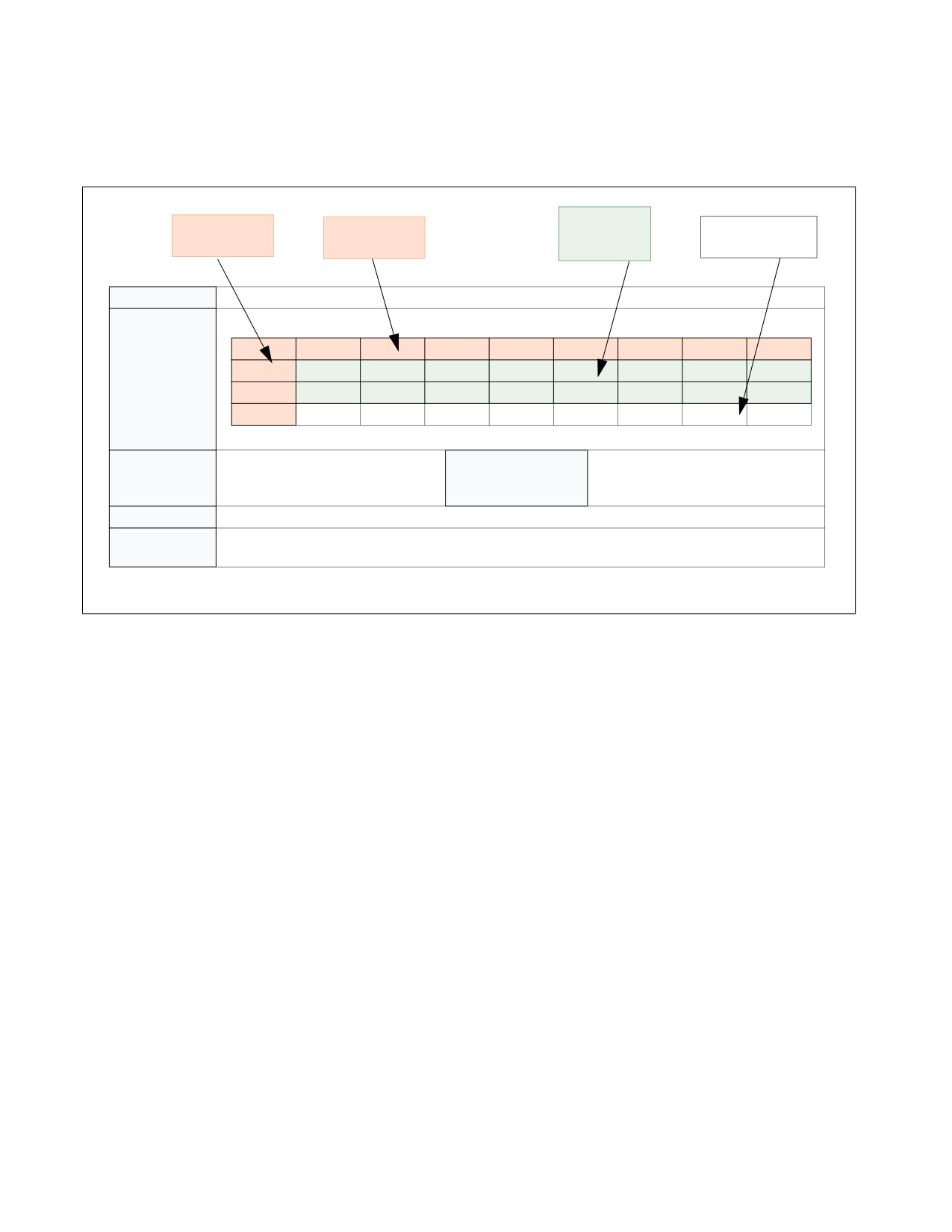
INTEL® PROCESSOR TRACE
33.4.2 Packet Definitions
The following description of packet definitions are in tabular format. Figure 33-3 explains how to interpret them.
Packet bits listed as “RSVD” are not guaranteed to be 0.
Header bits
Byte Number
Bit Number
Payload in White
in Green
Name
Packet name
Packet Format
7
6
5
4
3
2
1
0
0
0
1
0
1
0
1
0
1
1
1
1
0
0
0
1
1
0
2
0
1
0
0
0
1
1
0
Description of fields
Dependencies
Depends on packet generation con-
Generation Scenario
Which instructions, events, or other
figuration enable controls or other
scenarios can cause this packet to be
bits (Section 33.2.6).
generated.
Description
Description of the packet, including the purpose it serves, meaning of the information or payload, etc
Application
How a decoder should apply this packet. It may bind to a specific instruction from the binary, or to
another packet in the stream, or have other implications on decode
Figure 33-3. Interpreting Tabular Definition of Packet Format
33-38
Vol. 3C
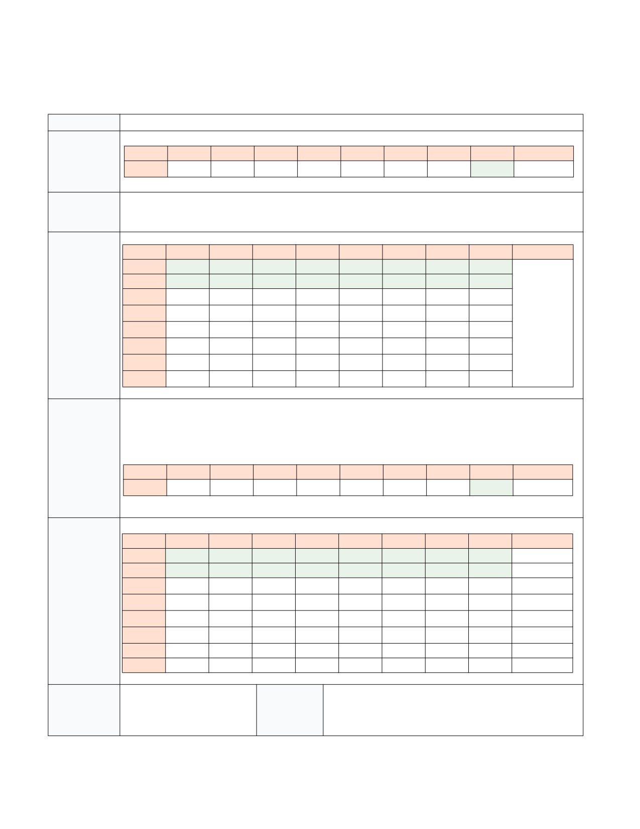
INTEL® PROCESSOR TRACE
33.4.2.1 Taken/Not-taken (TNT) Packet
Table 33-16. TNT Packet Definition
Name
Taken/Not-taken (TNT) Packet
Packet Format
7
6
5
4
3
2
1
0
0
1
B1
B2
B3
B4
B5
B6
0
Short TNT
B1…BN represent the last N conditional branch or compressed RET (Section 33.4.2.2) results, such that B1 is oldest
and BN is youngest. The short TNT packet can contain from 1 to 6 TNT bits. The long TNT packet can contain from
1 to 47 TNT bits.
7
6
5
4
3
2
1
0
0
0
0
0
0
0
0
1
0
Long TNT
1
1
0
1
0
0
0
1
1
2
B40
B41
B42
B43
B44
B45
B46
B47
3
B32
B33
B34
B35
B36
B37
B38
B39
4
B24
B25
B26
B27
B28
B29
B30
B31
5
B16
B17
B18
B19
B20
B21
B22
B23
6
B8
B9
B10
B11
B12
B13
B14
B15
7
1
B1
B2
B3
B4
B5
B6
B7
Irrespective of how many TNT bits is in a packet, the last valid TNT bit is followed by a trailing 1, or Stop bit, as
shown above. If the TNT packet is not full (fewer than 6 TNT bits for the Short TNT, or fewer than 47 TNT bits for
the Long TNT), the Stop bit moves up, and the trailing bits of the packet are filled with 0s. Examples of these
“partial TNTs” are shown below. An implementation may choose to use long TNTs, short TNTs, or both.
7
6
5
4
3
2
1
0
0
0
0
1
B1
B2
B3
B4
0
Short TNT
7
6
5
4
3
2
1
0
0
0
0
0
0
0
0
1
0
Long TNT
1
1
0
1
0
0
0
1
1
2
B24
B25
B26
B27
B28
B29
B30
B31
3
B16
B17
B18
B19
B20
B21
B22
B23
4
B8
B9
B10
B11
B12
B13
B14
B15
5
1
B1
B2
B3
B4
B5
B6
B7
6
0
0
0
0
0
0
0
0
7
0
0
0
0
0
0
0
0
Dependencies
PacketEn &&
Generation
On a conditional branch or compressed RET, if it fills the TNT.
~IA32_RTIT_CTL.DisTNT
Scenario
Also, partial TNTs may be generated at any time, as a result of
other packets being generated, or certain micro-architectural
conditions occurring, before the TNT is full.
Vol. 3C
33-39
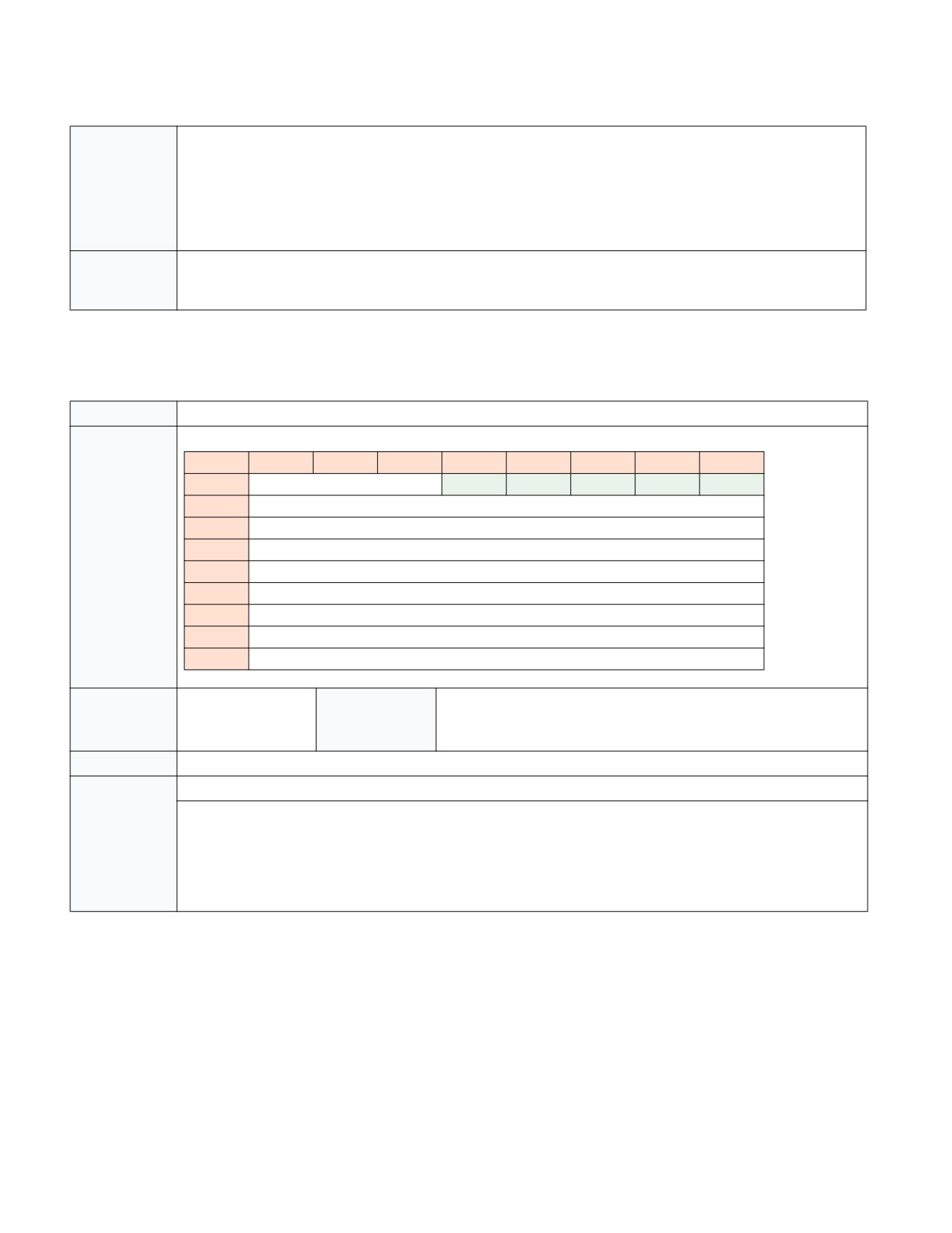
INTEL® PROCESSOR TRACE
Table 33-16. TNT Packet Definition (Contd.)
Description
Provides the taken/not-taken results for the last 1..6 (Short TNT) or 1..47 (Long TNT) conditional branches (Jcc,
J*CXZ, or LOOP) or compressed RETs (Section 33.4.2.2). The TNT payload bits should be interpreted as follows:
•
1 indicates a taken conditional branch, or a compressed RET
•
0 indicates a not-taken conditional branch
TNT payload bits are stored internal to the processor in a TNT buffer, until either the buffer is filled or another
packet is to be generated. In either case a TNT packet holding the buffered bits will be emitted, and the TNT buffer
will be marked as empty.
Application
Each valid payload bit (that is, bits between the header bits and the trailing Stop bit) applies to an upcoming condi-
tional branch or RET instruction. Once a decoder consumes a TNT packet with N valid payload bits, these bits should
be applied to (and hence provide the destination for) the next N conditional branches or RETs.
33.4.2.2 Target IP (TIP) Packet
Table 33-17. IP Packet Definition
Name
Target IP (TIP) Packet
Packet Format
7
6
5
4
3
2
1
0
0
IPBytes
0
1
1
0
1
1
TargetIP[7:0]
2
TargetIP[15:8]
3
TargetIP[23:16]
4
TargetIP[31:24]
5
TargetIP[39:32]
6
TargetIP[47:40]
7
TargetIP[55:48]
8
TargetIP[63:56]
Dependencies
PacketEn
Generation Sce-
Indirect branch (including un-compressed RET), far branch, interrupt,
nario
exception, INIT, SIPI, VM exit, VM entry, TSX abort, EENTER, EEXIT, ERE-
SUME, AEX1.
Description
Provides the target for some control flow transfers
Application
Anytime a TIP is encountered, it indicates that control was transferred to the IP provided in the payload.
The source of this control flow change, and hence the IP or instruction to which it binds, depends on the packets
that precede the TIP. If a TIP is encountered and all preceding packets have already been bound, then the TIP will
apply to the upcoming indirect branch, far branch, or VMRESUME. However, if there was a preceding FUP that
remains unbound, it will bind to the TIP. Here, the TIP provides the target of an asynchronous event or TSX abort
that occurred at the IP given in the FUP payload. Note that there may be other packets, in addition to the FUP, which
will bind to the TIP packet. See the packet application descriptions for other packets for details.
NOTES:
1. EENTER, EEXIT, ERESUME, AEX would be possible only for a debug enclave.
IP Compression
The IP payload in a TIP. FUP, TIP.PGE, or TIP.PGD packet can vary in size, based on the mode of execution, and the
use of IP compression. IP compression is an optional compression technique the processor may choose to employ
to reduce bandwidth. With IP compression, the IP to be represented in the payload is compared with the last IP sent
out, via any of FUP, TIP, TIP.PGE, or TIP.PGD. If that previous IP had the same upper (most significant) address
bytes, those matching bytes may be suppressed in the current packet. The processor maintains an internal state of
the “Last IP” that was encoded in trace packets, thus the decoder will need to keep track of the “Last IP” state in
33-40
Vol. 3C

INTEL® PROCESSOR TRACE
software, to match fidelity with packets generated by hardware. “Last IP” is initialized to zero, hence if the first IP
in the trace may be compressed if the upper bytes are zeroes.
The “IPBytes” field of the IP packets (FUP, TIP, TIP.PGE, TIP.PGD) serves to indicate how many bytes of payload are
provided, and how the decoder should fill in any suppressed bytes. The algorithm for reconstructing the IP for a
TIP/FUP packet is shown in the table below.
Table 33-18. FUP/TIP IP Reconstruction
IPBytes
Uncompressed IP Value
63:56
55:48
47:40
39:32
31:24
23:16
15:8
7:0
000b
None, IP is out of context
001b
Last IP[63:16]
IP Payload[15:0]
010b
Last IP[63:32]
IP Payload[31:0]
011b
IP Payload[47] extended
IP Payload[47:0]
100b
Last IP [63:48]
IP Payload[47:0]
101b
Reserved
110b
IP Payload[63:0]
111b
Reserved
The processor-internal Last IP state is guaranteed to be reset to zero when a PSB is sent out. This means that the
IP that follows the PSB with either be un-compressed (011b or 110b, see Table 33-18), or compressed against
zero.
At times, “IPbytes” will have a value of 0. As shown above, this does not mean that the IP payload matches the full
address of the last IP, but rather that the IP for this packet was suppressed. This is used for cases where the IP that
applies to the packet is out of context. An example is the TIP.PGD sent on a SYSCALL, when tracing only USR code.
In that case, no TargetIP will be included in the packet, since that would expose an instruction point at CPL = 0.
When the IP payload is suppressed in this manner, Last IP is not cleared, and instead refers to the last IP packet
with a non-zero IPBytes field.
On processors that support a maximum linear address size of 32 bits, IP payloads may never exceed 32 bits
(IPBytes <= 010b).
Indirect Transfer Compression for Returns (RET)
In addition to IP compression, TIP packets for near return (RET) instructions can also be compressed. If the RET
target matches the next IP of the corresponding CALL, then the TIP packet is unneeded, since the decoder can
deduce the target IP by maintaining a CALL/RET stack of its own.
When a RET is compressed, a Taken indication is added to the TNT buffer. Because the RET generates no TIP
packet, it also does not update the internal Last IP value, and thus the decoder should treat it the same way. If the
RET is not compressed, it will generate a TIP packet (just like when RET compression is disabled, via
IA32_RTIT_CTL.DisRETC).
A CALL/RET stack can be maintained by the decoder by doing the following:
1. Allocate space to store 64 RET targets.
2. For near CALLs, push the Next IP onto the stack. Once the stack is full, new CALLs will force the oldest entry off
the end of the stack, such that only the youngest 64 entries are stored. Note that this excludes zero-length
CALLs, which are direct near CALLs with displacement zero (to the next IP). These CALLs typically don’t have
matching RETs.
3. For near RETs, pop the top (youngest) entry off the stack. This will be the expected target of the RET.
In cases where a RET is compressed, the RET target is guaranteed to match the expected target from 3) above. If
the target is not compressed, a TIP packet will be generated with the RET target, which may differ from the
expected target in some cases.
Vol. 3C
33-41

INTEL® PROCESSOR TRACE
The hardware ensures that packets read by the decoder will always have seen the CALL that corresponds to any
compressed RET. The processor will never compress a RET across a PSB, a buffer overflow, or scenario where Pack-
etEn=0. This means that a RET whose corresponding CALL executed while PacketEn=0, or before the last PSB, etc.,
will not be compressed.
If the CALL/RET stack is manipulated or corrupted by software, and thereby causes a RET to transfer control to a
target that is inconsistent with the CALL/RET stack, then the RET will not be compressed, and will produce a TIP
packet. This can happen, for example, if software executes a PUSH instruction to push a target onto the stack, and
a later RET uses this target.
For processors that employ deferred TIPs (Section 33.4.2.3), an uncompressed RET will not be deferred, and hence
will force out any accumulated TNTs or TIPs. This serves to avoid ambiguity, and make clear to the decoder whether
the near RET was compressed, and hence a bit in the in-progress TNT should be consumed, or uncompressed, in
which case there will be no in-progress TNT and thus a TIP should be consumed.
Note that in the unlikely case that a RET executes in a different execution mode than the associated CALL, the
decoder will need to model the same behavior with its CALL stack. For instance, if a CALL executes in 64-bit mode,
a 64-bit IP value will be pushed onto the software stack. If the corresponding RET executes in 32-bit mode, then
only the lower 32 target bits will be popped off of the stack, which may mean that the RET does not go to the CALL’s
Next IP. This is architecturally correct behavior, and this RET could be compressed, thus the decoder should match
this behavior.
33.4.2.3 Deferred TIPs
The processor may opt to defer sending out the TNT when TIPs are generated. Thus, rather than sending a partial
TNT followed by a TIP, both packets will be deferred while the TNT accumulates more Jcc/RET results. Any number
of TIP packets may be accumulated this way, such that only once the TNT is filled, or once another packet (e.g.,
FUP) is generated, the TNT will be sent, followed by all the deferred TIP packets, and finally terminated by the other
packet(s) that forced out the TNT and TIP packets. Generation of many other packets (see list below) will force out
the TNT and any accumulated TIP packets. This is an optional optimization in hardware to reduce the bandwidth
consumption, and hence the performance impact, incurred by tracing.
Table 33-19. TNT Examples with Deferred TIPs
Code Flow
Packets, Non-Deferred TIPS
Packets, Deferred TIPS
0x1000 cmp %rcx, 0
0x1004 jnz Foo // not-taken
TNT(0b0), TIP(0x1308)
0x1008 jmp %rdx
0x1308 cmp %rcx, 1
0x130c jnz Bar // not-taken
0x1310 cmp %rcx, 2
0x1314 jnz Baz // taken
0x1500 cmp %eax, 7
TNT(0b010), TIP(0x1100)
0x1504 jg Exit // not-taken
0x1508 jmp %r15
0x1100 cmp %rbx, 1
0x1104 jg Start // not-taken
0x1108 add %rcx, %eax
TNT(0b0), FUP(0x110c),
0x110c … // an asynchronous Interrupt arrives
TIP(0xcc00)
INThandler:
TNT(0b00100), TIP(0x1308),
TIP(0x1100), FUP(0x110c),
0xcc00 pop %rdx
TIP(0xcc00)
33-42
Vol. 3C

INTEL® PROCESSOR TRACE
33.4.2.4 Packet Generation Enable (TIP.PGE) Packet
Table 33-20. TIP.PGE Packet Definition
Name
Target IP - Packet Generation Enable (TIP.PGE) Packet
Packet Format
7
6
5
4
3
2
1
0
0
IPBytes
1
0
0
0
1
1
TargetIP[7:0]
2
TargetIP[15:8]
3
TargetIP[23:16]
4
TargetIP[31:24]
5
TargetIP[39:32]
6
TargetIP[47:40]
7
TargetIP[55:48]
8
TargetIP[63:56]
Dependencies
PacketEn transitions to 1
Generation
Any branch instruction, control flow transfer, or MOV
Scenario
CR3 that sets PacketEn, a WRMSR that enables
packet generation and sets PacketEn
Description
Indicates that PacketEn has transitioned to 1. It provides the IP at which the tracing begins.
This can occur due to any of the enables that comprise PacketEn transitioning from 0 to 1, as long as all the others
are asserted. Examples:
• TriggerEn: This is set on software write to set IA32_RTIT_CTL.TraceEn as long as the Stopped and Error bits in
IA32_RTIT_STATUS are clear. The IP payload will be the Next IP of the WRMSR.
• FilterEn: This is set when software jumps into the tracing region. This region is defined by enabling IP filtering in
IA32_RTIT_CTL.ADDRn_CFG, and defining the range in IA32_RTIT_ADDRn_[AB], see. Section 33.2.5.3. The
IP payload will be the target of the branch.
• ContextEn: This is set on a CPL change, a CR3 write or any other means of changing ContextEn. The IP payload
will be the Next IP of the instruction that changes context if it is not a branch, otherwise it will be the target of
the branch.
Application
TIP.PGE packets bind to the instruction at the IP given in the payload.
Vol. 3C
33-43

INTEL® PROCESSOR TRACE
33.4.2.5 Packet Generation Disable (TIP.PGD) Packet
Table 33-21. TIP.PGD Packet Definition
Name
Target IP - Packet Generation Disable (TIP.PGD) Packet
Packet Format
7
6
5
4
3
2
1
0
0
IPBytes
0
0
0
0
1
1
TargetIP[7:0]
2
TargetIP[15:8]
3
TargetIP[23:16]
4
TargetIP[31:24]
5
TargetIP[39:32]
6
TargetIP[47:40]
7
TargetIP[55:48]
8
TargetIP[63:56]
Dependencies
PacketEn transitions to
Generation
Any branch instruction, control flow transfer, or MOV CR3 that clears
0
Scenario
PacketEn, a WRMSR that disables packet generation and clears PacketEn
Description
Indicates that PacketEn has transitioned to 0. It will include the IP at which the tracing ends, unless ContextEn= 0 or
TraceEn=0 at the conclusion of the instruction or event that cleared PacketEn.
PacketEn can be cleared due to any of the enables that comprise PacketEn transitioning from 1 to 0. Examples:
• TriggerEn: This is cleared on software write to clear IA32_RTIT_CTL.TraceEn, or when
IA32_RTIT_STATUS.Stopped is set, or on operational error. The IP payload will be suppressed in this case, and the
“IPBytes” field will have the value 0.
• FilterEn: This is cleared when software jumps out of the tracing region. This region is defined by enabling IP
filtering in IA32_RTIT_CTL.ADDRn_CFG, and defining the range in IA32_RTIT_ADDRn_[AB], see. Section 33.2.5.3.
The IP payload will depend on the type of the branch. For conditional branches, the payload is suppressed
(IPBytes = 0), and in this case the destination can be inferred from the disassembly. For any other type of branch,
the IP payload will be the target of the branch.
• ContextEn: This can happen on a CPL change, a CR3 write or any other means of changing ContextEn. See
Section 33.2.5.3 for details. In this case, when ContextEn is cleared, there will be no IP payload. The “IPBytes”
field will have value 0.
Note that, in cases where a branch that would normally produce a TIP packet (i.e., far transfer, indirect branch, inter-
rupt, etc) or TNT update (conditional branch or compressed RT) causes PacketEn to transition from 1 to 0, the TIP or
TNT bit will be replaced with TIP.PGD. The payload of the TIP.PGD will be the target of the branch, unless the result
of the instruction causes TraceEn or ContextEn to be cleared (ie, SYSCALL when IA32_RTIT_CTL.OS=0, In the case
where a conditional branch clears FilterEn and hence PacketEn, there will be no TNT bit for this branch, replaced
instead by the TIP.PGD.
Application
TIP.PGD can be produced by any branch instructions, as well as some non-branch instructions, that clear PacketEn.
When produced by a branch, it replaces any TIP or TNT update that the branch would normally produce.
In cases where there is an unbound FUP preceding the TIP.PGD, then the TIP.PGD is part of compound operation (i.e.,
asynchronous event or TSX abort) which cleared PacketEn. For most such cases, the TIP.PGD is simply replacing a
TIP, and should be treated the same way. The TIP.PGD may or may not have an IP payload, depending on whether
the operation cleared ContextEn.
If there is not an associated FUP, the binding will depend on whether there is an IP payload. If there is an IP payload,
then the TIP.PGD should be applied to either the next direct branch whose target matches the TIP.PGD payload, or
the next branch that would normally generate a TIP or TNT packet. If there is no IP payload, then the TIP.PGD should
apply to the next branch or MOV CR3 instruction.
33-44
Vol. 3C

INTEL® PROCESSOR TRACE
33.4.2.6 Flow Update (FUP) Packet
Table 33-22. FUP Packet Definition
Name
Flow Update (FUP) Packet
Packet Format
7
6
5
4
3
2
1
0
0
IPBytes
1
1
1
0
1
1
IP[7:0]
2
IP[15:8]
3
IP[23:16]
4
IP[31:24]
5
IP[39:32]
6
IP[47:40]
7
IP[55:48]
8
IP[63:56]
Dependencies
TriggerEn && ContextEn.
Generation
Asynchronous Events (interrupts, exceptions, INIT, SIPI, SMI, VM exit,
(Typically depends on
Scenario
#MC), PSB+, XBEGIN, XEND, XABORT, XACQUIRE, XRELEASE, EENTER,
BranchEn and FilterEn as well,
EEXIT, ERESUME, EEE, AEX,1, INTO, INT1, INT3, INT n, a WRMSR that
see Section 33.2.5, Section
disables packet generation.
33.4.2.21, and Section
33.4.2.22 for details.)
Description
Provides the source address for asynchronous events, and some other instructions. Is never sent alone, always sent
with an associated TIP or MODE packet, and potentially others.
Application
FUP packets provide the IP to which they bind. However, they are never standalone, but are coupled with other
packets.
In TSX cases, the FUP is immediately preceded by a MODE.TSX, which binds to the same IP. A TIP will follow only in
the case of TSX aborts, see Section 33.4.2.8 for details.
Otherwise, FUPs are part of compound packet events (see Section 33.4.1). In these compound cases, the FUP pro-
vides the source IP for an instruction or event, while a following TIP (or TIP.PGD) packet will provide the destination
IP. Other packets may be included in the compound event between the FUP and TIP.
NOTES:
1. EENTER, EEXIT, ERESUME, EEE, AEX apply only if Intel Software Guard Extensions is supported.
FUP IP Payload
Flow Update Packet gives the source address of an instruction when it is needed. In general, branch instructions do
not need a FUP, because the source address is clear from the disassembly. For asynchronous events, however, the
source address cannot be inferred from the source, and hence a FUP will be sent. Table 33-23 illustrates cases
where FUPs are sent, and which IP can be expected in those cases.
Vol. 3C
33-45

INTEL® PROCESSOR TRACE
Table 33-23. FUP Cases and IP Payload
Event
Flow Update IP
Comment
External Interrupt, NMI/SMI, Traps,
Address of next instruction (Next IP) that
Functionally, this matches the LBR FROM field
Machine Check (trap-like), INIT/SIPI
would have been executed
value and also the EIP value which is saved onto
the stack.
Exceptions/Faults, Machine check
Address of the instruction which took the
This matches the similar functionality of LBR
(fault-like)
FROM field value and also the EIP value which is
exception/fault (Current IP)
saved onto the stack.
Software Interrupt
Address of the software interrupt instruction
This matches the similar functionality of LBR
(Current IP)
FROM field value, but does not match the EIP
value which is saved onto the stack (Next
Linear Instruction Pointer - NLIP).
EENTER, EEXIT, ERESUME, Enclave
Current IP of the instruction
This matches the LBR FROM field value and also
Exiting Event (EEE), AEX1
the EIP value which is saved onto the stack.
XACQUIRE
Address of the X* instruction
XRELEASE, XBEGIN, XEND,
Current IP
XABORT, other transactional abort
#SMI
IP that is saved into SMRAM
WRMSR that clears TraceEn, PSB+
Current IP
NOTES:
1. Information on EENTER, EEXIT, ERESUME, EEE, Asynchronous Enclave eXit (AEX) can be found in the Intel® 64
and IA-32 Architectures Software Developer’s Manual, Volume 3D.
On a canonical fault due to sequentially fetching an instruction in non-canonical space (as opposed to jumping to
non-canonical space), the IP of the fault (and thus the payload of the FUP) will be a non-canonical address. This is
consistent with what is pushed on the stack for such faulting cases.
If there are post-commit task switch faults, the IP value of the FUP will be the original IP when the task switch
started. This is the same value as would be seen in the LBR_FROM field. But it is a different value as is saved on the
stack or VMCS.
33-46
Vol. 3C

INTEL® PROCESSOR TRACE
33.4.2.7 Paging Information (PIP) Packet
Table 33-24. PIP Packet Definition
Name
Paging Information (PIP) Packet
Packet Format
7
6
5
4
3
2
1
0
0
0
0
0
0
0
0
1
0
1
0
1
0
0
0
0
1
1
2
CR3[11:5] or 0
RSVD/NR
3
CR3[19:12]
4
CR3[27:20]
5
CR3[35:28]
6
CR3[43:36]
7
CR3[51:44]
Dependencies
TriggerEn && ContextEn &&
Generation
MOV CR3, Task switch, INIT, SIPI, PSB+, VM exit,
IA32_RTIT_CTL.OS
Scenario
VM entry
Description
The CR3 payload shown includes only the address portion of the CR3 value. For PAE paging, CR3[11:5] are thus
included. For other paging modes (32-bit and 4-level paging1), these bits are 0.
This packet holds the CR3 address value. It will be generated on operations that modify CR3:
• MOV CR3 operation
• Task Switch
• INIT and SIPI
• VM exit, if “conceal VMX from PT” VM-exit control is 0 (see Section 33.5.1)
• VM entry, if “conceal VMX from PT” VM-entry control is 0
PIPs are not generated, despite changes to CR3, on SMI and RSM. This is due to the special behavior on these oper-
ations, see Section 33.2.9.3 for details. Note that, for some cases of task switch where CR3 is not modified, no PIP
will be produced.
The purpose of the PIP is to indicate to the decoder which application is running, so that it can apply the proper
binaries to the linear addresses that are being traced.
The PIP packet contains the new CR3 value when CR3 is written.
PIPs generated by VM entries set the NR bit. PIPs generated in VMX non-root operation set the NR bit if the “con-
ceal VMX from PT” VM-execution control is 0 (see Section 33.5.1). All other PIPs clear the NR bit.
Application
The purpose of the PIP packet is to help the decoder uniquely identify what software is running at any given time.
When a PIP is encountered, a decoder should do the following:
1) If there was a prior unbound FUP (that is, a FUP not preceded by a packet such as MODE.TSX that consumes it,
and it hence pairs with a TIP that has not yet been seen), then this PIP is part of a compound packet event (Section
33.4.1). Find the ending TIP and apply the new CR3/NR values to the TIP payload IP.
2) Otherwise, look for the next MOV CR3, far branch, or VMRESUME/VMLAUNCH in the disassembly, and apply the
new CR3 to the next (or target) IP.
For examples of the packets generated by these flows, see Section 33.7.
NOTES:
1. Earlier versions of this manual used the term “IA-32e paging” to identify 4-level paging.
33.4.2.8 MODE Packets
MODE packets keep the decoder informed of various processor modes about which it needs to know in order to
properly manage the packet output, or to properly disassemble the associated binaries. MODE packets include a
header and a mode byte, as shown below.
Vol. 3C
33-47

INTEL® PROCESSOR TRACE
Table 33-25. General Form of MODE Packets
7
6
5
4
3
2
1
0
0
1
0
0
1
1
0
0
1
1
Leaf ID
Mode
The MODE Leaf ID indicates which set of mode bits are held in the lower bits.
MODE.Exec Packet
Table 33-26. MODE.Exec Packet Definition
Name
MODE.Exec Packet
Packet Format
7
6
5
4
3
2
1
0
0
1
0
0
1
1
0
0
1
1
0
0
0
Reserved
IF
CS.D
(CS.L & LMA)
MODE Leaf ID is '000.
Dependencies
TriggerEn
Generation
Any operation that changes the CS.L, CS.D, or EFER.LMA, if
&&
Scenario
IA32_RTIT_CTL.BranchEn=1.
ContextEn
Any operation that changes RFLAGS.IF, if IA32_RTIT_CTL.EventEn=1.
&& FilterEn
Any TIP.PGE scenario, such that any of the mode bits tracked may have changed
since the last MODE.Exec.
Description
Indicates whether software is in 16, 32, or 64-bit mode, by providing the CS.D and (CS.L & IA32_EFER.LMA) values.
Essential for the decoder to properly disassemble the associated binary. Further, if CPUID.0x14.0.EBX[6]=1 (“Event
Trace Support”), it indicates when interrupts are masked by providing the RFLAGS.IF value.
MODE.Exec is sent at the time of a mode change, if dependencies are met at the time, otherwise it is sent when
tracing resumes. In the former case, the MODE.Exec packet is generated along with other packets that result from
the operation that changes the mode, and is guaranteed to be followed by a TIP or TIP.PGE for branch operations, or
a FUP for non-branch operations (CLI, STI, or POPF if EventEn=1). In cases where the mode changes while filtering
dependencies are not met, the processor ensures that the decoder doesn't lose track of the mode by sending any
needed MODE.Exec once tracing resumes (preceding the TIP.PGE, if BranchEn=1). The processor may opt to sup-
press the MODE.Exec when tracing resumes if the mode matches that of the last MODE.Exec packet.
MODE.Exec packets are generated on CS.L, CS.D, or EFER.LMA changes only if control flow tracing is enabled
(BranchEn=1). This is essential for the decoder to properly disassemble the associated binary.
CS.D
(CS.L & IA32_EFER.LMA)
Addressing Mode
1
1
N/A
0
1
64-bit mode
1
0
32-bit mode
0
0
16-bit mode
MODE.Exec packets are generated on interrupt flag (RFLAGS.IF) changes only if event tracing is enabled
(EventEn=1).
Application
MODE.Exec always precedes an IP packet (TIP, TIP.PGE, or FUP). The mode change applies to the IP address in the
payload of the IP packet. When MODE.Exec is followed by a FUP, it is a stand-alone FUP and should be consumed by
the MODE.Exec.
33-48
Vol. 3C

INTEL® PROCESSOR TRACE
MODE.TSX Packet
Table 33-27. MODE.TSX Packet Definition
Name
MODE.TSX Packet
Packet Format
7
6
5
4
3
2
1
0
0
1
0
0
1
1
0
0
1
1
0
0
1
0
0
0
TXAbort
InTX
Dependencies
TriggerEn && ContextEn
Generation
XBEGIN, XEND, XABORT, XACQUIRE, XRELEASE, if InTX
Scenario
changes, Asynchronous TSX Abort, PSB+
Description
Indicates when a TSX transaction (either HLE or RTM) begins, commits, or aborts. Instructions executed transaction-
ally will be “rolled back” if the transaction is aborted.
TXAbort
InTX
Implication
1
1
N/A
0
1
Transaction begins, or executing transactionally
1
0
Transaction aborted
0
0
Transaction committed, or not executing transactionally
Application
If PacketEn=1, MODE.TSX always immediately precedes a FUP. If the TXAbort bit is zero, then the mode change
applies to the IP address in the payload of the FUP. If TXAbort=1, then the FUP will be followed by a TIP, and the
mode change will apply to the IP address in the payload of the TIP.
MODE.TSX packets may be generated when PacketEn=0, due to FilterEn=0. In this case, only the last MODE.TSX
generated before TIP.PGE need be applied.
Vol. 3C
33-49
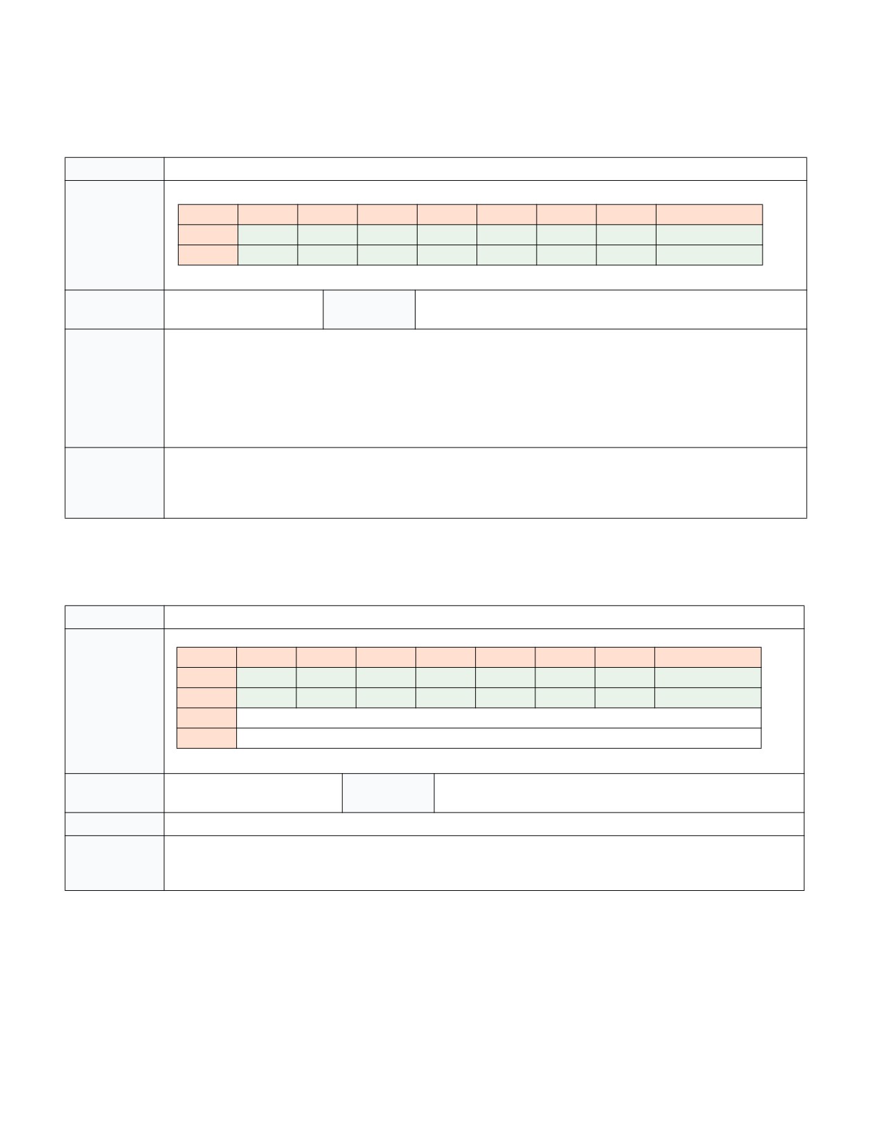
INTEL® PROCESSOR TRACE
33.4.2.9 TraceStop Packet
Table 33-28. TraceStop Packet Definition
Name
TraceStop Packet
Packet Format
7
6
5
4
3
2
1
0
0
0
0
0
0
0
0
1
0
1
1
0
0
0
0
0
1
1
Dependencies
TriggerEn && ContextEn
Generation
Taken branch with target in TraceStop IP region, MOV CR3 in TraceS-
Scenario
top IP region, or WRMSR that sets TraceEn in TraceStop IP region.
Description
Indicates when software has entered a user-configured TraceStop region.
When the IP matches a TraceStop range while ContextEn and TriggerEn are set, a TraceStop action occurs. This dis-
ables tracing by setting IA32_RTIT_STATUS.Stopped, thereby clearing TriggerEn, and causes a TraceStop
packet to be generated.
The TraceStop action also forces FilterEn to 0. Note that TraceStop may not force a flush of internally buffered
packets, and thus trace packet generation should still be manually disabled by clearing IA32_RTIT_CTL.TraceEn
before examining output. See Section 33.2.5.3 for more details.
Application
If TraceStop follows a TIP.PGD (before the next TIP.PGE), then it was triggered either by the instruction that cleared
PacketEn, or it was triggered by some later instruction that executed while FilterEn=0. In either case, the TraceStop
can be applied at the IP of the TIP.PGD (if any).
If TraceStop follows a TIP.PGE (before the next TIP.PGD), it should be applied at the last known IP.
33.4.2.10 Core:Bus Ratio (CBR) Packet
Table 33-29. CBR Packet Definition
Name
Core:Bus Ratio (CBR) Packet
Packet Format
7
6
5
4
3
2
1
0
0
0
0
0
0
0
0
1
0
1
0
0
0
0
0
0
1
1
2
Core:Bus Ratio
3
Reserved
Dependencies
TriggerEn
Generation
After any frequency change, on C-state wake up, PSB+, and after
Scenario
enabling trace packet generation.
Description
Indicates the core:bus ratio of the processor core. Useful for correlating wall-clock time and cycle time.
Application
The CBR packet indicates the point in the trace when a frequency transition has occurred. On some implementa-
tions, software execution will continue during transitions to a new frequency, while on others software execution
ceases during frequency transitions. There is not a precise IP provided, to which to bind the CBR packet.
33-50
Vol. 3C

INTEL® PROCESSOR TRACE
33.4.2.11 Timestamp Counter (TSC) Packet
Table 33-30. TSC Packet Definition
Name
Timestamp Counter (TSC) Packet
Packet Format
7
6
5
4
3
2
1
0
0
0
0
0
1
1
0
0
1
1
SW TSC[7:0]
2
SW TSC[15:8]
3
SW TSC[23:16]
4
SW TSC[31:24]
5
SW TSC[39:32]
6
SW TSC[47:40]
7
SW TSC[55:48]
Dependencies
IA32_RTIT_CTL.TSCEn &&
Generation
Sent after any event that causes the processor clocks or Intel PT timing
TriggerEn
Scenario
packets (such as MTC or CYC) to stop, This may include P-state changes,
wake from C-state, or clock modulation. Also on transition of TraceEn
from 0 to 1.
Description
When enabled by software, a TSC packet provides the lower 7 bytes of the current TSC value, as returned by the
RDTSC instruction. This may be useful for tracking wall-clock time, and synchronizing the packets in the log with
other timestamped logs.
Application
TSC packet provides a wall-clock proxy of the event which generated it (packet generation enable, sleep state wake,
etc). In all cases, TSC does not precisely indicate the time of any control flow packets; however, all preceding packets
represent instructions that executed before the indicated TSC time, and all subsequent packets represent instruc-
tions that executed after it. There is not a precise IP to which to bind the TSC packet.
Vol. 3C
33-51

INTEL® PROCESSOR TRACE
33.4.2.12 Mini Time Counter (MTC) Packet
Table 33-31. MTC Packet Definition
Name
Mini time Counter (MTC) Packet
Packet Format
7
6
5
4
3
2
1
0
0
0
1
0
1
1
0
0
1
1
CTC[N+7:N]
Dependencies
IA32_RTIT_CTL.MTCEn &&
Generation
Periodic, based on the core crystal clock, or Always Running Timer
TriggerEn
Scenario
(ART).
Description
When enabled by software, an MTC packet provides a periodic indication of wall-clock time. The 8-bit CTC (Common
Timestamp Copy) payload value is set to (ART >> N) & FFH. The frequency of the ART is related to the Maximum
Non-Turbo frequency, and the ratio can be determined from CPUID leaf 15H, as described in Section 33.8.3.
Software can select the threshold N, which determines the MTC frequency by setting the IA32_RTIT_CTL.MTCFreq
field (see Section 33.2.8.2) to a supported value using the lookup enumerated by CPUID (see Section 33.3.1).
See Section 33.8.3 for details on how to use the MTC payload to track TSC time.
MTC provides 8 bits from the ART, starting with the bit selected by MTCFreq to dictate the frequency of the packet.
Whenever that 8-bit range being watched changes, an MTC packet will be sent out with the new value of that 8-bit
range. This allows the decoder to keep track of how much wall-clock time has elapsed since the last TSC packet was
sent, by keeping track of how many MTC packets were sent and what their value was. The decoder can infer the
truncated bits, CTC[N-1:0], are 0 at the time of the MTC packet.
There are cases in which MTC packet can be dropped, due to overflow or other micro-architectural conditions. The
decoder should be able to recover from such cases by checking the 8-bit payload of the next MTC packet, to deter-
mine how many MTC packets were dropped. It is not expected that >256 consecutive MTC packets should ever be
dropped.
Application
MTC does not precisely indicate the time of any other packet, nor does it bind to any IP. However, all preceding pack-
ets represent instructions or events that executed before the indicated ART time, and all subsequent packets repre-
sent instructions that executed after, or at the same time as, the ART time.
33-52
Vol. 3C

INTEL® PROCESSOR TRACE
33.4.2.13 TSC/MTC Alignment (TMA) Packet
Table 33-32. TMA Packet Definition
Name
TSC/MTC Alignment (TMA) Packet
Packet Format
7
6
5
4
3
2
1
0
0
0
0
0
0
0
0
1
0
1
0
1
1
1
0
0
1
1
2
CTC[7:0]
3
CTC[15:8]
4
Reserved
0
5
FastCounter[7:0]
6
Reserved
FC[8]
Dependencies
IA32_RTIT_CTL.MTCEn &&
Generation Sce-
Sent with any TSC packet.
IA32_RTIT_CTL.TSCEn && TriggerEn
nario
Description
The TMA packet serves to provide the information needed to allow the decoder to correlate MTC packets with TSC
packets. With this packet, when a MTC packet is encountered, the decoder can determine how many timestamp
counter ticks have passed since the last TSC or MTC packet. See Section 33.8.3.2 for details on how to make this cal-
culation.
Application
TMA is always sent immediately following a TSC packet, and the payload values are consistent with the TSC payload
value. Thus the application of TMA matches that of TSC.
Vol. 3C
33-53

INTEL® PROCESSOR TRACE
33.4.2.14 Cycle Count (CYC) Packet
Table 33-33. Cycle Count Packet Definition
Name
Cycle Count (CYC) Packet
Packet Format
7
6
5
4
3
2
1
0
0
Cycle Counter[4:0]
Exp
1
1
1
Cycle Counter[11:5]
Exp
2
Cycle Counter[18:12]
Exp
(if Exp = 1 in the previous byte)
Dependencies
IA32_RTIT_CTL.CYCEn &&
Generation Sce-
Can be sent at any time, though a maximum of one CYC packet is
TriggerEn
nario
sent per core clock cycle. See Section 33.3.6 for CYC-eligible packets.
Description
The Cycle Counter field increments at the same rate as the processor core clock ticks, but with a variable length for-
mat (using a trailing EXP bit field) and a range-capped byte length.
If the CYC value is less than 32, a 1-byte CYC will be generated, with Exp=0. If the CYC value is between 32 and
4095 inclusive, a 2-byte CYC will be generated, with byte 0 Exp=1 and byte 1 Exp=0. And so on.
CYC provides the number of core clocks that have passed since the last CYC packet. CYC can be configured to be
sent in every cycle in which an eligible packet is generated, or software can opt to use a threshold to limit the num-
ber of CYC packets, at the expense of some precision. These settings are configured using the
IA32_RTIT_CTL.CycThresh field (see Section 33.2.8.2). For details on Cycle-Accurate Mode, IPC calculation, etc, see
Section 33.3.6.
When CycThresh=0, and hence no threshold is in use, then a CYC packet will be generated in any cycle in which any
CYC-eligible packet is generated. The CYC packet will precede the other packets generated in the cycle, and provides
the precise cycle time of the packets that follow.
In addition to these CYC packets generated with other packets, CYC packets can be sent stand-alone. These packets
serve simply to update the decoder with the number of cycles passed, and are used to ensure that a wrap of the
processor’s internal cycle counter doesn’t cause cycle information to be lost. These stand-alone CYC packets do not
indicate the cycle time of any other packet or operation, and will be followed by another CYC packet before any
other CYC-eligible packet is seen.
When CycThresh>0, CYC packets are generated only after a minimum number of cycles have passed since the last
CYC packet. Once this threshold has passed, the behavior above resumes, where CYC will either be sent in the next
cycle that produces other CYC-eligible packets, or could be sent stand-alone.
When using CYC thresholds, only the cycle time of the operation (instruction or event) that generates the CYC
packet is truly known. Other operations simply have their execution time bounded: they completed at or after the
last CYC time, and before the next CYC time.
Application
CYC provides the offset cycle time (since the last CYC packet) for the CYC-eligible packet that follows. If another CYC
is encountered before the next CYC-eligible packet, the cycle values should be accumulated and applied to the next
CYC-eligible packet.
If a CYC packet is generated by a TNT, note that the cycle time provided by the CYC packet applies to the first
branch in the TNT packet.
33-54
Vol. 3C

INTEL® PROCESSOR TRACE
33.4.2.15 VMCS Packet
Table 33-34. VMCS Packet Definition
Name
VMCS Packet
Packet Format
7
6
5
4
3
2
1
0
0
0
0
0
0
0
0
1
0
1
1
1
0
0
1
0
0
0
2
VMCS pointer [19:12]
3
VMCS pointer [27:20]
4
VMCS pointer [35:28]
5
VMCS pointer [43:36]
6
VMCS pointer [51:44]
Dependencies
TriggerEn && ContextEn;
Generation Scenario
Generated on successful VMPTRLD, and optionally on PSB+, SMM
Also in VMX operation.
VM exits, and VM entries that return from SMM (see Section 33-
53).
Description
The VMCS packet provides a VMCS pointer for a decoder to determine the transition of code contexts:
• On a successful VMPTRLD (i.e., a VMPTRLD that doesn’t fault, fail, or VM exit), the VMCS packet contains the
logical processor’s VMCS pointer established by VMPTRLD (for subsequent execution of a VM guest context).
• An SMM VM exit loads the logical processor’s VMCS pointer with the SMM-transfer VMCS pointer. If the “conceal
VMX from PT” VM-exit control is 0 (see Section 33.5.1), a VMCS packet provides this pointer. See Section 33.6 on
tracing inside and outside STM.
• A VM entry that returns from SMM loads the logical processor’s VMCS pointer from a field in the SMM-transfer
VMCS. If the “conceal VMX from PT” VM-entry control is 0, a VMCS packet provides this pointer. Whether the
VM entry is to VMX root operation or VMX non-root operation is indicated by the PIP.NR bit.
A VMCS packet generated before a VMCS pointer has been loaded, or after the VMCS pointer has been cleared will
set all 64 bits in the VMCS pointer field.
VMCS packets will not be seen on processors with IA32_VMX_MISC[bit 14]=0, as these processors do not allow
TraceEn to be set in VMX operation.
Application
The purpose of the VMCS packet is to help the decoder uniquely identify changes in the executing software context
in situations that CR3 may not be unique.
When a VMCS packet is encountered, a decoder should do the following:
• If there was a prior unbound FUP (that is, a FUP not preceded by a packet such as MODE.TSX that consumes it, and
it hence pairs with a TIP that has not yet been seen), then this VMCS is part of a compound packet event (Section
33.4.1). Find the ending TIP and apply the new VMCS base pointer value to the TIP payload IP.
• Otherwise, look for the next VMPTRLD, VMRESUME, or VMLAUNCH in the disassembly, and apply the new VMCS
base pointer on the next VM entry.
For examples of the packets generated by these flows, see Section 33.7.
Vol. 3C
33-55
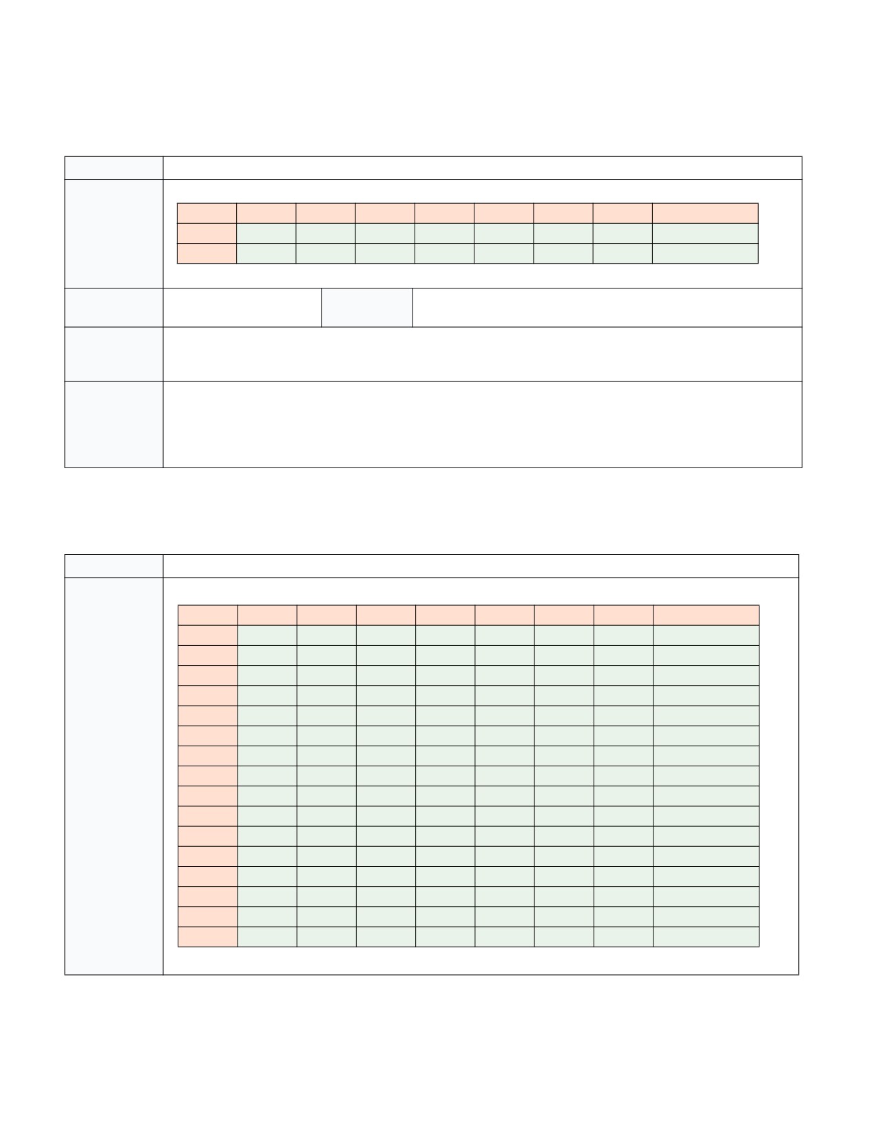
INTEL® PROCESSOR TRACE
33.4.2.16 Overflow (OVF) Packet
Table 33-35. OVF Packet Definition
Name
Overflow (OVF) Packet
Packet Format
7
6
5
4
3
2
1
0
0
0
0
0
0
0
0
1
0
1
1
1
1
1
0
0
1
1
Dependencies
TriggerEn
Generation
On resolution of internal buffer overflow
Scenario
Description
OVF simply indicates to the decoder that an internal buffer overflow occurred, and packets were likely lost. If
BranchEN= 1, OVF is followed by a FUP or TIP.PGE which will provide the IP at which packet generation resumes. See
Section 33.3.8.
Application
When an OVF packet is encountered, the decoder should skip to the IP given in the subsequent FUP or TIP.PGE. The
cycle counter for the CYC packet will be reset at the time the OVF packet is sent.
Software should reset its call stack depth on overflow, since no RET compression is allowed across an overflow. Sim-
ilarly, any IP compression that follows the OVF is guaranteed to use as a reference LastIP the IP payload of an IP
packet that preceded the overflow.
33.4.2.17 Packet Stream Boundary (PSB) Packet
Table 33-36. PSB Packet Definition
Name
Packet Stream Boundary (PSB) Packet
Packet Format
7
6
5
4
3
2
1
0
0
0
0
0
0
0
0
1
0
1
1
0
0
0
0
0
1
0
2
0
0
0
0
0
0
1
0
3
1
0
0
0
0
0
1
0
4
0
0
0
0
0
0
1
0
5
1
0
0
0
0
0
1
0
6
0
0
0
0
0
0
1
0
7
1
0
0
0
0
0
1
0
8
0
0
0
0
0
0
1
0
9
1
0
0
0
0
0
1
0
10
0
0
0
0
0
0
1
0
11
1
0
0
0
0
0
1
0
12
0
0
0
0
0
0
1
0
13
1
0
0
0
0
0
1
0
14
0
0
0
0
0
0
1
0
15
1
0
0
0
0
0
1
0
33-56
Vol. 3C
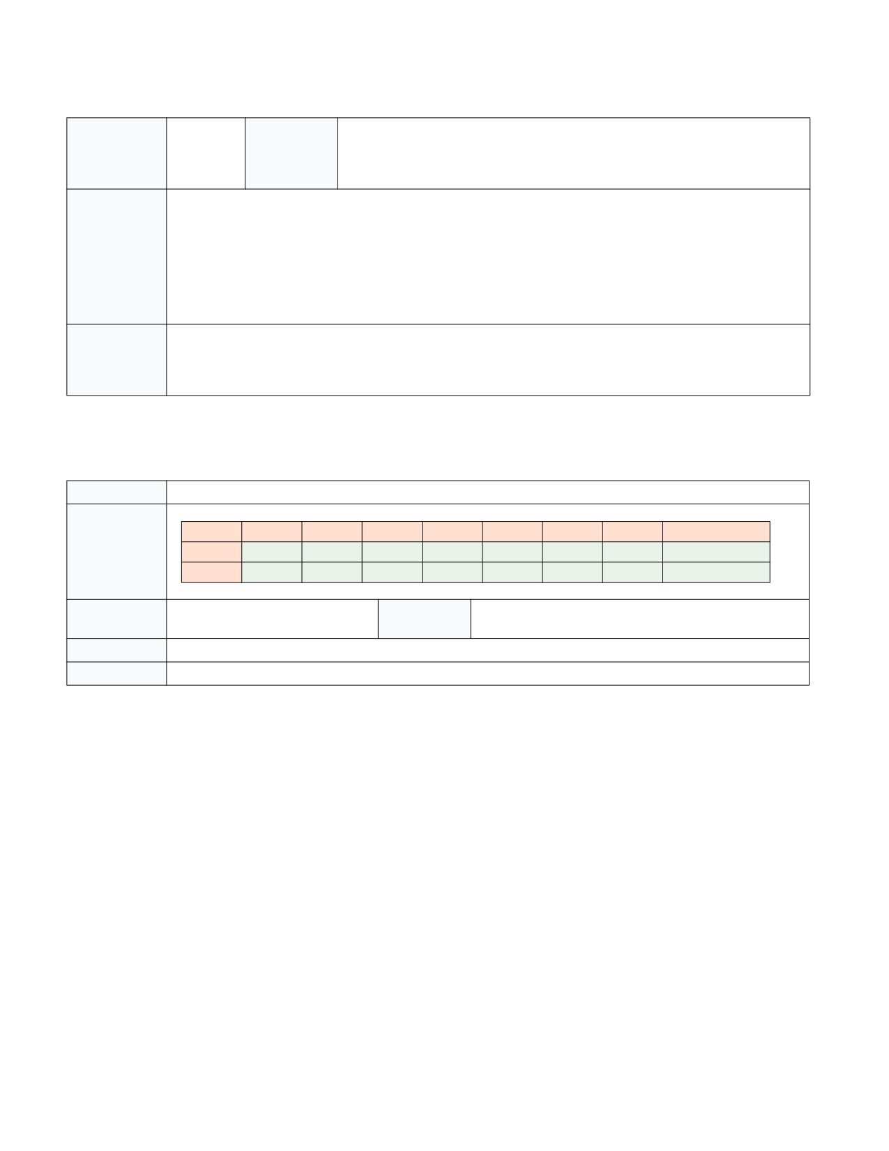
INTEL® PROCESSOR TRACE
Table 33-36. PSB Packet Definition (Contd.)
Dependencies
TriggerEn
Generation
Periodic, based on the number of output bytes generated while tracing. PSB is sent
Scenario
when IA32_RTIT_STATUS.PacketByteCnt=0, and each time it crosses the software
selected threshold after that. May be sent for other micro-architectural conditions
as well.
Description
PSB is a unique pattern in the packet output log, and hence serves as a sync point for the decoder. It is a pattern
that the decoder can search for in order to get aligned on packet boundaries. This packet is periodic, based on the
number of output bytes, as indicated by IA32_RTIT_STATUS.PacketByteCnt. The period is chosen by software, via
IA32_RTIT_CTL.PSBFreq (see Section 33.2.8.2). Note, however, that the PSB period is not precise, it simply reflects
the average number of output bytes that should pass between PSBs. The processor will make a best effort to
insert PSB as quickly after the selected threshold is reached as possible. The processor also may send extra
PSB packets for some micro-architectural conditions.
PSB also serves as the leading packet for a set of “status-only” packets collectively known as PSB+ (Section 33.3.7).
Application
When a PSB is seen, the decoder should interpret all following packets as “status only”, until either a PSBEND or
OVF packet is encountered. “Status only” implies that the binding and ordering rules to which these packets nor-
mally adhere are ignored, and the state they carry can instead be applied to the IP payload in the FUP packet that is
included.
33.4.2.18 PSBEND Packet
Table 33-37. PSBEND Packet Definition
Name
PSBEND Packet
Packet Format
7
6
5
4
3
2
1
0
0
0
0
0
0
0
0
1
0
1
0
0
1
0
0
0
1
1
Dependencies
TriggerEn
Generation
Always follows PSB packet, separated by PSB+ packets
Scenario
Description
PSBEND is simply a terminator for the series of “status only” (PSB+) packets that follow PSB (Section 33.3.7).
Application
When a PSBEND packet is seen, the decoder should cease to treat packets as “status only”.
Vol. 3C
33-57
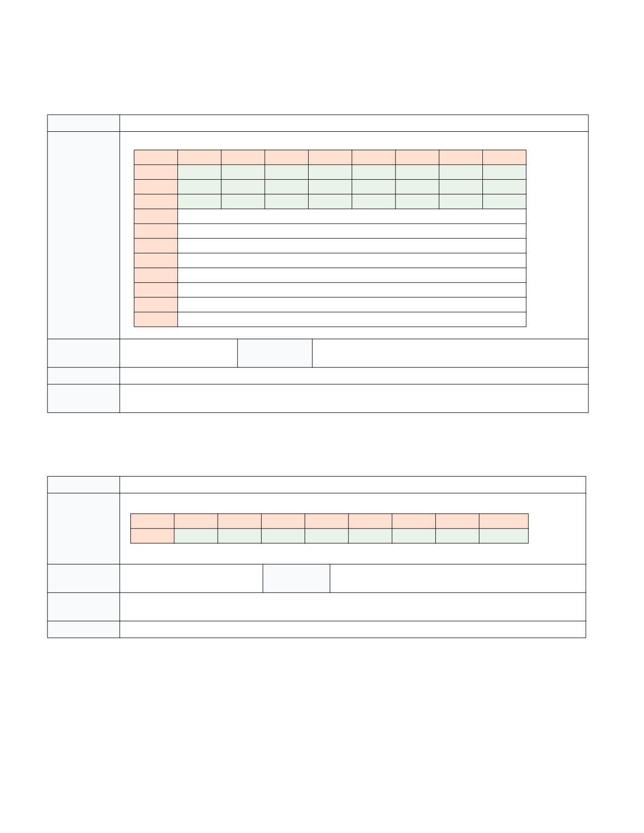
INTEL® PROCESSOR TRACE
33.4.2.19 Maintenance (MNT) Packet
Table 33-38. MNT Packet Definition
Name
Maintenance (MNT) Packet
Packet Format
7
6
5
4
3
2
1
0
0
0
0
0
0
0
0
1
0
1
1
1
0
0
0
0
1
1
2
1
0
0
0
1
0
0
0
3
Payload[7:0]
4
Payload[15:8]
5
Payload[23:16]
6
Payload[31:24]
7
Payload[39:32]
8
Payload[47:40]
9
Payload[55:48]
10
Payload[63:56]
Dependencies
TriggerEn
Generation
Implementation specific.
Scenario
Description
This packet is generated by hardware, the payload meaning is model-specific.
Application
Unless a decoder has been extended for a particular family/model/stepping to interpret MNT packet payloads, this
packet should simply be ignored. It does not bind to any IP.
33.4.2.20 PAD Packet
Table 33-39. PAD Packet Definition
Name
PAD Packet
Packet Format
7
6
5
4
3
2
1
0
0
0
0
0
0
0
0
0
0
Dependencies
TriggerEn
Generation
Implementation specific
Scenario
Description
PAD is simply a NOP packet. Processor implementations may choose to add pad packets to improve packet align-
ment or for implementation-specific reasons.
Application
Ignore PAD packets.
33-58
Vol. 3C

INTEL® PROCESSOR TRACE
33.4.2.21 PTWRITE (PTW) Packet
Table 33-40. PTW Packet Definition
Name
PTW Packet
Packet Format
7
6
5
4
3
2
1
0
0
0
0
0
0
0
0
1
0
1
IP
PayloadBytes
1
0
0
1
0
2
Payload[7:0]
3
Payload[15:8]
4
Payload[23:16]
5
Payload[31:24]
6
Payload[39:32]
7
Payload[47:40]
8
Payload[55:48]
9
Payload[63:56]
The PayloadBytes field indicates the number of bytes of payload that follow the header bytes. Encodings are as fol-
lows:
PayloadBytes
Bytes of Payload
‘00
4
‘01
8
‘10
Reserved
‘11
Reserved
IP bit indicates if a FUP, whose payload will be the IP of the PTWRITE instruction, will follow.
Dependencies
TriggerEn && ContextEn &&
Generation
PTWRITE Instruction
FilterEn && PTWEn
Scenario
Description
Contains the value held in the PTWRITE operand.
This packet is CYC-eligible, and hence will generate a CYC packet if IA32_RTIT_CTL.CYCEn=1 and any CYC Threshold
has been reached.
Application
Binds to the associated PTWRITE instruction. The IP of the PTWRITE will be provided by a following FUP, when
PTW.IP=1.
Vol. 3C
33-59

INTEL® PROCESSOR TRACE
33.4.2.22 Execution Stop (EXSTOP) Packet
Table 33-41. EXSTOP Packet Definition
Name
EXSTOP Packet
Packet Format
7
6
5
4
3
2
1
0
0
0
0
0
0
0
0
1
0
1
IP
1
1
0
0
0
1
0
IP bit indicates if a FUP will follow.
Dependencies
TriggerEn && PwrEvtEn
Generation
C-state entry, P-state change, or other processor clock power-
Scenario
down. Includes :
• Entry to C-state deeper than C0.0
• TM1/2
• STPCLK#
• Frequency change due to IA32_CLOCK_MODULATION, Turbo
Description
This packet indicates that software execution has stopped due to processor clock powerdown. Later packets will
indicate when execution resumes.
If EXSTOP is generated while ContextEn is set, the IP bit will be set, and EXSTOP will be followed by a FUP packet
containing the IP at which execution stopped. More precisely, this will be the IP of the oldest instruction that has
not yet completed.
This packet is CYC-eligible, and hence will generate a CYC packet if IA32_RTIT_CTL.CYCEn=1 and any CYC Threshold
has been reached.
Application
If a FUP follows EXSTOP (hence IP bit set), the EXSTOP can be bound to the FUP IP. Otherwise the IP is not known.
Time of powerdown can be inferred from the preceding CYC, if CYCEn=1. Combined with the TSC at the time of
wake (if TSCEn=1), this can be used to determine the duration of the powerdown.
33-60
Vol. 3C

INTEL® PROCESSOR TRACE
33.4.2.23 MWAIT Packet
Table 33-42. MWAIT Packet Definition
Name
MWAIT Packet
Packet Format
7
6
5
4
3
2
1
0
0
0
0
0
0
0
0
1
0
1
1
1
0
0
0
0
1
0
2
MWAIT Hints[7:0]
3
Reserved
4
Reserved
5
Reserved
6
Reserved
EXT[1:0]
7
Reserved
8
Reserved
9
Reserved
Dependencies
TriggerEn && PwrEvtEn &&
Generation
MWAIT, UMWAIT, or TPAUSE instructions, or I/O redirection to
ContextEn
Scenario
MWAIT, that complete without fault or VMexit.
Description
Indicates that an MWAIT operation to C-state deeper than C0.0 completed. The MWAIT hints and extensions passed
in by software are exposed in the payload. For UMWAIT and TPAUSE, the EXT field holds the input register value
that determines the optimized state requested.
For entry to some highly optimized C0 sub-C-states, such as C0.1, no MWAIT packet is generated.
This packet is CYC-eligible, and hence will generate a CYC packet if IA32_RTIT_CTL.CYCEn=1 and any CYC Threshold
has been reached.
Application
The binding for the upcoming EXSTOP packet also applies to the MWAIT packet. See Section 33.4.2.22.
Vol. 3C
33-61
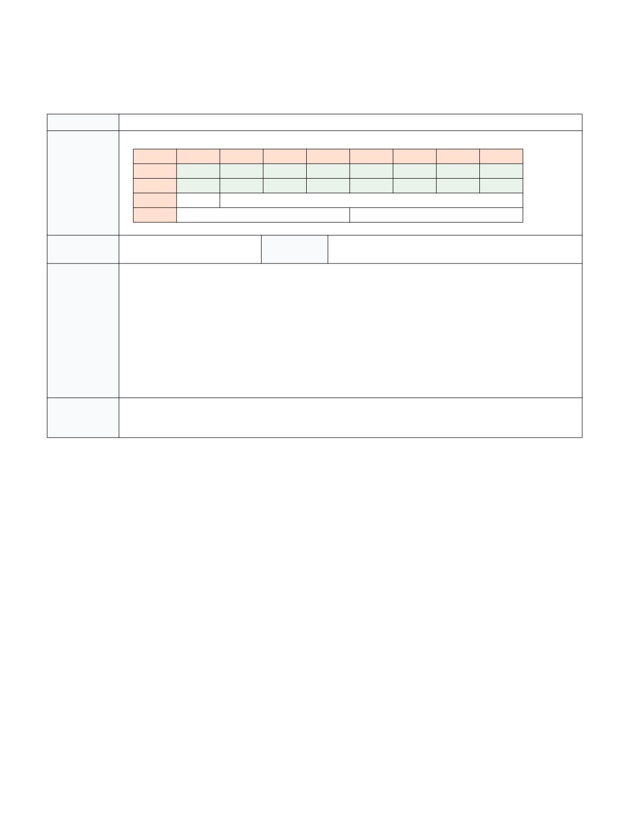
INTEL® PROCESSOR TRACE
33.4.2.24 Power Entry (PWRE) Packet
Table 33-43. PWRE Packet Definition
Name
PWRE Packet
Packet Format
7
6
5
4
3
2
1
0
0
0
0
0
0
0
0
1
0
1
0
0
1
0
0
0
1
0
2
HW
Reserved
3
Resolved Thread C-State
Resolved Thread Sub C-State
Dependencies
TriggerEn && PwrEvtEn
Generation
Transition to a C-state deeper than C0.0.
Scenario
Description
Indicates processor entry to the resolved thread C-state and sub C-state indicated. The processor will remain in this
C-state until either another PWRE indicates the processor has moved to a C-state deeper than C0.0, or a PWRX
packet indicates a return to C0.0.
For entry to some highly optimized C0 sub-C-states, such as C0.1, no PWRE packet is generated.
Note that some CPUs may allow MWAIT to request a deeper C-state than is supported by the core. These deeper C-
states may have platform-level implications that differentiate them. However, the PWRE packet will provide only
the resolved thread C-state, which will not exceed that supported by the core.
If the C-state entry was initiated by hardware, rather than a direct software request (such as MWAIT, UMWAIT,
TPAUSE, HLT, or shutdown), the HW bit will be set to indicate this. Hardware Duty Cycling (see Section 15.5, “Hard-
ware Duty Cycling (HDC),” in the Intel® 64 and IA-32 Architectures Software Developer’s Manual, Volume 3B) is an
example of such a case.
Application
When transitioning from C0.0 to a deeper C-state, the PWRE packet will be followed by an EXSTOP. If that EXSTOP
packet has the IP bit set, then the following FUP will provide the IP at which the C-state entry occurred. Subsequent
PWRE packets generated before the next PWRX should bind to the same IP.
33-62
Vol. 3C

INTEL® PROCESSOR TRACE
33.4.2.25 Power Exit (PWRX) Packet
Table 33-44. PWRX Packet Definition
Name
PWRX Packet
Packet Format
7
6
5
4
3
2
1
0
0
0
0
0
0
0
0
1
0
1
1
0
1
0
0
0
1
0
2
Last Core C-State
Deepest Core C-State
3
Reserved
Wake Reason
4
Reserved
5
Reserved
6
Reserved
Dependencies
TriggerEn && PwrEvtEn
Generation
Transition from a C-state deeper than C0.0 to C0.
Scenario
Description
Indicates processor return to thread C0 from a C-state deeper than C0.0.
For return from some highly optimized C0 sub-C-states, such as C0.1, no PWRX packet is generated.
The Last Core C-State field provides the MWAIT encoding for the core C-state at the time of the wake. The Deepest
Core C-State provides the MWAIT encoding for the deepest core C-state achieved during the sleep session, or since
leaving thread C0. MWAIT encodings for C-states can be found in Table 4-11 in the Intel® 64 and IA-32 Architec-
tures Software Developer’s Manual, Volume 2B. Note that these values reflect only the core C-state, and hence will
not exceed the maximum supported core C-state, even if deeper C-states can be requested.
The Wake Reason field is one-hot, encoded as follows:
Bit
Field
Meaning
0
Interrupt
Wake due to external interrupt received.
1
Timer Deadline
Wake due to timer expiration, such as
UMWAIT/TPAUSE TSC-quanta.
2
Store to Monitored Address
Wake due to store to monitored address.
3
HW Wake
Wake due to hardware autonomous condition,
such as HDC.
Application
PWRX will always apply to the same IP as the PWRE. The time of wake can be discerned from (optional) timing pack-
ets that precede PWRX.
Vol. 3C
33-63

INTEL® PROCESSOR TRACE
33.4.2.26 Block Begin Packet (BBP)
Table 33-45. Block Begin Packet Definition
Name
BBP
Packet Format
7
6
5
4
3
2
1
0
0
0
0
0
0
0
0
1
0
1
0
1
1
0
0
0
1
1
2
SZ
Reserved
Type[4:0]
Dependencies
TriggerEn
Generation
PEBS event, if IA32_PEBS_ENABLE.OUTPUT=1.
Scenario
Description
This packet indicates the beginning of a block of packets which are collectively tied to a single event or instruction.
The size of the block item payloads within this block is provided by the Size (SZ) bit:
SZ=0: 8-byte block items
SZ=1: 4-byte block items
The meaning of the BIP payloads is provided by the Type field:
BBP.Type
Block name
0x00
Reserved
0x01
General-Purpose Registers
0x02..0x03
Reserved
0x04
PEBS Basic
0x05
PEBS Memory
0x06..0x07
Reserved
0x08
LBR Block 0
0x09
LBR Block 1
0x0A
LBR Block 2
0x0B..0x0F
Reserved
0x10
XMM Registers
0x11..0x1F
Reserved
Application
A BBP will always be followed by a Block End Packet (BEP), and when the block is generated while ContextEn=1
that BEP will have IP=1 and be followed by a FUP that provides the IP to which the block should be bound. Note
that, in addition to BEP, a block can be terminated by a BBP (indicating the start of a new block) or an OVF packet.
33-64
Vol. 3C
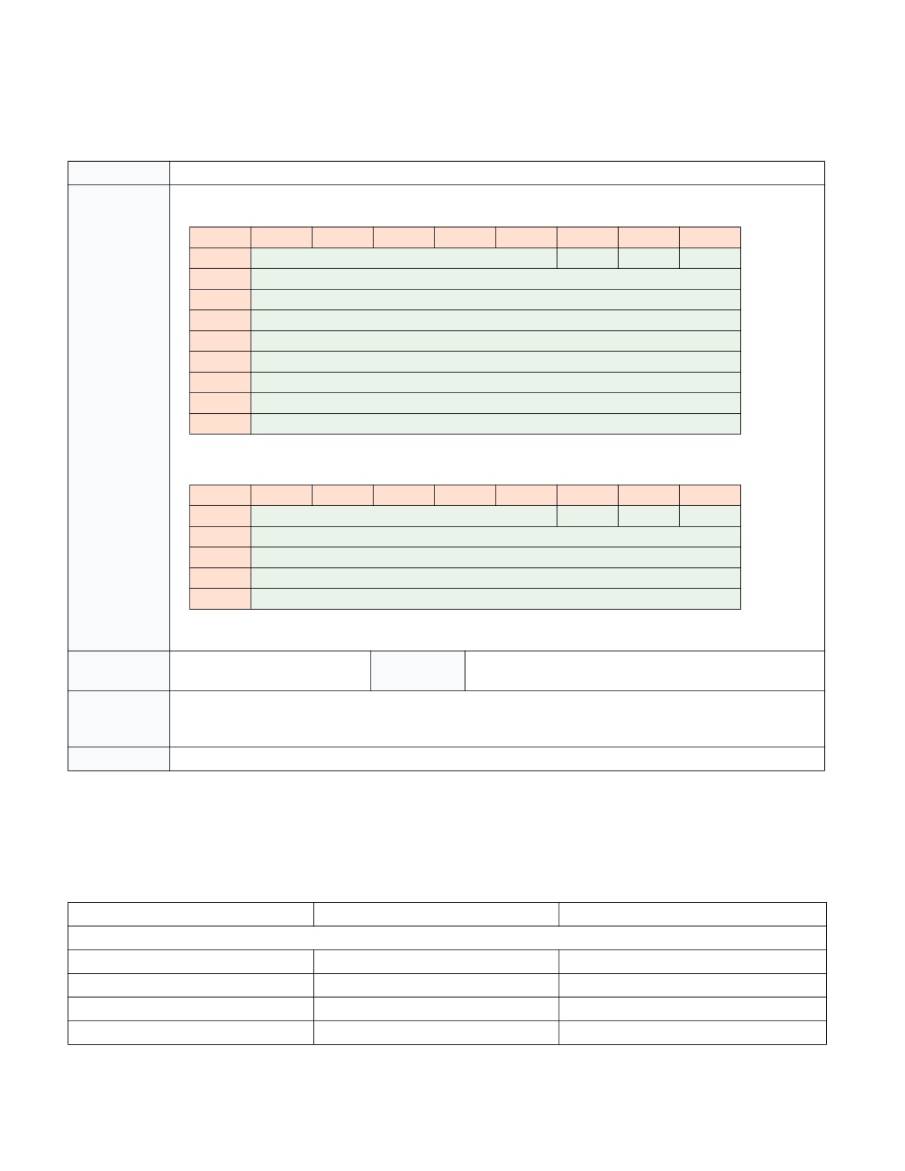
INTEL® PROCESSOR TRACE
33.4.2.27 Block Item Packet (BIP)
Table 33-46. Block Item Packet Definition
Name
BIP
Packet Format
If the preceding BBP.SZ=0:
7
6
5
4
3
2
1
0
0
ID[5:0]
1
0
0
1
Payload[7:0]
2
Payload[15:8]
3
Payload[23:16]
4
Payload[31:24]
5
Payload[39:32]
6
Payload[47:40]
7
Payload[55:48]
8
Payload[63:56]
If the preceding BBP.SZ=1:
7
6
5
4
3
2
1
0
0
ID[5:0]
1
0
0
1
Payload[7:0]
2
Payload[15:8]
3
Payload[23:16]
4
Payload[31:24]
Dependencies
TriggerEn
Generation
See BBP.
Scenario
Description
The size of the BIP payload is determined by the Size field in the preceding BBP packet.
The BIP header provides the ID value that, when combined with the Type field from the preceding BBP, uniquely
identifies the state value held in the BIP payload. See Table 33-47 below for the complete list.
Application
See BBP.
BIP State Value Encodings
The table below provides the encoding values for all defined block items. State items that are larger than 8 bytes,
such as XMM register values, are broken into multiple 8-byte components. BIP packets with Size=1 (4 byte
payload) will provide only the lower 4 bytes of the associated state value.
Table 33-47. BIP Encodings
BBP.Type
BIP.ID
State Value
General-Purpose Registers
0x01
0x00
R/EFLAGS
0x01
0x01
R/EIP
0x01
0x02
R/EAX
0x01
0x03
R/ECX
Vol. 3C
33-65

INTEL® PROCESSOR TRACE
Table 33-47. BIP Encodings (Contd.)
BBP.Type
BIP.ID
State Value
0x01
0x04
R/EDX
0x01
0x05
R/EBX
0x01
0x06
R/ESP
0x01
0x07
R/EBP
0x01
0x08
R/ESI
0x01
0x09
R/EDI
0x01
0x0A
R8
0x01
0x0B
R9
0x01
0x0C
R10
0x01
0x0D
R11
0x01
0x0E
R12
0x01
0x0F
R13
0x01
0x10
R14
0x01
0x11
R15
PEBS Basic Info (Section 20.9.2.2.1)
0x04
0x00
Instruction Pointer
0x04
0x01
Applicable Counters
0x04
0x02
Timestamp
PEBS Memory Info (Section 20.9.2.2.2)
0x05
0x00
MemAccessAddress
0x05
0x01
MemAuxInfo
0x05
0x02
MemAccessLatency
0x05
0x03
TSXAuxInfo
LBR_0
0x08
0x00
LBR[TOS-0]_FROM_IP
0x08
0x01
LBR[TOS-0]_TO_IP
0x08
0x02
LBR[TOS-0]_INFO
0x08
0x03
LBR[TOS-1]_FROM_IP
0x08
0x04
LBR[TOS-1]_TO_IP
0x08
0x05
LBR[TOS-1]_INFO
0x08
0x06
LBR[TOS-2]_FROM_IP
0x08
0x07
LBR[TOS-2]_TO_IP
0x08
0x08
LBR[TOS-2]_INFO
0x08
0x09
LBR[TOS-3]_FROM_IP
0x08
0x0A
LBR[TOS-3]_TO_IP
0x08
0x0B
LBR[TOS-3]_INFO
0x08
0x0C
LBR[TOS-4]_FROM_IP
0x08
0x0D
LBR[TOS-4]_TO_IP
33-66
Vol. 3C

INTEL® PROCESSOR TRACE
Table 33-47. BIP Encodings (Contd.)
BBP.Type
BIP.ID
State Value
0x08
0x0E
LBR[TOS-4]_INFO
0x08
0x0F
LBR[TOS-5]_FROM_IP
0x08
0x10
LBR[TOS-5]_TO_IP
0x08
0x11
LBR[TOS-5]_INFO
0x08
0x12
LBR[TOS-6]_FROM_IP
0x08
0x13
LBR[TOS-6]_TO_IP
0x08
0x14
LBR[TOS-6]_INFO
0x08
0x15
LBR[TOS-7]_FROM_IP
0x08
0x16
LBR[TOS-7]_TO_IP
0x08
0x17
LBR[TOS-7]_INFO
0x08
0x18
LBR[TOS-8]_FROM_IP
0x08
0x19
LBR[TOS-8]_TO_IP
0x08
0x1A
LBR[TOS-8]_INFO
0x08
0x1B
LBR[TOS-9]_FROM_IP
0x08
0x1C
LBR[TOS-9]_TO_IP
0x08
0x1D
LBR[TOS-9]_INFO
0x08
0x1E
LBR[TOS-10]_FROM_IP
0x08
0x1F
LBR[TOS-10]_TO_IP
LBR_1
0x09
0x00
LBR[TOS-10]_INFO
0x09
0x01
LBR[TOS-11]_FROM_IP
0x09
0x02
LBR[TOS-11]_TO_IP
0x09
0x03
LBR[TOS-11]_INFO
0x09
0x04
LBR[TOS-12]_FROM_IP
0x09
0x05
LBR[TOS-12]_TO_IP
0x09
0x06
LBR[TOS-12]_INFO
0x09
0x07
LBR[TOS-13]_FROM_IP
0x09
0x08
LBR[TOS-13]_TO_IP
0x09
0x09
LBR[TOS-13]_INFO
0x09
0x0A
LBR[TOS-14]_FROM_IP
0x09
0x0B
LBR[TOS-14]_TO_IP
0x09
0x0C
LBR[TOS-14]_INFO
0x09
0x0D
LBR[TOS-15]_FROM_IP
0x09
0x0E
LBR[TOS-15]_TO_IP
0x09
0x0F
LBR[TOS-15]_INFO
0x09
0x10
LBR[TOS-16]_FROM_IP
0x09
0x11
LBR[TOS-16]_TO_IP
0x09
0x12
LBR[TOS-16]_INFO
Vol. 3C
33-67

INTEL® PROCESSOR TRACE
Table 33-47. BIP Encodings (Contd.)
BBP.Type
BIP.ID
State Value
0x09
0x13
LBR[TOS-17]_FROM_IP
0x09
0x14
LBR[TOS-17]_TO_IP
0x09
0x15
LBR[TOS-17]_INFO
0x09
0x16
LBR[TOS-18]_FROM_IP
0x09
0x17
LBR[TOS-18]_TO_IP
0x09
0x18
LBR[TOS-18]_INFO
0x09
0x19
LBR[TOS-19]_FROM_IP
0x09
0x1A
LBR[TOS-19]_TO_IP
0x09
0x1B
LBR[TOS-19]_INFO
0x09
0x1C
LBR[TOS-20]_FROM_IP
0x09
0x1D
LBR[TOS-20]_TO_IP
0x09
0x1E
LBR[TOS-20]_INFO
0x09
0x1F
LBR[TOS-21]_FROM_IP
LBR_2
0x0A
0x00
LBR[TOS-21]_TO_IP
0x0A
0x01
LBR[TOS-21]_INFO
0x0A
0x02
LBR[TOS-22]_FROM_IP
0x0A
0x03
LBR[TOS-22]_TO_IP
0x0A
0x04
LBR[TOS-22]_INFO
0x0A
0x05
LBR[TOS-23]_FROM_IP
0x0A
0x06
LBR[TOS-23]_TO_IP
0x0A
0x07
LBR[TOS-23]_INFO
0x0A
0x08
LBR[TOS-24]_FROM_IP
0x0A
0x09
LBR[TOS-24]_TO_IP
0x0A
0x0A
LBR[TOS-24]_INFO
0x0A
0x0B
LBR[TOS-25]_FROM_IP
0x0A
0x0C
LBR[TOS-25]_TO_IP
0x0A
0x0D
LBR[TOS-25]_INFO
0x0A
0x0E
LBR[TOS-26]_FROM_IP
0x0A
0x0F
LBR[TOS-26]_TO_IP
0x0A
0x10
LBR[TOS-26]_INFO
0x0A
0x11
LBR[TOS-27]_FROM_IP
0x0A
0x12
LBR[TOS-27]_TO_IP
0x0A
0x13
LBR[TOS-27]_INFO
0x0A
0x14
LBR[TOS-28]_FROM_IP
0x0A
0x15
LBR[TOS-28]_TO_IP
0x0A
0x16
LBR[TOS-28]_INFO
0x0A
0x17
LBR[TOS-29]_FROM_IP
33-68
Vol. 3C