Intel 64 and IA-32 Architectures. Software Developer’s Manual (Collection, 2023) - page 36
INSTRUCTION SET REFERENCE, M-U
VPSUBD (VEX.128 Encoded Version)
DEST[31:0] := SRC1[31:0]-SRC2[31:0]
DEST[63:32] := SRC1[63:32]-SRC2[63:32]
DEST[95:64] := SRC1[95:64]-SRC2[95:64]
DEST[127:96] := SRC1[127:96]-SRC2[127:96]
DEST[MAXVL-1:128] := 0
PSUBD (128-bit Legacy SSE Version)
DEST[31:0] := DEST[31:0]-SRC[31:0]
DEST[63:32] := DEST[63:32]-SRC[63:32]
DEST[95:64] := DEST[95:64]-SRC[95:64]
DEST[127:96] := DEST[127:96]-SRC[127:96]
DEST[MAXVL-1:128] (Unmodified)
Intel C/C++ Compiler Intrinsic Equivalents
VPSUBB __m512i _mm512_sub_epi8(__m512i a, __m512i b);
VPSUBB __m512i _mm512_mask_sub_epi8(__m512i s, __mmask64 k, __m512i a, __m512i b);
VPSUBB __m512i _mm512_maskz_sub_epi8( __mmask64 k, __m512i a, __m512i b);
VPSUBB __m256i _mm256_mask_sub_epi8(__m256i s, __mmask32 k, __m256i a, __m256i b);
VPSUBB __m256i _mm256_maskz_sub_epi8( __mmask32 k, __m256i a, __m256i b);
VPSUBB __m128i _mm_mask_sub_epi8(__m128i s, __mmask16 k, __m128i a, __m128i b);
VPSUBB __m128i _mm_maskz_sub_epi8( __mmask16 k, __m128i a, __m128i b);
VPSUBW __m512i _mm512_sub_epi16(__m512i a, __m512i b);
VPSUBW __m512i _mm512_mask_sub_epi16(__m512i s, __mmask32 k, __m512i a, __m512i b);
VPSUBW __m512i _mm512_maskz_sub_epi16( __mmask32 k, __m512i a, __m512i b);
VPSUBW __m256i _mm256_mask_sub_epi16(__m256i s, __mmask16 k, __m256i a, __m256i b);
VPSUBW __m256i _mm256_maskz_sub_epi16( __mmask16 k, __m256i a, __m256i b);
VPSUBW __m128i _mm_mask_sub_epi16(__m128i s, __mmask8 k, __m128i a, __m128i b);
VPSUBW __m128i _mm_maskz_sub_epi16( __mmask8 k, __m128i a, __m128i b);
VPSUBD __m512i _mm512_sub_epi32(__m512i a, __m512i b);
VPSUBD __m512i _mm512_mask_sub_epi32(__m512i s, __mmask16 k, __m512i a, __m512i b);
VPSUBD __m512i _mm512_maskz_sub_epi32( __mmask16 k, __m512i a, __m512i b);
VPSUBD __m256i _mm256_mask_sub_epi32(__m256i s, __mmask8 k, __m256i a, __m256i b);
VPSUBD __m256i _mm256_maskz_sub_epi32( __mmask8 k, __m256i a, __m256i b);
VPSUBD __m128i _mm_mask_sub_epi32(__m128i s, __mmask8 k, __m128i a, __m128i b);
VPSUBD __m128i _mm_maskz_sub_epi32( __mmask8 k, __m128i a, __m128i b);
PSUBB __m64 _mm_sub_pi8(__m64 m1, __m64 m2)
(V)PSUBB __m128i _mm_sub_epi8 ( __m128i a, __m128i b)
VPSUBB __m256i _mm256_sub_epi8 ( __m256i a, __m256i b)
PSUBW __m64 _mm_sub_pi16(__m64 m1, __m64 m2)
(V)PSUBW __m128i _mm_sub_epi16 ( __m128i a, __m128i b)
VPSUBW __m256i _mm256_sub_epi16 ( __m256i a, __m256i b)
PSUBD __m64 _mm_sub_pi32(__m64 m1, __m64 m2)
(V)PSUBD __m128i _mm_sub_epi32 ( __m128i a, __m128i b)
VPSUBD __m256i _mm256_sub_epi32 ( __m256i a, __m256i b)
Flags Affected
None.
Numeric Exceptions
None.
PSUBB/PSUBW/PSUBD-Subtract Packed Integers
Vol. 2B
4-479
INSTRUCTION SET REFERENCE, M-U
Other Exceptions
Non-EVEX-encoded instruction, see Table 2-21, “Type 4 Class Exception Conditions.”
EVEX-encoded VPSUBD, see Table 2-49, “Type E4 Class Exception Conditions.”
EVEX-encoded VPSUBB/W, see Exceptions Type E4.nb in Table 2-49, “Type E4 Class Exception Conditions.”
4-480
Vol. 2B
PSUBB/PSUBW/PSUBD-Subtract Packed Integers

INSTRUCTION SET REFERENCE, M-U
PSUBQ-Subtract Packed Quadword Integers
Opcode/
Op/
64/32 bit
CPUID
Description
Instruction
En
Mode
Feature
Support
Flag
NP 0F FB /r1
A
V/V
SSE2
Subtract quadword integer in mm1 from mm2
/m64.
PSUBQ mm1, mm2/m64
66 0F FB /r
A
V/V
SSE2
Subtract packed quadword integers in xmm1
from xmm2 /m128.
PSUBQ xmm1, xmm2/m128
VEX.128.66.0F.WIG FB/r
B
V/V
AVX
Subtract packed quadword integers in
VPSUBQ xmm1, xmm2, xmm3/m128
xmm3/m128 from xmm2.
VEX.256.66.0F.WIG FB /r
B
V/V
AVX2
Subtract packed quadword integers in
ymm3/m256 from ymm2.
VPSUBQ ymm1, ymm2, ymm3/m256
EVEX.128.66.0F.W1 FB /r
C
V/V
AVX512VL
Subtract packed quadword integers in
VPSUBQ xmm1 {k1}{z}, xmm2, xmm3/m128/m64bcst
AVX512F
xmm3/m128/m64bcst from xmm2 and store
in xmm1 using writemask k1.
EVEX.256.66.0F.W1 FB /r
C
V/V
AVX512VL
Subtract packed quadword integers in
VPSUBQ ymm1 {k1}{z}, ymm2, ymm3/m256/m64bcst
AVX512F
ymm3/m256/m64bcst from ymm2 and store
in ymm1 using writemask k1.
EVEX.512.66.0F.W1 FB/r
C
V/V
AVX512F
Subtract packed quadword integers in
VPSUBQ zmm1 {k1}{z}, zmm2, zmm3/m512/m64bcst
zmm3/m512/m64bcst from zmm2 and store
in zmm1 using writemask k1.
NOTES:
1. See note in Section 2.5, “Intel® AVX and Intel® SSE Instruction Exception Classification,” in the Intel® 64 and IA-32 Architectures Soft-
ware Developer’s Manual, Volume 2A, and Section 23.25.3, “Exception Conditions of Legacy SIMD Instructions Operating on MMX Reg-
isters,” in the Intel® 64 and IA-32 Architectures Software Developer’s Manual, Volume 3B.
Instruction Operand Encoding
Op/En
Tuple Type
Operand 1
Operand 2
Operand 3
Operand 4
A
N/A
ModRM:reg (r, w)
ModRM:r/m (r)
N/A
N/A
B
N/A
ModRM:reg (w)
VEX.vvvv (r)
ModRM:r/m (r)
N/A
C
Full
ModRM:reg (w)
EVEX.vvvv (r)
ModRM:r/m (r)
N/A
Description
Subtracts the second operand (source operand) from the first operand (destination operand) and stores the result
in the destination operand. When packed quadword operands are used, a SIMD subtract is performed. When a
quadword result is too large to be represented in 64 bits (overflow), the result is wrapped around and the low 64
bits are written to the destination element (that is, the carry is ignored).
Note that the (V)PSUBQ instruction can operate on either unsigned or signed (two’s complement notation) inte-
gers; however, it does not set bits in the EFLAGS register to indicate overflow and/or a carry. To prevent undetected
overflow conditions, software must control the ranges of the values upon which it operates.
In 64-bit mode and not encoded with VEX/EVEX, using a REX prefix in the form of REX.R permits this instruction to
access additional registers (XMM8-XMM15).
Legacy SSE version 64-bit operand: The source operand can be a quadword integer stored in an MMX technology
register or a 64-bit memory location.
128-bit Legacy SSE version: The second source operand is an XMM register or a 128-bit memory location. The first
source operand and destination operands are XMM registers. Bits (MAXVL-1:128) of the corresponding YMM desti-
nation register remain unchanged.
PSUBQ-Subtract Packed Quadword Integers
Vol. 2B
4-481
INSTRUCTION SET REFERENCE, M-U
VEX.128 encoded version: The second source operand is an XMM register or a 128-bit memory location. The first
source operand and destination operands are XMM registers. Bits (MAXVL-1:128) of the destination YMM register
are zeroed.
VEX.256 encoded versions: The second source operand is an YMM register or an 256-bit memory location. The first
source operand and destination operands are YMM registers. Bits (MAXVL-1:256) of the corresponding ZMM
register are zeroed.
EVEX encoded VPSUBQ: The second source operand is a ZMM/YMM/XMM register, a 512/256/128-bit memory loca-
tion or a 512/256/128-bit vector broadcasted from a 32/64-bit memory location. The first source operand and
destination operands are ZMM/YMM/XMM registers. The destination is conditionally updated with writemask k1.
Operation
PSUBQ (With 64-Bit Operands)
DEST[63:0] := DEST[63:0] - SRC[63:0];
PSUBQ (With 128-Bit Operands)
DEST[63:0] := DEST[63:0] - SRC[63:0];
DEST[127:64] := DEST[127:64] - SRC[127:64];
VPSUBQ (VEX.128 Encoded Version)
DEST[63:0] := SRC1[63:0]-SRC2[63:0]
DEST[127:64] := SRC1[127:64]-SRC2[127:64]
DEST[MAXVL-1:128] := 0
VPSUBQ (VEX.256 Encoded Version)
DEST[63:0] := SRC1[63:0]-SRC2[63:0]
DEST[127:64] := SRC1[127:64]-SRC2[127:64]
DEST[191:128] := SRC1[191:128]-SRC2[191:128]
DEST[255:192] := SRC1[255:192]-SRC2[255:192]
DEST[MAXVL-1:256] := 0
VPSUBQ (EVEX Encoded Versions)
(KL, VL) = (2, 128), (4, 256), (8, 512)
FOR j := 0 TO KL-1
i := j * 64
IF k1[j] OR *no writemask* THEN
IF (EVEX.b = 1) AND (SRC2 *is memory*)
THEN DEST[i+63:i] := SRC1[i+63:i] - SRC2[63:0]
ELSE DEST[i+63:i] := SRC1[i+63:i] - SRC2[i+63:i]
FI;
ELSE
IF *merging-masking*
; merging-masking
THEN *DEST[i+63:i] remains unchanged*
ELSE *zeroing-masking*
; zeroing-masking
DEST[i+63:i] := 0
FI
FI;
ENDFOR;
DEST[MAXVL-1:VL] := 0
4-482
Vol. 2B
PSUBQ-Subtract Packed Quadword Integers
INSTRUCTION SET REFERENCE, M-U
Intel C/C++ Compiler Intrinsic Equivalents
VPSUBQ __m512i _mm512_sub_epi64(__m512i a, __m512i b);
VPSUBQ __m512i _mm512_mask_sub_epi64(__m512i s, __mmask8 k, __m512i a, __m512i b);
VPSUBQ __m512i _mm512_maskz_sub_epi64( __mmask8 k, __m512i a, __m512i b);
VPSUBQ __m256i _mm256_mask_sub_epi64(__m256i s, __mmask8 k, __m256i a, __m256i b);
VPSUBQ __m256i _mm256_maskz_sub_epi64( __mmask8 k, __m256i a, __m256i b);
VPSUBQ __m128i _mm_mask_sub_epi64(__m128i s, __mmask8 k, __m128i a, __m128i b);
VPSUBQ __m128i _mm_maskz_sub_epi64( __mmask8 k, __m128i a, __m128i b);
PSUBQ __m64 _mm_sub_si64(__m64 m1, __m64 m2)
(V)PSUBQ __m128i _mm_sub_epi64(__m128i m1, __m128i m2)
VPSUBQ __m256i _mm256_sub_epi64(__m256i m1, __m256i m2)
Flags Affected
None.
Numeric Exceptions
None.
Other Exceptions
Non-EVEX-encoded instruction, see Table 2-21, “Type 4 Class Exception Conditions.”
EVEX-encoded VPSUBQ, see Table 2-49, “Type E4 Class Exception Conditions.”
PSUBQ-Subtract Packed Quadword Integers
Vol. 2B
4-483

INSTRUCTION SET REFERENCE, M-U
PSUBSB/PSUBSW-Subtract Packed Signed Integers With Signed Saturation
Opcode/
Op/
64/32 bit
CPUID
Description
Instruction
En
Mode
Feature
Support
Flag
NP 0F E8 /r1
A
V/V
MMX
Subtract signed packed bytes in mm/m64 from
signed packed bytes in mm and saturate results.
PSUBSB mm, mm/m64
66 0F E8 /r
A
V/V
SSE2
Subtract packed signed byte integers in
xmm2/m128 from packed signed byte integers in
PSUBSB xmm1, xmm2/m128
xmm1 and saturate results.
NP 0F E9 /r1
A
V/V
MMX
Subtract signed packed words in mm/m64 from
signed packed words in mm and saturate results.
PSUBSW mm, mm/m64
66 0F E9 /r
A
V/V
SSE2
Subtract packed signed word integers in
xmm2/m128 from packed signed word integers in
PSUBSW xmm1, xmm2/m128
xmm1 and saturate results.
VEX.128.66.0F.WIG E8 /r
B
V/V
AVX
Subtract packed signed byte integers in
xmm3/m128 from packed signed byte integers in
VPSUBSB xmm1, xmm2, xmm3/m128
xmm2 and saturate results.
VEX.128.66.0F.WIG E9 /r
B
V/V
AVX
Subtract packed signed word integers in
xmm3/m128 from packed signed word integers in
VPSUBSW xmm1, xmm2, xmm3/m128
xmm2 and saturate results.
VEX.256.66.0F.WIG E8 /r
B
V/V
AVX2
Subtract packed signed byte integers in
ymm3/m256 from packed signed byte integers in
VPSUBSB ymm1, ymm2, ymm3/m256
ymm2 and saturate results.
VEX.256.66.0F.WIG E9 /r
B
V/V
AVX2
Subtract packed signed word integers in
ymm3/m256 from packed signed word integers in
VPSUBSW ymm1, ymm2, ymm3/m256
ymm2 and saturate results.
EVEX.128.66.0F.WIG E8 /r
C
V/V
AVX512VL
Subtract packed signed byte integers in
VPSUBSB xmm1 {k1}{z}, xmm2, xmm3/m128
AVX512BW
xmm3/m128 from packed signed byte integers in
xmm2 and saturate results and store in xmm1
using writemask k1.
EVEX.256.66.0F.WIG E8 /r
C
V/V
AVX512VL
Subtract packed signed byte integers in
VPSUBSB ymm1 {k1}{z}, ymm2, ymm3/m256
AVX512BW
ymm3/m256 from packed signed byte integers in
ymm2 and saturate results and store in ymm1
using writemask k1.
EVEX.512.66.0F.WIG E8 /r
C
V/V
AVX512BW
Subtract packed signed byte integers in
VPSUBSB zmm1 {k1}{z}, zmm2, zmm3/m512
zmm3/m512 from packed signed byte integers in
zmm2 and saturate results and store in zmm1 using
writemask k1.
EVEX.128.66.0F.WIG E9 /r
C
V/V
AVX512VL
Subtract packed signed word integers in
VPSUBSW xmm1 {k1}{z}, xmm2, xmm3/m128
AVX512BW
xmm3/m128 from packed signed word integers in
xmm2 and saturate results and store in xmm1
using writemask k1.
EVEX.256.66.0F.WIG E9 /r
C
V/V
AVX512VL
Subtract packed signed word integers in
VPSUBSW ymm1 {k1}{z}, ymm2, ymm3/m256
AVX512BW
ymm3/m256 from packed signed word integers in
ymm2 and saturate results and store in ymm1
using writemask k1.
EVEX.512.66.0F.WIG E9 /r
C
V/V
AVX512BW
Subtract packed signed word integers in
VPSUBSW zmm1 {k1}{z}, zmm2, zmm3/m512
zmm3/m512 from packed signed word integers in
zmm2 and saturate results and store in zmm1 using
writemask k1.
4-484
Vol. 2B
PSUBSB/PSUBSW-Subtract Packed Signed Integers With Signed Saturation
INSTRUCTION SET REFERENCE, M-U
NOTES:
1. See note in Section 2.5, “Intel® AVX and Intel® SSE Instruction Exception Classification,” in the Intel® 64 and IA-32 Architectures Soft-
ware Developer’s Manual, Volume 2A, and Section 23.25.3, “Exception Conditions of Legacy SIMD Instructions Operating on MMX
Registers,” in the Intel® 64 and IA-32 Architectures Software Developer’s Manual, Volume 3B.
Instruction Operand Encoding
Op/En
Tuple Type
Operand 1
Operand 2
Operand 3
Operand 4
A
N/A
ModRM:reg (r, w)
ModRM:r/m (r)
N/A
N/A
B
N/A
ModRM:reg (w)
VEX.vvvv (r)
ModRM:r/m (r)
N/A
C
Full Mem
ModRM:reg (w)
EVEX.vvvv (r)
ModRM:r/m (r)
N/A
Description
Performs a SIMD subtract of the packed signed integers of the source operand (second operand) from the packed
signed integers of the destination operand (first operand), and stores the packed integer results in the destination
operand. See Figure 9-4 in the Intel® 64 and IA-32 Architectures Software Developer’s Manual, Volume 1, for an
illustration of a SIMD operation. Overflow is handled with signed saturation, as described in the following para-
graphs.
The (V)PSUBSB instruction subtracts packed signed byte integers. When an individual byte result is beyond the
range of a signed byte integer (that is, greater than 7FH or less than 80H), the saturated value of 7FH or 80H,
respectively, is written to the destination operand.
The (V)PSUBSW instruction subtracts packed signed word integers. When an individual word result is beyond the
range of a signed word integer (that is, greater than 7FFFH or less than 8000H), the saturated value of 7FFFH or
8000H, respectively, is written to the destination operand.
In 64-bit mode and not encoded with VEX/EVEX, using a REX prefix in the form of REX.R permits this instruction to
access additional registers (XMM8-XMM15).
Legacy SSE version 64-bit operand: The destination operand must be an MMX technology register and the source
operand can be either an MMX technology register or a 64-bit memory location.
128-bit Legacy SSE version: The second source operand is an XMM register or a 128-bit memory location. The first
source operand and destination operands are XMM registers. Bits (MAXVL-1:128) of the corresponding YMM desti-
nation register remain unchanged.
VEX.128 encoded version: The second source operand is an XMM register or a 128-bit memory location. The first
source operand and destination operands are XMM registers. Bits (MAXVL-1:128) of the destination YMM register
are zeroed.
VEX.256 encoded versions: The second source operand is an YMM register or an 256-bit memory location. The first
source operand and destination operands are YMM registers. Bits (MAXVL-1:256) of the corresponding ZMM
register are zeroed.
EVEX encoded version: The second source operand is an ZMM/YMM/XMM register or an 512/256/128-bit memory
location. The first source operand and destination operands are ZMM/YMM/XMM registers. The destination is condi-
tionally updated with writemask k1.
Operation
PSUBSB (With 64-bit Operands)
DEST[7:0] := SaturateToSignedByte (DEST[7:0] - SRC (7:0]);
(* Repeat subtract operation for 2nd through 7th bytes *)
DEST[63:56] := SaturateToSignedByte (DEST[63:56] - SRC[63:56] );
PSUBSB/PSUBSW-Subtract Packed Signed Integers With Signed Saturation
Vol. 2B
4-485
INSTRUCTION SET REFERENCE, M-U
PSUBSW (With 64-bit Operands)
DEST[15:0] := SaturateToSignedWord (DEST[15:0] - SRC[15:0] );
(* Repeat subtract operation for 2nd and 7th words *)
DEST[63:48] := SaturateToSignedWord (DEST[63:48] - SRC[63:48] );
VPSUBSB (EVEX Encoded Versions)
(KL, VL) = (16, 128), (32, 256), (64, 512)
FOR j := 0 TO KL-1
i := j * 8;
IF k1[j] OR *no writemask*
THEN DEST[i+7:i] := SaturateToSignedByte (SRC1[i+7:i] - SRC2[i+7:i])
ELSE
IF *merging-masking*
; merging-masking
THEN *DEST[i+7:i] remains unchanged*
ELSE *zeroing-masking*
; zeroing-masking
DEST[i+7:i] := 0;
FI
FI;
ENDFOR;
DEST[MAXVL-1:VL] := 0
VPSUBSW (EVEX Encoded Versions)
(KL, VL) = (8, 128), (16, 256), (32, 512)
FOR j := 0 TO KL-1
i := j * 16
IF k1[j] OR *no writemask*
THEN DEST[i+15:i] := SaturateToSignedWord (SRC1[i+15:i] - SRC2[i+15:i])
ELSE
IF *merging-masking*
; merging-masking
THEN *DEST[i+15:i] remains unchanged*
ELSE *zeroing-masking*
; zeroing-masking
DEST[i+15:i] := 0;
FI
FI;
ENDFOR;
DEST[MAXVL-1:VL] := 0;
VPSUBSB (VEX.256 Encoded Version)
DEST[7:0] := SaturateToSignedByte (SRC1[7:0] - SRC2[7:0]);
(* Repeat subtract operation for 2nd through 31th bytes *)
DEST[255:248] := SaturateToSignedByte (SRC1[255:248] - SRC2[255:248]);
DEST[MAXVL-1:256] := 0;
VPSUBSB (VEX.128 Encoded Version)
DEST[7:0] := SaturateToSignedByte (SRC1[7:0] - SRC2[7:0]);
(* Repeat subtract operation for 2nd through 14th bytes *)
DEST[127:120] := SaturateToSignedByte (SRC1[127:120] - SRC2[127:120]);
DEST[MAXVL-1:128] := 0;
PSUBSB (128-bit Legacy SSE Version)
DEST[7:0] := SaturateToSignedByte (DEST[7:0] - SRC[7:0]);
(* Repeat subtract operation for 2nd through 14th bytes *)
DEST[127:120] := SaturateToSignedByte (DEST[127:120] - SRC[127:120]);
DEST[MAXVL-1:128] (Unmodified);
4-486
Vol. 2B
PSUBSB/PSUBSW-Subtract Packed Signed Integers With Signed Saturation
INSTRUCTION SET REFERENCE, M-U
VPSUBSW (VEX.256 Encoded Version)
DEST[15:0] := SaturateToSignedWord (SRC1[15:0] - SRC2[15:0]);
(* Repeat subtract operation for 2nd through 15th words *)
DEST[255:240] := SaturateToSignedWord (SRC1[255:240] - SRC2[255:240]);
DEST[MAXVL-1:256] := 0;
VPSUBSW (VEX.128 Encoded Version)
DEST[15:0] := SaturateToSignedWord (SRC1[15:0] - SRC2[15:0]);
(* Repeat subtract operation for 2nd through 7th words *)
DEST[127:112] := SaturateToSignedWord (SRC1[127:112] - SRC2[127:112]);
DEST[MAXVL-1:128] := 0;
PSUBSW (128-bit Legacy SSE Version)
DEST[15:0] := SaturateToSignedWord (DEST[15:0] - SRC[15:0]);
(* Repeat subtract operation for 2nd through 7th words *)
DEST[127:112] := SaturateToSignedWord (DEST[127:112] - SRC[127:112]);
DEST[MAXVL-1:128] (Unmodified);
Intel C/C++ Compiler Intrinsic Equivalents
VPSUBSB __m512i _mm512_subs_epi8(__m512i a, __m512i b);
VPSUBSB __m512i _mm512_mask_subs_epi8(__m512i s, __mmask64 k, __m512i a, __m512i b);
VPSUBSB __m512i _mm512_maskz_subs_epi8( __mmask64 k, __m512i a, __m512i b);
VPSUBSB __m256i _mm256_mask_subs_epi8(__m256i s, __mmask32 k, __m256i a, __m256i b);
VPSUBSB __m256i _mm256_maskz_subs_epi8( __mmask32 k, __m256i a, __m256i b);
VPSUBSB __m128i _mm_mask_subs_epi8(__m128i s, __mmask16 k, __m128i a, __m128i b);
VPSUBSB __m128i _mm_maskz_subs_epi8( __mmask16 k, __m128i a, __m128i b);
VPSUBSW __m512i _mm512_subs_epi16(__m512i a, __m512i b);
VPSUBSW __m512i _mm512_mask_subs_epi16(__m512i s, __mmask32 k, __m512i a, __m512i b);
VPSUBSW __m512i _mm512_maskz_subs_epi16( __mmask32 k, __m512i a, __m512i b);
VPSUBSW __m256i _mm256_mask_subs_epi16(__m256i s, __mmask16 k, __m256i a, __m256i b);
VPSUBSW __m256i _mm256_maskz_subs_epi16( __mmask16 k, __m256i a, __m256i b);
VPSUBSW __m128i _mm_mask_subs_epi16(__m128i s, __mmask8 k, __m128i a, __m128i b);
VPSUBSW __m128i _mm_maskz_subs_epi16( __mmask8 k, __m128i a, __m128i b);
PSUBSB __m64 _mm_subs_pi8(__m64 m1, __m64 m2)
(V)PSUBSB __m128i _mm_subs_epi8(__m128i m1, __m128i m2)
VPSUBSB __m256i _mm256_subs_epi8(__m256i m1, __m256i m2)
PSUBSW __m64 _mm_subs_pi16(__m64 m1, __m64 m2)
(V)PSUBSW __m128i _mm_subs_epi16(__m128i m1, __m128i m2)
VPSUBSW __m256i _mm256_subs_epi16(__m256i m1, __m256i m2)
Flags Affected
None.
Numeric Exceptions
None.
Other Exceptions
Non-EVEX-encoded instruction, see Table 2-21, “Type 4 Class Exception Conditions.”
EVEX-encoded instruction, see Exceptions Type E4.nb in Table 2-49, “Type E4 Class Exception Conditions.”
PSUBSB/PSUBSW-Subtract Packed Signed Integers With Signed Saturation
Vol. 2B
4-487

INSTRUCTION SET REFERENCE, M-U
PSUBUSB/PSUBUSW-Subtract Packed Unsigned Integers With Unsigned Saturation
Opcode/
Op/
64/32 bit
CPUID
Description
Instruction
En
Mode
Feature
Support
Flag
NP 0F D8 /r1
A
V/V
MMX
Subtract unsigned packed bytes in mm/m64
from unsigned packed bytes in mm and saturate
PSUBUSB mm, mm/m64
result.
66 0F D8 /r
A
V/V
SSE2
Subtract packed unsigned byte integers in
xmm2/m128 from packed unsigned byte
PSUBUSB xmm1, xmm2/m128
integers in xmm1 and saturate result.
NP 0F D9 /r1
A
V/V
MMX
Subtract unsigned packed words in mm/m64
from unsigned packed words in mm and saturate
PSUBUSW mm, mm/m64
result.
66 0F D9 /r
A
V/V
SSE2
Subtract packed unsigned word integers in
xmm2/m128 from packed unsigned word
PSUBUSW xmm1, xmm2/m128
integers in xmm1 and saturate result.
VEX.128.66.0F.WIG D8 /r
B
V/V
AVX
Subtract packed unsigned byte integers in
xmm3/m128 from packed unsigned byte
VPSUBUSB xmm1, xmm2, xmm3/m128
integers in xmm2 and saturate result.
VEX.128.66.0F.WIG D9 /r
B
V/V
AVX
Subtract packed unsigned word integers in
xmm3/m128 from packed unsigned word
VPSUBUSW xmm1, xmm2, xmm3/m128
integers in xmm2 and saturate result.
VEX.256.66.0F.WIG D8 /r
B
V/V
AVX2
Subtract packed unsigned byte integers in
ymm3/m256 from packed unsigned byte
VPSUBUSB ymm1, ymm2, ymm3/m256
integers in ymm2 and saturate result.
VEX.256.66.0F.WIG D9 /r
B
V/V
AVX2
Subtract packed unsigned word integers in
ymm3/m256 from packed unsigned word
VPSUBUSW ymm1, ymm2, ymm3/m256
integers in ymm2 and saturate result.
EVEX.128.66.0F.WIG D8 /r
C
V/V
AVX512VL
Subtract packed unsigned byte integers in
VPSUBUSB xmm1 {k1}{z}, xmm2, xmm3/m128
AVX512BW
xmm3/m128 from packed unsigned byte
integers in xmm2, saturate results and store in
xmm1 using writemask k1.
EVEX.256.66.0F.WIG D8 /r
C
V/V
AVX512VL
Subtract packed unsigned byte integers in
VPSUBUSB ymm1 {k1}{z}, ymm2, ymm3/m256
AVX512BW
ymm3/m256 from packed unsigned byte
integers in ymm2, saturate results and store in
ymm1 using writemask k1.
EVEX.512.66.0F.WIG D8 /r
C
V/V
AVX512BW
Subtract packed unsigned byte integers in
VPSUBUSB zmm1 {k1}{z}, zmm2, zmm3/m512
zmm3/m512 from packed unsigned byte
integers in zmm2, saturate results and store in
zmm1 using writemask k1.
EVEX.128.66.0F.WIG D9 /r
C
V/V
AVX512VL
Subtract packed unsigned word integers in
VPSUBUSW xmm1 {k1}{z}, xmm2, xmm3/m128
AVX512BW
xmm3/m128 from packed unsigned word
integers in xmm2 and saturate results and store
in xmm1 using writemask k1.
EVEX.256.66.0F.WIG D9 /r
C
V/V
AVX512VL
Subtract packed unsigned word integers in
VPSUBUSW ymm1 {k1}{z}, ymm2, ymm3/m256
AVX512BW
ymm3/m256 from packed unsigned word
integers in ymm2, saturate results and store in
ymm1 using writemask k1.
EVEX.512.66.0F.WIG D9 /r
C
V/V
AVX512BW
Subtract packed unsigned word integers in
VPSUBUSW zmm1 {k1}{z}, zmm2, zmm3/m512
zmm3/m512 from packed unsigned word
integers in zmm2, saturate results and store in
zmm1 using writemask k1.
4-488
Vol. 2B
PSUBUSB/PSUBUSW-Subtract Packed Unsigned Integers With Unsigned Saturation
INSTRUCTION SET REFERENCE, M-U
NOTES:
1. See note in Section 2.5, “Intel® AVX and Intel® SSE Instruction Exception Classification,” in the Intel® 64 and IA-32 Architectures Soft-
ware Developer’s Manual, Volume 2A, and Section 23.25.3, “Exception Conditions of Legacy SIMD Instructions Operating on MMX Reg-
isters,” in the Intel® 64 and IA-32 Architectures Software Developer’s Manual, Volume 3B.
Instruction Operand Encoding
Op/En
Tuple Type
Operand 1
Operand 2
Operand 3
Operand 4
A
N/A
ModRM:reg (r, w)
ModRM:r/m (r)
N/A
N/A
B
N/A
ModRM:reg (w)
VEX.vvvv (r)
ModRM:r/m (r)
N/A
C
Full Mem
ModRM:reg (w)
EVEX.vvvv (r)
ModRM:r/m (r)
N/A
Description
Performs a SIMD subtract of the packed unsigned integers of the source operand (second operand) from the
packed unsigned integers of the destination operand (first operand), and stores the packed unsigned integer
results in the destination operand. See Figure 9-4 in the Intel® 64 and IA-32 Architectures Software Developer’s
Manual, Volume 1, for an illustration of a SIMD operation. Overflow is handled with unsigned saturation, as
described in the following paragraphs.
These instructions can operate on either 64-bit or 128-bit operands.
The (V)PSUBUSB instruction subtracts packed unsigned byte integers. When an individual byte result is less than
zero, the saturated value of 00H is written to the destination operand.
The (V)PSUBUSW instruction subtracts packed unsigned word integers. When an individual word result is less than
zero, the saturated value of 0000H is written to the destination operand.
In 64-bit mode and not encoded with VEX/EVEX, using a REX prefix in the form of REX.R permits this instruction to
access additional registers (XMM8-XMM15).
Legacy SSE version 64-bit operand: The destination operand must be an MMX technology register and the source
operand can be either an MMX technology register or a 64-bit memory location.
128-bit Legacy SSE version: The second source operand is an XMM register or a 128-bit memory location. The first
source operand and destination operands are XMM registers. Bits (MAXVL-1:128) of the corresponding YMM desti-
nation register remain unchanged.
VEX.128 encoded version: The second source operand is an XMM register or a 128-bit memory location. The first
source operand and destination operands are XMM registers. Bits (MAXVL-1:128) of the destination YMM register
are zeroed.
VEX.256 encoded versions: The second source operand is an YMM register or an 256-bit memory location. The first
source operand and destination operands are YMM registers. Bits (MAXVL-1:256) of the corresponding ZMM
register are zeroed.
EVEX encoded version: The second source operand is an ZMM/YMM/XMM register or an 512/256/128-bit memory
location. The first source operand and destination operands are ZMM/YMM/XMM registers. The destination is condi-
tionally updated with writemask k1.
Operation
PSUBUSB (With 64-bit Operands)
DEST[7:0] := SaturateToUnsignedByte (DEST[7:0] - SRC (7:0] );
(* Repeat add operation for 2nd through 7th bytes *)
DEST[63:56] := SaturateToUnsignedByte (DEST[63:56] - SRC[63:56];
PSUBUSW (With 64-bit Operands)
DEST[15:0] := SaturateToUnsignedWord (DEST[15:0] - SRC[15:0] );
(* Repeat add operation for 2nd and 3rd words *)
DEST[63:48] := SaturateToUnsignedWord (DEST[63:48] - SRC[63:48] );
PSUBUSB/PSUBUSW-Subtract Packed Unsigned Integers With Unsigned Saturation
Vol. 2B
4-489
INSTRUCTION SET REFERENCE, M-U
VPSUBUSB (EVEX Encoded Versions)
(KL, VL) = (16, 128), (32, 256), (64, 512)
FOR j := 0 TO KL-1
i := j * 8;
IF k1[j] OR *no writemask*
THEN DEST[i+7:i] := SaturateToUnsignedByte (SRC1[i+7:i] - SRC2[i+7:i])
ELSE
IF *merging-masking*
; merging-masking
THEN *DEST[i+7:i] remains unchanged*
ELSE *zeroing-masking*
; zeroing-masking
DEST[i+7:i] := 0;
FI
FI;
ENDFOR;
DEST[MAXVL-1:VL] := 0;
VPSUBUSW (EVEX Encoded Versions)
(KL, VL) = (8, 128), (16, 256), (32, 512)
FOR j := 0 TO KL-1
i := j * 16;
IF k1[j] OR *no writemask*
THEN DEST[i+15:i] := SaturateToUnsignedWord (SRC1[i+15:i] - SRC2[i+15:i])
ELSE
IF *merging-masking*
; merging-masking
THEN *DEST[i+15:i] remains unchanged*
ELSE *zeroing-masking*
; zeroing-masking
DEST[i+15:i] := 0;
FI
FI;
ENDFOR;
DEST[MAXVL-1:VL] := 0;
VPSUBUSB (VEX.256 Encoded Version)
DEST[7:0] := SaturateToUnsignedByte (SRC1[7:0] - SRC2[7:0]);
(* Repeat subtract operation for 2nd through 31st bytes *)
DEST[255:148] := SaturateToUnsignedByte (SRC1[255:248] - SRC2[255:248]);
DEST[MAXVL-1:256] := 0;
VPSUBUSB (VEX.128 Encoded Version)
DEST[7:0] := SaturateToUnsignedByte (SRC1[7:0] - SRC2[7:0]);
(* Repeat subtract operation for 2nd through 14th bytes *)
DEST[127:120] := SaturateToUnsignedByte (SRC1[127:120] - SRC2[127:120]);
DEST[MAXVL-1:128] := 0
PSUBUSB (128-bit Legacy SSE Version)
DEST[7:0] := SaturateToUnsignedByte (DEST[7:0] - SRC[7:0]);
(* Repeat subtract operation for 2nd through 14th bytes *)
DEST[127:120] := SaturateToUnsignedByte (DEST[127:120] - SRC[127:120]);
DEST[MAXVL-1:128] (Unmodified)
4-490
Vol. 2B
PSUBUSB/PSUBUSW-Subtract Packed Unsigned Integers With Unsigned Saturation
INSTRUCTION SET REFERENCE, M-U
VPSUBUSW (VEX.256 Encoded Version)
DEST[15:0] := SaturateToUnsignedWord (SRC1[15:0] - SRC2[15:0]);
(* Repeat subtract operation for 2nd through 15th words *)
DEST[255:240] := SaturateToUnsignedWord (SRC1[255:240] - SRC2[255:240]);
DEST[MAXVL-1:256] := 0;
VPSUBUSW (VEX.128 Encoded Version)
DEST[15:0] := SaturateToUnsignedWord (SRC1[15:0] - SRC2[15:0]);
(* Repeat subtract operation for 2nd through 7th words *)
DEST[127:112] := SaturateToUnsignedWord (SRC1[127:112] - SRC2[127:112]);
DEST[MAXVL-1:128] := 0
PSUBUSW (128-bit Legacy SSE Version)
DEST[15:0] := SaturateToUnsignedWord (DEST[15:0] - SRC[15:0]);
(* Repeat subtract operation for 2nd through 7th words *)
DEST[127:112] := SaturateToUnsignedWord (DEST[127:112] - SRC[127:112]);
DEST[MAXVL-1:128] (Unmodified)
Intel C/C++ Compiler Intrinsic Equivalents
VPSUBUSB __m512i _mm512_subs_epu8(__m512i a, __m512i b);
VPSUBUSB __m512i _mm512_mask_subs_epu8(__m512i s, __mmask64 k, __m512i a, __m512i b);
VPSUBUSB __m512i _mm512_maskz_subs_epu8( __mmask64 k, __m512i a, __m512i b);
VPSUBUSB __m256i _mm256_mask_subs_epu8(__m256i s, __mmask32 k, __m256i a, __m256i b);
VPSUBUSB __m256i _mm256_maskz_subs_epu8( __mmask32 k, __m256i a, __m256i b);
VPSUBUSB __m128i _mm_mask_subs_epu8(__m128i s, __mmask16 k, __m128i a, __m128i b);
VPSUBUSB __m128i _mm_maskz_subs_epu8( __mmask16 k, __m128i a, __m128i b);
VPSUBUSW __m512i _mm512_subs_epu16(__m512i a, __m512i b);
VPSUBUSW __m512i _mm512_mask_subs_epu16(__m512i s, __mmask32 k, __m512i a, __m512i b);
VPSUBUSW __m512i _mm512_maskz_subs_epu16( __mmask32 k, __m512i a, __m512i b);
VPSUBUSW __m256i _mm256_mask_subs_epu16(__m256i s, __mmask16 k, __m256i a, __m256i b);
VPSUBUSW __m256i _mm256_maskz_subs_epu16( __mmask16 k, __m256i a, __m256i b);
VPSUBUSW __m128i _mm_mask_subs_epu16(__m128i s, __mmask8 k, __m128i a, __m128i b);
VPSUBUSW __m128i _mm_maskz_subs_epu16( __mmask8 k, __m128i a, __m128i b);
PSUBUSB __m64 _mm_subs_pu8(__m64 m1, __m64 m2)
(V)PSUBUSB __m128i _mm_subs_epu8(__m128i m1, __m128i m2)
VPSUBUSB __m256i _mm256_subs_epu8(__m256i m1, __m256i m2)
PSUBUSW __m64 _mm_subs_pu16(__m64 m1, __m64 m2)
(V)PSUBUSW __m128i _mm_subs_epu16(__m128i m1, __m128i m2)
VPSUBUSW __m256i _mm256_subs_epu16(__m256i m1, __m256i m2)
Flags Affected
None.
Numeric Exceptions
None.
Other Exceptions
Non-EVEX-encoded instruction, see Table 2-21, “Type 4 Class Exception Conditions.”
EVEX-encoded instruction, see Table 2-49, “Type E4 Class Exception Conditions.”
PSUBUSB/PSUBUSW-Subtract Packed Unsigned Integers With Unsigned Saturation
Vol. 2B
4-491
INSTRUCTION SET REFERENCE, M-U
PTEST-Logical Compare
Opcode/
Op/
64/32 bit
CPUID
Description
Instruction
En
Mode
Feature
Support
Flag
66 0F 38 17 /r
RM
V/V
SSE4_1
Set ZF if xmm2/m128 AND xmm1 result is all
PTEST xmm1, xmm2/m128
0s. Set CF if xmm2/m128 AND NOT xmm1
result is all 0s.
VEX.128.66.0F38.WIG 17 /r
RM
V/V
AVX
Set ZF and CF depending on bitwise AND and
VPTEST xmm1, xmm2/m128
ANDN of sources.
VEX.256.66.0F38.WIG 17 /r
RM
V/V
AVX
Set ZF and CF depending on bitwise AND and
VPTEST ymm1, ymm2/m256
ANDN of sources.
Instruction Operand Encoding
Op/En
Operand 1
Operand 2
Operand 3
Operand 4
RM
ModRM:reg (r)
ModRM:r/m (r)
N/A
N/A
Description
PTEST and VPTEST set the ZF flag if all bits in the result are 0 of the bitwise AND of the first source operand (first
operand) and the second source operand (second operand). VPTEST sets the CF flag if all bits in the result are 0 of
the bitwise AND of the second source operand (second operand) and the logical NOT of the destination operand.
The first source register is specified by the ModR/M reg field.
128-bit versions: The first source register is an XMM register. The second source register can be an XMM register or
a 128-bit memory location. The destination register is not modified.
VEX.256 encoded version: The first source register is a YMM register. The second source register can be a YMM
register or a 256-bit memory location. The destination register is not modified.
Note: In VEX-encoded versions, VEX.vvvv is reserved and must be 1111b, otherwise instructions will #UD.
Operation
(V)PTEST (128-bit Version)
IF (SRC[127:0] BITWISE AND DEST[127:0] = 0)
THEN ZF := 1;
ELSE ZF := 0;
IF (SRC[127:0] BITWISE AND NOT DEST[127:0] = 0)
THEN CF := 1;
ELSE CF := 0;
DEST (unmodified)
AF := OF := PF := SF := 0;
VPTEST (VEX.256 Encoded Version)
IF (SRC[255:0] BITWISE AND DEST[255:0] = 0) THEN ZF := 1;
ELSE ZF := 0;
IF (SRC[255:0] BITWISE AND NOT DEST[255:0] = 0) THEN CF := 1;
ELSE CF := 0;
DEST (unmodified)
AF := OF := PF := SF := 0;
4-492
Vol. 2B
PTEST-Logical Compare
INSTRUCTION SET REFERENCE, M-U
Intel C/C++ Compiler Intrinsic Equivalent
PTEST int _mm_testz_si128 (__m128i s1, __m128i s2);
PTEST int _mm_testc_si128 (__m128i s1, __m128i s2);
PTEST int _mm_testnzc_si128 (__m128i s1, __m128i s2);
VPTEST int _mm256_testz_si256 (__m256i s1, __m256i s2);
VPTEST int _mm256_testc_si256 (__m256i s1, __m256i s2);
VPTEST int _mm256_testnzc_si256 (__m256i s1, __m256i s2);
VPTEST int _mm_testz_si128 (__m128i s1, __m128i s2);
VPTEST int _mm_testc_si128 (__m128i s1, __m128i s2);
VPTEST int _mm_testnzc_si128 (__m128i s1, __m128i s2);
Flags Affected
The OF, AF, PF, SF flags are cleared and the ZF, CF flags are set according to the operation.
SIMD Floating-Point Exceptions
None.
Other Exceptions
See Table 2-21, “Type 4 Class Exception Conditions,” additionally:
#UD
If VEX.vvvv ≠ 1111B.
PTEST-Logical Compare
Vol. 2B
4-493
INSTRUCTION SET REFERENCE, M-U
PTWRITE-Write Data to a Processor Trace Packet
Opcode/
Op/
64/32 bit
CPUID
Description
Instruction
En
Mode
Feature
Support
Flag
F3 REX.W 0F AE /4
RM
V/N.E
PTWRITE
Reads the data from r64/m64 to encode into a PTW
PTWRITE r64/m64
packet if dependencies are met (see details below).
F3 0F AE /4
RM
V/V
PTWRITE
Reads the data from r32/m32 to encode into a PTW
PTWRITE r32/m32
packet if dependencies are met (see details below).
Instruction Operand Encoding
Op/En
Operand 1
Operand 2
Operand 3
Operand 4
RM
ModRM:rm (r)
N/A
N/A
N/A
Description
This instruction reads data in the source operand and sends it to the Intel Processor Trace hardware to be encoded
in a PTW packet if TriggerEn, ContextEn, FilterEn, and PTWEn are all set to 1. For more details on these values, see
Intel® 64 and IA-32 Architectures Software Developer’s Manual, Volume 3C, Section 33.2.2, “Software Trace
Instrumentation with PTWRITE.” The size of data is 64-bit if using REX.W in 64-bit mode, otherwise 32-bits of data
are copied from the source operand.
Note: The instruction will #UD if prefix 66H is used.
Operation
IF (IA32_RTIT_STATUS.TriggerEn & IA32_RTIT_STATUS.ContextEn & IA32_RTIT_STATUS.FilterEn & IA32_RTIT_CTL.PTWEn) = 1
PTW.PayloadBytes := Encoded payload size;
PTW.IP := IA32_RTIT_CTL.FUPonPTW
IF IA32_RTIT_CTL.FUPonPTW = 1
Insert FUP packet with IP of PTWRITE;
FI;
FI;
Flags Affected
None.
Protected Mode Exceptions
#GP(0)
If a memory operand effective address is outside the CS, DS, ES, FS or GS segments.
#SS(0)
If a memory operand effective address is outside the SS segment limit.
#PF (fault-code)
For a page fault.
#AC(0)
If an unaligned memory reference is made while the current privilege level is 3 and alignment
checking is enabled.
#UD
If CPUID.(EAX=14H, ECX=0):EBX.PTWRITE [Bit 4] = 0.
If LOCK prefix is used.
If 66H prefix is used.
4-494
Vol. 2B
PTWRITE-Write Data to a Processor Trace Packet
INSTRUCTION SET REFERENCE, M-U
Real-Address Mode Exceptions
#GP(0)
If any part of the operand lies outside of the effective address space from 0 to 0FFFFH.
#SS(0)
If a memory operand effective address is outside the SS segment limit.
#UD
If CPUID.(EAX=14H, ECX=0):EBX.PTWRITE [Bit 4] = 0.
If LOCK prefix is used.
If 66H prefix is used.
Virtual 8086 Mode Exceptions
#GP(0)
If any part of the operand lies outside of the effective address space from 0 to 0FFFFH.
#SS(0)
If a memory operand effective address is outside the SS segment limit.
#PF (fault-code)
For a page fault.
#AC(0)
If an unaligned memory reference is made while alignment checking is enabled.
#UD
If CPUID.(EAX=14H, ECX=0):EBX.PTWRITE [Bit 4] = 0.
If LOCK prefix is used.
If 66H prefix is used.
Compatibility Mode Exceptions
Same exceptions as in Protected Mode.
64-Bit Mode Exceptions
#GP(0)
If the memory address is in a non-canonical form.
#SS(0)
If a memory address referencing the SS segment is in a non-canonical form.
#PF (fault-code)
For a page fault.
#AC(0)
If alignment checking is enabled and an unaligned memory reference is made while the
current privilege level is 3.
#UD
If CPUID.(EAX=14H, ECX=0):EBX.PTWRITE [Bit 4] = 0.
If LOCK prefix is used.
If 66H prefix is used.
PTWRITE-Write Data to a Processor Trace Packet
Vol. 2B
4-495

INSTRUCTION SET REFERENCE, M-U
PUNPCKHBW/PUNPCKHWD/PUNPCKHDQ/PUNPCKHQDQ- Unpack High Data
Opcode/
Op/
64/32 bit
CPUID
Description
Instruction
En
Mode
Feature
Support
Flag
NP 0F 68 /r1
A
V/V
MMX
Unpack and interleave high-order bytes from
mm and mm/m64 into mm.
PUNPCKHBW mm, mm/m64
66 0F 68 /r
A
V/V
SSE2
Unpack and interleave high-order bytes from
xmm1 and xmm2/m128 into xmm1.
PUNPCKHBW xmm1, xmm2/m128
NP 0F 69 /r1
A
V/V
MMX
Unpack and interleave high-order words from
mm and mm/m64 into mm.
PUNPCKHWD mm, mm/m64
66 0F 69 /r
A
V/V
SSE2
Unpack and interleave high-order words from
xmm1 and xmm2/m128 into xmm1.
PUNPCKHWD xmm1, xmm2/m128
NP 0F 6A /r1
A
V/V
MMX
Unpack and interleave high-order
doublewords from mm and mm/m64 into mm.
PUNPCKHDQ mm, mm/m64
66 0F 6A /r
A
V/V
SSE2
Unpack and interleave high-order
doublewords from xmm1 and xmm2/m128
PUNPCKHDQ xmm1, xmm2/m128
into xmm1.
66 0F 6D /r
A
V/V
SSE2
Unpack and interleave high-order quadwords
from xmm1 and xmm2/m128 into xmm1.
PUNPCKHQDQ xmm1, xmm2/m128
VEX.128.66.0F.WIG 68/r
B
V/V
AVX
Interleave high-order bytes from xmm2 and
xmm3/m128 into xmm1.
VPUNPCKHBW xmm1,xmm2, xmm3/m128
VEX.128.66.0F.WIG 69/r
B
V/V
AVX
Interleave high-order words from xmm2 and
xmm3/m128 into xmm1.
VPUNPCKHWD xmm1,xmm2, xmm3/m128
VEX.128.66.0F.WIG 6A/r
B
V/V
AVX
Interleave high-order doublewords from
xmm2 and xmm3/m128 into xmm1.
VPUNPCKHDQ xmm1, xmm2, xmm3/m128
VEX.128.66.0F.WIG 6D/r
B
V/V
AVX
Interleave high-order quadword from xmm2
VPUNPCKHQDQ xmm1, xmm2, xmm3/m128
and xmm3/m128 into xmm1 register.
VEX.256.66.0F.WIG 68 /r
B
V/V
AVX2
Interleave high-order bytes from ymm2 and
VPUNPCKHBW ymm1, ymm2, ymm3/m256
ymm3/m256 into ymm1 register.
VEX.256.66.0F.WIG 69 /r
B
V/V
AVX2
Interleave high-order words from ymm2 and
VPUNPCKHWD ymm1, ymm2, ymm3/m256
ymm3/m256 into ymm1 register.
VEX.256.66.0F.WIG 6A /r
B
V/V
AVX2
Interleave high-order doublewords from
VPUNPCKHDQ ymm1, ymm2, ymm3/m256
ymm2 and ymm3/m256 into ymm1 register.
VEX.256.66.0F.WIG 6D /r
B
V/V
AVX2
Interleave high-order quadword from ymm2
VPUNPCKHQDQ ymm1, ymm2, ymm3/m256
and ymm3/m256 into ymm1 register.
EVEX.128.66.0F.WIG 68 /r
C
V/V
AVX512VL
Interleave high-order bytes from xmm2 and
VPUNPCKHBW xmm1 {k1}{z}, xmm2, xmm3/m128
AVX512BW
xmm3/m128 into xmm1 register using k1
write mask.
EVEX.128.66.0F.WIG 69 /r
C
V/V
AVX512VL
Interleave high-order words from xmm2 and
VPUNPCKHWD xmm1 {k1}{z}, xmm2, xmm3/m128
AVX512BW
xmm3/m128 into xmm1 register using k1
write mask.
EVEX.128.66.0F.W0 6A /r
D
V/V
AVX512VL
Interleave high-order doublewords from
VPUNPCKHDQ xmm1 {k1}{z}, xmm2,
AVX512F
xmm2 and xmm3/m128/m32bcst into xmm1
xmm3/m128/m32bcst
register using k1 write mask.
EVEX.128.66.0F.W1 6D /r
D
V/V
AVX512VL
Interleave high-order quadword from xmm2
VPUNPCKHQDQ xmm1 {k1}{z}, xmm2,
AVX512F
and xmm3/m128/m64bcst into xmm1
xmm3/m128/m64bcst
register using k1 write mask.
4-496
Vol. 2B
PUNPCKHBW/PUNPCKHWD/PUNPCKHDQ/PUNPCKHQDQ- Unpack High Data

INSTRUCTION SET REFERENCE, M-U
Opcode/
Op/
64/32 bit
CPUID
Description
Instruction
En
Mode
Feature
Support
Flag
EVEX.256.66.0F.WIG 68 /r
C
V/V
AVX512VL
Interleave high-order bytes from ymm2 and
VPUNPCKHBW ymm1 {k1}{z}, ymm2, ymm3/m256
AVX512BW
ymm3/m256 into ymm1 register using k1
write mask.
EVEX.256.66.0F.WIG 69 /r
C
V/V
AVX512VL
Interleave high-order words from ymm2 and
VPUNPCKHWD ymm1 {k1}{z}, ymm2, ymm3/m256
AVX512BW
ymm3/m256 into ymm1 register using k1
write mask.
EVEX.256.66.0F.W0 6A /r
D
V/V
AVX512VL
Interleave high-order doublewords from
VPUNPCKHDQ ymm1 {k1}{z}, ymm2,
AVX512F
ymm2 and ymm3/m256/m32bcst into ymm1
ymm3/m256/m32bcst
register using k1 write mask.
EVEX.256.66.0F.W1 6D /r
D
V/V
AVX512VL
Interleave high-order quadword from ymm2
VPUNPCKHQDQ ymm1 {k1}{z}, ymm2,
AVX512F
and ymm3/m256/m64bcst into ymm1
ymm3/m256/m64bcst
register using k1 write mask.
EVEX.512.66.0F.WIG 68/r
C
V/V
AVX512BW
Interleave high-order bytes from zmm2 and
VPUNPCKHBW zmm1 {k1}{z}, zmm2, zmm3/m512
zmm3/m512 into zmm1 register.
EVEX.512.66.0F.WIG 69/r
C
V/V
AVX512BW
Interleave high-order words from zmm2 and
VPUNPCKHWD zmm1 {k1}{z}, zmm2, zmm3/m512
zmm3/m512 into zmm1 register.
EVEX.512.66.0F.W0 6A /r
D
V/V
AVX512F
Interleave high-order doublewords from
VPUNPCKHDQ zmm1 {k1}{z}, zmm2,
zmm2 and zmm3/m512/m32bcst into zmm1
zmm3/m512/m32bcst
register using k1 write mask.
EVEX.512.66.0F.W1 6D /r
D
V/V
AVX512F
Interleave high-order quadword from zmm2
VPUNPCKHQDQ zmm1 {k1}{z}, zmm2,
and zmm3/m512/m64bcst into zmm1 register
zmm3/m512/m64bcst
using k1 write mask.
NOTES:
1. See note in Section 2.5, “Intel® AVX and Intel® SSE Instruction Exception Classification,” in the Intel® 64 and IA-32 Architectures Soft-
ware Developer’s Manual, Volume 2A, and Section 23.25.3, “Exception Conditions of Legacy SIMD Instructions Operating on MMX Reg-
isters,” in the Intel® 64 and IA-32 Architectures Software Developer’s Manual, Volume 3B.
Instruction Operand Encoding
Op/En
Tuple Type
Operand 1
Operand 2
Operand 3
Operand 4
A
N/A
ModRM:reg (r, w)
ModRM:r/m (r)
N/A
N/A
B
N/A
ModRM:reg (w)
VEX.vvvv (r)
ModRM:r/m (r)
N/A
C
Full Mem
ModRM:reg (w)
EVEX.vvvv (r)
ModRM:r/m (r)
N/A
D
Full
ModRM:reg (w)
EVEX.vvvv (r)
ModRM:r/m (r)
N/A
Description
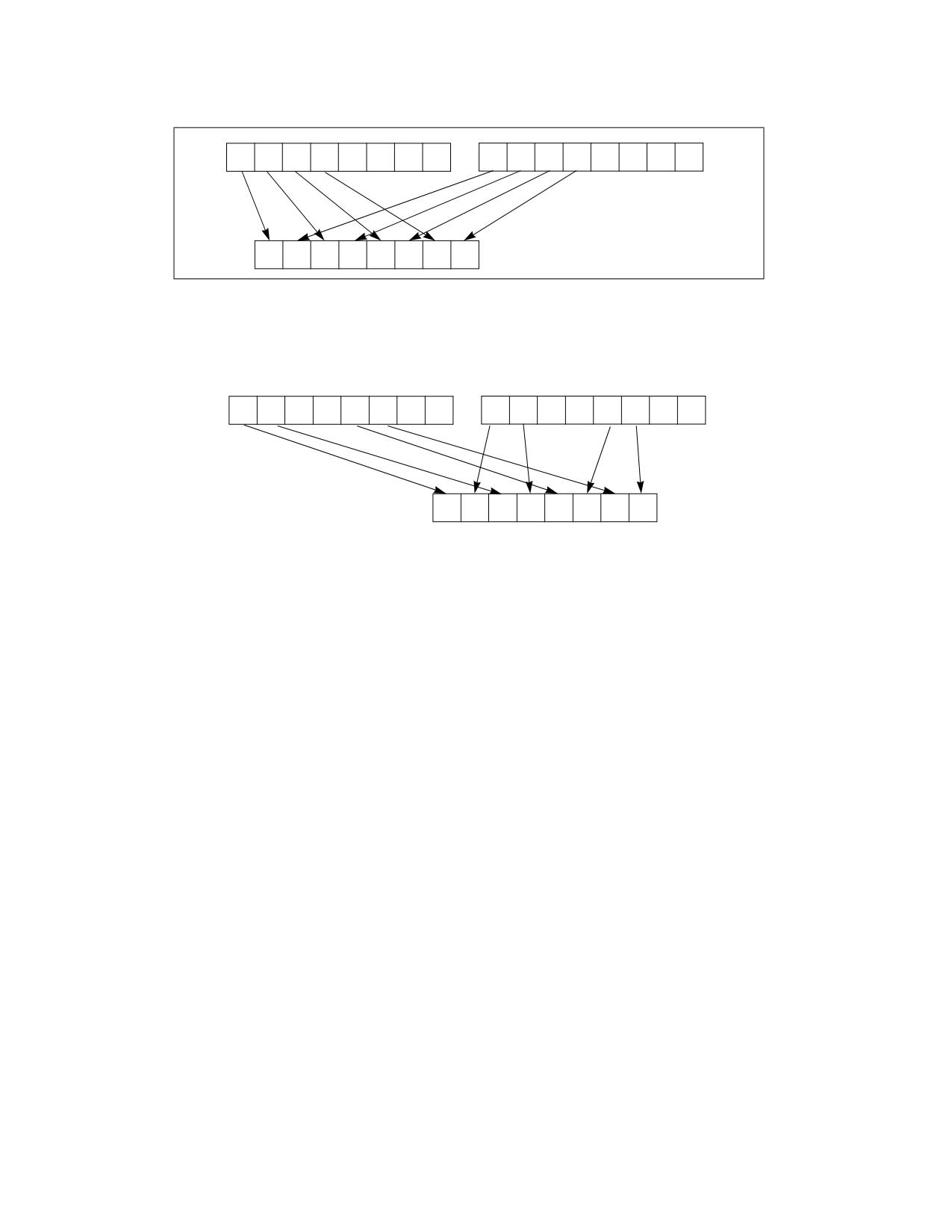
Unpacks and interleaves the high-order data elements (bytes, words, doublewords, or quadwords) of the destina-
tion operand (first operand) and source operand (second operand) into the destination operand. Figure 4-20 shows
the unpack operation for bytes in 64-bit operands. The low-order data elements are ignored.
PUNPCKHBW/PUNPCKHWD/PUNPCKHDQ/PUNPCKHQDQ- Unpack High Data
Vol. 2B
4-497
INSTRUCTION SET REFERENCE, M-U
SRC
Y7
Y6
Y5
Y4
Y3
Y2
Y1
Y0
X7
X6
X5
X4
X3
X2
X1
X0
DEST
DEST
Y7
X7
Y6
X6
Y5
X5
Y4
X4
Figure 4-20. PUNPCKHBW Instruction Operation Using 64-bit Operands
255
31
0
255
31
0
SRC
Y7
Y6
Y5
Y4
Y3
Y2
Y1
Y0
X7
X6
X5
X4
X3
X2
X1
X0
255
0
DEST
Y7
X7
Y6
X6
Y3
X3
Y2
X2
Figure 4-21. 256-bit VPUNPCKHDQ Instruction Operation
When the source data comes from a 64-bit memory operand, the full 64-bit operand is accessed from memory, but
the instruction uses only the high-order 32 bits. When the source data comes from a 128-bit memory operand, an
implementation may fetch only the appropriate 64 bits; however, alignment to a 16-byte boundary and normal
segment checking will still be enforced.
The (V)PUNPCKHBW instruction interleaves the high-order bytes of the source and destination operands, the
(V)PUNPCKHWD instruction interleaves the high-order words of the source and destination operands, the (V)PUNP-
CKHDQ instruction interleaves the high-order doubleword (or doublewords) of the source and destination oper-
ands, and the (V)PUNPCKHQDQ instruction interleaves the high-order quadwords of the source and destination
operands.
These instructions can be used to convert bytes to words, words to doublewords, doublewords to quadwords, and
quadwords to double quadwords, respectively, by placing all 0s in the source operand. Here, if the source operand
contains all 0s, the result (stored in the destination operand) contains zero extensions of the high-order data
elements from the original value in the destination operand. For example, with the (V)PUNPCKHBW instruction the
high-order bytes are zero extended (that is, unpacked into unsigned word integers), and with the (V)PUNPCKHWD
instruction, the high-order words are zero extended (unpacked into unsigned doubleword integers).
In 64-bit mode and not encoded with VEX/EVEX, using a REX prefix in the form of REX.R permits this instruction to
access additional registers (XMM8-XMM15).
Legacy SSE versions 64-bit operand: The source operand can be an MMX technology register or a 64-bit memory
location. The destination operand is an MMX technology register.
128-bit Legacy SSE versions: The second source operand is an XMM register or a 128-bit memory location. The first
source operand and destination operands are XMM registers. Bits (MAXVL-1:128) of the corresponding YMM desti-
nation register remain unchanged.
VEX.128 encoded versions: The second source operand is an XMM register or a 128-bit memory location. The first
source operand and destination operands are XMM registers. Bits (MAXVL-1:128) of the destination YMM register
are zeroed.
VEX.256 encoded version: The second source operand is an YMM register or an 256-bit memory location. The first
source operand and destination operands are YMM registers.
4-498
Vol. 2B
PUNPCKHBW/PUNPCKHWD/PUNPCKHDQ/PUNPCKHQDQ- Unpack High Data
INSTRUCTION SET REFERENCE, M-U
EVEX encoded VPUNPCKHDQ/QDQ: The second source operand is a ZMM/YMM/XMM register, a 512/256/128-bit
memory location or a 512/256/128-bit vector broadcasted from a 32/64-bit memory location. The first source
operand and destination operands are ZMM/YMM/XMM registers. The destination is conditionally updated with
writemask k1.
EVEX encoded VPUNPCKHWD/BW: The second source operand is a ZMM/YMM/XMM register, a 512/256/128-bit
memory location. The first source operand and destination operands are ZMM/YMM/XMM registers. The destination
is conditionally updated with writemask k1.
Operation
PUNPCKHBW Instruction With 64-bit Operands:
DEST[7:0] := DEST[39:32];
DEST[15:8] := SRC[39:32];
DEST[23:16] := DEST[47:40];
DEST[31:24] := SRC[47:40];
DEST[39:32] := DEST[55:48];
DEST[47:40] := SRC[55:48];
DEST[55:48] := DEST[63:56];
DEST[63:56] := SRC[63:56];
PUNPCKHW Instruction With 64-bit Operands:
DEST[15:0] := DEST[47:32];
DEST[31:16] := SRC[47:32];
DEST[47:32] := DEST[63:48];
DEST[63:48] := SRC[63:48];
PUNPCKHDQ Instruction With 64-bit Operands:
DEST[31:0] := DEST[63:32];
DEST[63:32] := SRC[63:32];
INTERLEAVE_HIGH_BYTES_512b (SRC1, SRC2)
TMP_DEST[255:0] := INTERLEAVE_HIGH_BYTES_256b(SRC1[255:0], SRC[255:0])
TMP_DEST[511:256] := INTERLEAVE_HIGH_BYTES_256b(SRC1[511:256], SRC[511:256])
INTERLEAVE_HIGH_BYTES_256b (SRC1, SRC2)
DEST[7:0] := SRC1[71:64]
DEST[15:8] := SRC2[71:64]
DEST[23:16] := SRC1[79:72]
DEST[31:24] := SRC2[79:72]
DEST[39:32] := SRC1[87:80]
DEST[47:40] := SRC2[87:80]
DEST[55:48] := SRC1[95:88]
DEST[63:56] := SRC2[95:88]
DEST[71:64] := SRC1[103:96]
DEST[79:72] := SRC2[103:96]
DEST[87:80] := SRC1[111:104]
DEST[95:88] := SRC2[111:104]
DEST[103:96] := SRC1[119:112]
DEST[111:104] := SRC2[119:112]
DEST[119:112] := SRC1[127:120]
DEST[127:120] := SRC2[127:120]
DEST[135:128] := SRC1[199:192]
DEST[143:136] := SRC2[199:192]
DEST[151:144] := SRC1[207:200]
DEST[159:152] := SRC2[207:200]
PUNPCKHBW/PUNPCKHWD/PUNPCKHDQ/PUNPCKHQDQ- Unpack High Data
Vol. 2B
4-499
INSTRUCTION SET REFERENCE, M-U
DEST[167:160] := SRC1[215:208]
DEST[175:168] := SRC2[215:208]
DEST[183:176] := SRC1[223:216]
DEST[191:184] := SRC2[223:216]
DEST[199:192] := SRC1[231:224]
DEST[207:200] := SRC2[231:224]
DEST[215:208] := SRC1[239:232]
DEST[223:216] := SRC2[239:232]
DEST[231:224] := SRC1[247:240]
DEST[239:232] := SRC2[247:240]
DEST[247:240] := SRC1[255:248]
DEST[255:248] := SRC2[255:248]
INTERLEAVE_HIGH_BYTES (SRC1, SRC2)
DEST[7:0] := SRC1[71:64]
DEST[15:8] := SRC2[71:64]
DEST[23:16] := SRC1[79:72]
DEST[31:24] := SRC2[79:72]
DEST[39:32] := SRC1[87:80]
DEST[47:40] := SRC2[87:80]
DEST[55:48] := SRC1[95:88]
DEST[63:56] := SRC2[95:88]
DEST[71:64] := SRC1[103:96]
DEST[79:72] := SRC2[103:96]
DEST[87:80] := SRC1[111:104]
DEST[95:88] := SRC2[111:104]
DEST[103:96] := SRC1[119:112]
DEST[111:104] := SRC2[119:112]
DEST[119:112] := SRC1[127:120]
DEST[127:120] := SRC2[127:120]
INTERLEAVE_HIGH_WORDS_512b (SRC1, SRC2)
TMP_DEST[255:0] := INTERLEAVE_HIGH_WORDS_256b(SRC1[255:0], SRC[255:0])
TMP_DEST[511:256] := INTERLEAVE_HIGH_WORDS_256b(SRC1[511:256], SRC[511:256])
INTERLEAVE_HIGH_WORDS_256b(SRC1, SRC2)
DEST[15:0] := SRC1[79:64]
DEST[31:16] := SRC2[79:64]
DEST[47:32] := SRC1[95:80]
DEST[63:48] := SRC2[95:80]
DEST[79:64] := SRC1[111:96]
DEST[95:80] := SRC2[111:96]
DEST[111:96] := SRC1[127:112]
DEST[127:112] := SRC2[127:112]
DEST[143:128] := SRC1[207:192]
DEST[159:144] := SRC2[207:192]
DEST[175:160] := SRC1[223:208]
DEST[191:176] := SRC2[223:208]
DEST[207:192] := SRC1[239:224]
DEST[223:208] := SRC2[239:224]
DEST[239:224] := SRC1[255:240]
DEST[255:240] := SRC2[255:240]
INTERLEAVE_HIGH_WORDS (SRC1, SRC2)
4-500
Vol. 2B
PUNPCKHBW/PUNPCKHWD/PUNPCKHDQ/PUNPCKHQDQ- Unpack High Data
INSTRUCTION SET REFERENCE, M-U
DEST[15:0] := SRC1[79:64]
DEST[31:16] := SRC2[79:64]
DEST[47:32] := SRC1[95:80]
DEST[63:48] := SRC2[95:80]
DEST[79:64] := SRC1[111:96]
DEST[95:80] := SRC2[111:96]
DEST[111:96] := SRC1[127:112]
DEST[127:112] := SRC2[127:112]
INTERLEAVE_HIGH_DWORDS_512b (SRC1, SRC2)
TMP_DEST[255:0] := INTERLEAVE_HIGH_DWORDS_256b(SRC1[255:0], SRC2[255:0])
TMP_DEST[511:256] := INTERLEAVE_HIGH_DWORDS_256b(SRC1[511:256], SRC2[511:256])
INTERLEAVE_HIGH_DWORDS_256b(SRC1, SRC2)
DEST[31:0] := SRC1[95:64]
DEST[63:32] := SRC2[95:64]
DEST[95:64] := SRC1[127:96]
DEST[127:96] := SRC2[127:96]
DEST[159:128] := SRC1[223:192]
DEST[191:160] := SRC2[223:192]
DEST[223:192] := SRC1[255:224]
DEST[255:224] := SRC2[255:224]
INTERLEAVE_HIGH_DWORDS(SRC1, SRC2)
DEST[31:0] := SRC1[95:64]
DEST[63:32] := SRC2[95:64]
DEST[95:64] := SRC1[127:96]
DEST[127:96] := SRC2[127:96]
INTERLEAVE_HIGH_QWORDS_512b (SRC1, SRC2)
TMP_DEST[255:0] := INTERLEAVE_HIGH_QWORDS_256b(SRC1[255:0], SRC2[255:0])
TMP_DEST[511:256] := INTERLEAVE_HIGH_QWORDS_256b(SRC1[511:256], SRC2[511:256])
INTERLEAVE_HIGH_QWORDS_256b(SRC1, SRC2)
DEST[63:0] := SRC1[127:64]
DEST[127:64] := SRC2[127:64]
DEST[191:128] := SRC1[255:192]
DEST[255:192] := SRC2[255:192]
INTERLEAVE_HIGH_QWORDS(SRC1, SRC2)
DEST[63:0] := SRC1[127:64]
DEST[127:64] := SRC2[127:64]
PUNPCKHBW (128-bit Legacy SSE Version)
DEST[127:0] := INTERLEAVE_HIGH_BYTES(DEST, SRC)
DEST[255:127] (Unmodified)
VPUNPCKHBW (VEX.128 Encoded Version)
DEST[127:0] := INTERLEAVE_HIGH_BYTES(SRC1, SRC2)
DEST[MAXVL-1:127] := 0
VPUNPCKHBW (VEX.256 Encoded Version)
DEST[255:0] := INTERLEAVE_HIGH_BYTES_256b(SRC1, SRC2)
DEST[MAXVL-1:256] := 0
PUNPCKHBW/PUNPCKHWD/PUNPCKHDQ/PUNPCKHQDQ- Unpack High Data
Vol. 2B
4-501
INSTRUCTION SET REFERENCE, M-U
VPUNPCKHBW (EVEX Encoded Versions)
(KL, VL) = (16, 128), (32, 256), (64, 512)
IF VL = 128
TMP_DEST[VL-1:0] := INTERLEAVE_HIGH_BYTES(SRC1[VL-1:0], SRC2[VL-1:0])
FI;
IF VL = 256
TMP_DEST[VL-1:0] := INTERLEAVE_HIGH_BYTES_256b(SRC1[VL-1:0], SRC2[VL-1:0])
FI;
IF VL = 512
TMP_DEST[VL-1:0] := INTERLEAVE_HIGH_BYTES_512b(SRC1[VL-1:0], SRC2[VL-1:0])
FI;
FOR j := 0 TO KL-1
i := j * 8
IF k1[j] OR *no writemask*
THEN DEST[i+7:i] := TMP_DEST[i+7:i]
ELSE
IF *merging-masking*
; merging-masking
THEN *DEST[i+7:i] remains unchanged*
ELSE *zeroing-masking*
; zeroing-masking
DEST[i+7:i] := 0
FI
FI;
ENDFOR
DEST[MAXVL-1:VL] := 0
PUNPCKHWD (128-bit Legacy SSE Version)
DEST[127:0] := INTERLEAVE_HIGH_WORDS(DEST, SRC)
DEST[255:127] (Unmodified)
VPUNPCKHWD (VEX.128 Encoded Version)
DEST[127:0] := INTERLEAVE_HIGH_WORDS(SRC1, SRC2)
DEST[MAXVL-1:127] := 0
VPUNPCKHWD (VEX.256 Encoded Version)
DEST[255:0] := INTERLEAVE_HIGH_WORDS_256b(SRC1, SRC2)
DEST[MAXVL-1:256] := 0
VPUNPCKHWD (EVEX Encoded Versions)
(KL, VL) = (8, 128), (16, 256), (32, 512)
IF VL = 128
TMP_DEST[VL-1:0] := INTERLEAVE_HIGH_WORDS(SRC1[VL-1:0], SRC2[VL-1:0])
FI;
IF VL = 256
TMP_DEST[VL-1:0] := INTERLEAVE_HIGH_WORDS_256b(SRC1[VL-1:0], SRC2[VL-1:0])
FI;
IF VL = 512
TMP_DEST[VL-1:0] := INTERLEAVE_HIGH_WORDS_512b(SRC1[VL-1:0], SRC2[VL-1:0])
FI;
FOR j := 0 TO KL-1
i := j * 16
IF k1[j] OR *no writemask*
4-502
Vol. 2B
PUNPCKHBW/PUNPCKHWD/PUNPCKHDQ/PUNPCKHQDQ- Unpack High Data
INSTRUCTION SET REFERENCE, M-U
THEN DEST[i+15:i] := TMP_DEST[i+15:i]
ELSE
IF *merging-masking*
; merging-masking
THEN *DEST[i+15:i] remains unchanged*
ELSE *zeroing-masking*
; zeroing-masking
DEST[i+15:i] := 0
FI
FI;
ENDFOR
DEST[MAXVL-1:VL] := 0
PUNPCKHDQ (128-bit Legacy SSE Version)
DEST[127:0] := INTERLEAVE_HIGH_DWORDS(DEST, SRC)
DEST[255:127] (Unmodified)
VPUNPCKHDQ (VEX.128 Encoded Version)
DEST[127:0] := INTERLEAVE_HIGH_DWORDS(SRC1, SRC2)
DEST[MAXVL-1:127] := 0
VPUNPCKHDQ (VEX.256 Encoded Version)
DEST[255:0] := INTERLEAVE_HIGH_DWORDS_256b(SRC1, SRC2)
DEST[MAXVL-1:256] := 0
VPUNPCKHDQ (EVEX.512 Encoded Version)
(KL, VL) = (4, 128), (8, 256), (16, 512)
FOR j := 0 TO KL-1
i := j * 32
IF (EVEX.b = 1) AND (SRC2 *is memory*)
THEN TMP_SRC2[i+31:i] := SRC2[31:0]
ELSE TMP_SRC2[i+31:i] := SRC2[i+31:i]
FI;
ENDFOR;
IF VL = 128
TMP_DEST[VL-1:0] := INTERLEAVE_HIGH_DWORDS(SRC1[VL-1:0], TMP_SRC2[VL-1:0])
FI;
IF VL = 256
TMP_DEST[VL-1:0] := INTERLEAVE_HIGH_DWORDS_256b(SRC1[VL-1:0], TMP_SRC2[VL-1:0])
FI;
IF VL = 512
TMP_DEST[VL-1:0] := INTERLEAVE_HIGH_DWORDS_512b(SRC1[VL-1:0], TMP_SRC2[VL-1:0])
FI;
FOR j := 0 TO KL-1
i := j * 32
IF k1[j] OR *no writemask*
THEN DEST[i+31:i] := TMP_DEST[i+31:i]
ELSE
IF *merging-masking*
; merging-masking
THEN *DEST[i+31:i] remains unchanged*
ELSE *zeroing-masking*
; zeroing-masking
DEST[i+31:i] := 0
FI
FI;
ENDFOR
PUNPCKHBW/PUNPCKHWD/PUNPCKHDQ/PUNPCKHQDQ- Unpack High Data
Vol. 2B
4-503
INSTRUCTION SET REFERENCE, M-U
DEST[MAXVL-1:VL] := 0
PUNPCKHQDQ (128-bit Legacy SSE Version)
DEST[127:0] := INTERLEAVE_HIGH_QWORDS(DEST, SRC)
DEST[MAXVL-1:128] (Unmodified)
VPUNPCKHQDQ (VEX.128 Encoded Version)
DEST[127:0] := INTERLEAVE_HIGH_QWORDS(SRC1, SRC2)
DEST[MAXVL-1:128] := 0
VPUNPCKHQDQ (VEX.256 Encoded Version)
DEST[255:0] := INTERLEAVE_HIGH_QWORDS_256b(SRC1, SRC2)
DEST[MAXVL-1:256] := 0
VPUNPCKHQDQ (EVEX Encoded Versions)
(KL, VL) = (2, 128), (4, 256), (8, 512)
FOR j := 0 TO KL-1
i := j * 64
IF (EVEX.b = 1) AND (SRC2 *is memory*)
THEN TMP_SRC2[i+63:i] := SRC2[63:0]
ELSE TMP_SRC2[i+63:i] := SRC2[i+63:i]
FI;
ENDFOR;
IF VL = 128
TMP_DEST[VL-1:0] := INTERLEAVE_HIGH_QWORDS(SRC1[VL-1:0], TMP_SRC2[VL-1:0])
FI;
IF VL = 256
TMP_DEST[VL-1:0] := INTERLEAVE_HIGH_QWORDS_256b(SRC1[VL-1:0], TMP_SRC2[VL-1:0])
FI;
IF VL = 512
TMP_DEST[VL-1:0] := INTERLEAVE_HIGH_QWORDS_512b(SRC1[VL-1:0], TMP_SRC2[VL-1:0])
FI;
FOR j := 0 TO KL-1
i := j * 64
IF k1[j] OR *no writemask*
THEN DEST[i+63:i] := TMP_DEST[i+63:i]
ELSE
IF *merging-masking*
; merging-masking
THEN *DEST[i+63:i] remains unchanged*
ELSE *zeroing-masking*
; zeroing-masking
DEST[i+63:i] := 0
FI
FI;
ENDFOR
DEST[MAXVL-1:VL] := 0
Intel C/C++ Compiler Intrinsic Equivalents
VPUNPCKHBW __m512i _mm512_unpackhi_epi8(__m512i a, __m512i b);
VPUNPCKHBW __m512i _mm512_mask_unpackhi_epi8(__m512i s, __mmask64 k, __m512i a, __m512i b);
VPUNPCKHBW __m512i _mm512_maskz_unpackhi_epi8( __mmask64 k, __m512i a, __m512i b);
VPUNPCKHBW __m256i _mm256_mask_unpackhi_epi8(__m256i s, __mmask32 k, __m256i a, __m256i b);
VPUNPCKHBW __m256i _mm256_maskz_unpackhi_epi8( __mmask32 k, __m256i a, __m256i b);
4-504
Vol. 2B
PUNPCKHBW/PUNPCKHWD/PUNPCKHDQ/PUNPCKHQDQ- Unpack High Data
INSTRUCTION SET REFERENCE, M-U
VPUNPCKHBW __m128i _mm_mask_unpackhi_epi8(v s, __mmask16 k, __m128i a, __m128i b);
VPUNPCKHBW __m128i _mm_maskz_unpackhi_epi8( __mmask16 k, __m128i a, __m128i b);
VPUNPCKHWD __m512i _mm512_unpackhi_epi16(__m512i a, __m512i b);
VPUNPCKHWD __m512i _mm512_mask_unpackhi_epi16(__m512i s, __mmask32 k, __m512i a, __m512i b);
VPUNPCKHWD __m512i _mm512_maskz_unpackhi_epi16( __mmask32 k, __m512i a, __m512i b);
VPUNPCKHWD __m256i _mm256_mask_unpackhi_epi16(__m256i s, __mmask16 k, __m256i a, __m256i b);
VPUNPCKHWD __m256i _mm256_maskz_unpackhi_epi16( __mmask16 k, __m256i a, __m256i b);
VPUNPCKHWD __m128i _mm_mask_unpackhi_epi16(v s, __mmask8 k, __m128i a, __m128i b);
VPUNPCKHWD __m128i _mm_maskz_unpackhi_epi16( __mmask8 k, __m128i a, __m128i b);
VPUNPCKHDQ __m512i _mm512_unpackhi_epi32(__m512i a, __m512i b);
VPUNPCKHDQ __m512i _mm512_mask_unpackhi_epi32(__m512i s, __mmask16 k, __m512i a, __m512i b);
VPUNPCKHDQ __m512i _mm512_maskz_unpackhi_epi32( __mmask16 k, __m512i a, __m512i b);
VPUNPCKHDQ __m256i _mm256_mask_unpackhi_epi32(__m512i s, __mmask8 k, __m512i a, __m512i b);
VPUNPCKHDQ __m256i _mm256_maskz_unpackhi_epi32( __mmask8 k, __m512i a, __m512i b);
VPUNPCKHDQ __m128i _mm_mask_unpackhi_epi32(__m512i s, __mmask8 k, __m512i a, __m512i b);
VPUNPCKHDQ __m128i _mm_maskz_unpackhi_epi32( __mmask8 k, __m512i a, __m512i b);
VPUNPCKHQDQ __m512i _mm512_unpackhi_epi64(__m512i a, __m512i b);
VPUNPCKHQDQ __m512i _mm512_mask_unpackhi_epi64(__m512i s, __mmask8 k, __m512i a, __m512i b);
VPUNPCKHQDQ __m512i _mm512_maskz_unpackhi_epi64( __mmask8 k, __m512i a, __m512i b);
VPUNPCKHQDQ __m256i _mm256_mask_unpackhi_epi64(__m512i s, __mmask8 k, __m512i a, __m512i b);
VPUNPCKHQDQ __m256i _mm256_maskz_unpackhi_epi64( __mmask8 k, __m512i a, __m512i b);
VPUNPCKHQDQ __m128i _mm_mask_unpackhi_epi64(__m512i s, __mmask8 k, __m512i a, __m512i b);
VPUNPCKHQDQ __m128i _mm_maskz_unpackhi_epi64( __mmask8 k, __m512i a, __m512i b);
PUNPCKHBW __m64 _mm_unpackhi_pi8(__m64 m1, __m64 m2)
(V)PUNPCKHBW __m128i _mm_unpackhi_epi8(__m128i m1, __m128i m2)
VPUNPCKHBW __m256i _mm256_unpackhi_epi8(__m256i m1, __m256i m2)
PUNPCKHWD __m64 _mm_unpackhi_pi16(__m64 m1,__m64 m2)
(V)PUNPCKHWD __m128i _mm_unpackhi_epi16(__m128i m1,__m128i m2)
VPUNPCKHWD __m256i _mm256_unpackhi_epi16(__m256i m1,__m256i m2)
PUNPCKHDQ __m64 _mm_unpackhi_pi32(__m64 m1, __m64 m2)
(V)PUNPCKHDQ __m128i _mm_unpackhi_epi32(__m128i m1, __m128i m2)
VPUNPCKHDQ __m256i _mm256_unpackhi_epi32(__m256i m1, __m256i m2)
(V)PUNPCKHQDQ __m128i _mm_unpackhi_epi64 ( __m128i a, __m128i b)
VPUNPCKHQDQ __m256i _mm256_unpackhi_epi64 ( __m256i a, __m256i b)
Flags Affected
None.
Numeric Exceptions
None.
Other Exceptions
Non-EVEX-encoded instruction, see Table 2-21, “Type 4 Class Exception Conditions.”
EVEX-encoded VPUNPCKHQDQ/QDQ, see Table 2-50, “Type E4NF Class Exception Conditions.”
EVEX-encoded VPUNPCKHBW/WD, see Exceptions Type E4NF.nb in Table 2-50, “Type E4NF Class Exception Condi-
tions.”
PUNPCKHBW/PUNPCKHWD/PUNPCKHDQ/PUNPCKHQDQ- Unpack High Data
Vol. 2B
4-505

INSTRUCTION SET REFERENCE, M-U
PUNPCKLBW/PUNPCKLWD/PUNPCKLDQ/PUNPCKLQDQ-Unpack Low Data
Opcode/
Op/
64/32 bit
CPUID
Description
Instruction
En
Mode
Feature
Support
Flag
NP 0F 60 /r1
A
V/V
MMX
Interleave low-order bytes from mm and
mm/m32 into mm.
PUNPCKLBW mm, mm/m32
66 0F 60 /r
A
V/V
SSE2
Interleave low-order bytes from xmm1 and
xmm2/m128 into xmm1.
PUNPCKLBW xmm1, xmm2/m128
NP 0F 61 /r1
A
V/V
MMX
Interleave low-order words from mm and
mm/m32 into mm.
PUNPCKLWD mm, mm/m32
66 0F 61 /r
A
V/V
SSE2
Interleave low-order words from xmm1 and
xmm2/m128 into xmm1.
PUNPCKLWD xmm1, xmm2/m128
NP 0F 62 /r1
A
V/V
MMX
Interleave low-order doublewords from mm
and mm/m32 into mm.
PUNPCKLDQ mm, mm/m32
66 0F 62 /r
A
V/V
SSE2
Interleave low-order doublewords from xmm1
and xmm2/m128 into xmm1.
PUNPCKLDQ xmm1, xmm2/m128
66 0F 6C /r
A
V/V
SSE2
Interleave low-order quadword from xmm1
and xmm2/m128 into xmm1 register.
PUNPCKLQDQ xmm1, xmm2/m128
VEX.128.66.0F.WIG 60/r
B
V/V
AVX
Interleave low-order bytes from xmm2 and
xmm3/m128 into xmm1.
VPUNPCKLBW xmm1,xmm2, xmm3/m128
VEX.128.66.0F.WIG 61/r
B
V/V
AVX
Interleave low-order words from xmm2 and
xmm3/m128 into xmm1.
VPUNPCKLWD xmm1,xmm2, xmm3/m128
VEX.128.66.0F.WIG 62/r
B
V/V
AVX
Interleave low-order doublewords from xmm2
and xmm3/m128 into xmm1.
VPUNPCKLDQ xmm1, xmm2, xmm3/m128
VEX.128.66.0F.WIG 6C/r
B
V/V
AVX
Interleave low-order quadword from xmm2
and xmm3/m128 into xmm1 register.
VPUNPCKLQDQ xmm1, xmm2, xmm3/m128
VEX.256.66.0F.WIG 60 /r
B
V/V
AVX2
Interleave low-order bytes from ymm2 and
ymm3/m256 into ymm1 register.
VPUNPCKLBW ymm1, ymm2, ymm3/m256
VEX.256.66.0F.WIG 61 /r
B
V/V
AVX2
Interleave low-order words from ymm2 and
ymm3/m256 into ymm1 register.
VPUNPCKLWD ymm1, ymm2, ymm3/m256
VEX.256.66.0F.WIG 62 /r
B
V/V
AVX2
Interleave low-order doublewords from ymm2
and ymm3/m256 into ymm1 register.
VPUNPCKLDQ ymm1, ymm2, ymm3/m256
VEX.256.66.0F.WIG 6C /r
B
V/V
AVX2
Interleave low-order quadword from ymm2
and ymm3/m256 into ymm1 register.
VPUNPCKLQDQ ymm1, ymm2, ymm3/m256
EVEX.128.66.0F.WIG 60 /r
C
V/V
AVX512VL
Interleave low-order bytes from xmm2 and
VPUNPCKLBW xmm1 {k1}{z}, xmm2, xmm3/m128
AVX512BW
xmm3/m128 into xmm1 register subject to
write mask k1.
EVEX.128.66.0F.WIG 61 /r
C
V/V
AVX512VL
Interleave low-order words from xmm2 and
VPUNPCKLWD xmm1 {k1}{z}, xmm2, xmm3/m128
AVX512BW
xmm3/m128 into xmm1 register subject to
write mask k1.
EVEX.128.66.0F.W0 62 /r
D
V/V
AVX512VL
Interleave low-order doublewords from xmm2
VPUNPCKLDQ xmm1 {k1}{z}, xmm2,
AVX512F
and xmm3/m128/m32bcst into xmm1
xmm3/m128/m32bcst
register subject to write mask k1.
EVEX.128.66.0F.W1 6C /r
D
V/V
AVX512VL
Interleave low-order quadword from zmm2
VPUNPCKLQDQ xmm1 {k1}{z}, xmm2,
AVX512F
and zmm3/m512/m64bcst into zmm1
xmm3/m128/m64bcst
register subject to write mask k1.
4-506
Vol. 2B
PUNPCKLBW/PUNPCKLWD/PUNPCKLDQ/PUNPCKLQDQ-Unpack Low Data

INSTRUCTION SET REFERENCE, M-U
Opcode/
Op/
64/32 bit
CPUID
Description
Instruction
En
Mode
Feature
Support
Flag
EVEX.256.66.0F.WIG 60 /r
C
V/V
AVX512VL
Interleave low-order bytes from ymm2 and
VPUNPCKLBW ymm1 {k1}{z}, ymm2, ymm3/m256
AVX512BW
ymm3/m256 into ymm1 register subject to
write mask k1.
EVEX.256.66.0F.WIG 61 /r
C
V/V
AVX512VL
Interleave low-order words from ymm2 and
VPUNPCKLWD ymm1 {k1}{z}, ymm2, ymm3/m256
AVX512BW
ymm3/m256 into ymm1 register subject to
write mask k1.
EVEX.256.66.0F.W0 62 /r
D
V/V
AVX512VL
Interleave low-order doublewords from ymm2
VPUNPCKLDQ ymm1 {k1}{z}, ymm2,
AVX512F
and ymm3/m256/m32bcst into ymm1
ymm3/m256/m32bcst
register subject to write mask k1.
EVEX.256.66.0F.W1 6C /r
D
V/V
AVX512VL
Interleave low-order quadword from ymm2
VPUNPCKLQDQ ymm1 {k1}{z}, ymm2,
AVX512F
and ymm3/m256/m64bcst into ymm1
ymm3/m256/m64bcst
register subject to write mask k1.
EVEX.512.66.0F.WIG 60/r
C
V/V
AVX512BW
Interleave low-order bytes from zmm2 and
VPUNPCKLBW zmm1 {k1}{z}, zmm2, zmm3/m512
zmm3/m512 into zmm1 register subject to
write mask k1.
EVEX.512.66.0F.WIG 61/r
C
V/V
AVX512BW
Interleave low-order words from zmm2 and
VPUNPCKLWD zmm1 {k1}{z}, zmm2, zmm3/m512
zmm3/m512 into zmm1 register subject to
write mask k1.
EVEX.512.66.0F.W0 62 /r
D
V/V
AVX512F
Interleave low-order doublewords from zmm2
VPUNPCKLDQ zmm1 {k1}{z}, zmm2,
and zmm3/m512/m32bcst into zmm1
zmm3/m512/m32bcst
register subject to write mask k1.
EVEX.512.66.0F.W1 6C /r
D
V/V
AVX512F
Interleave low-order quadword from zmm2
VPUNPCKLQDQ zmm1 {k1}{z}, zmm2,
and zmm3/m512/m64bcst into zmm1
zmm3/m512/m64bcst
register subject to write mask k1.
NOTES:
1. See note in Section 2.5, “Intel® AVX and Intel® SSE Instruction Exception Classification,” in the Intel® 64 and IA-32 Architectures Soft-
ware Developer’s Manual, Volume 2A, and Section 23.25.3, “Exception Conditions of Legacy SIMD Instructions Operating on MMX Reg-
isters,” in the Intel® 64 and IA-32 Architectures Software Developer’s Manual, Volume 3B.
Instruction Operand Encoding
Op/En
Tuple Type
Operand 1
Operand 2
Operand 3
Operand 4
A
N/A
ModRM:reg (r, w)
ModRM:r/m (r)
N/A
N/A
B
N/A
ModRM:reg (w)
VEX.vvvv (r)
ModRM:r/m (r)
N/A
C
Full Mem
ModRM:reg (w)
EVEX.vvvv (r)
ModRM:r/m (r)
N/A
D
Full
ModRM:reg (w)
EVEX.vvvv (r)
ModRM:r/m (r)
N/A
Description
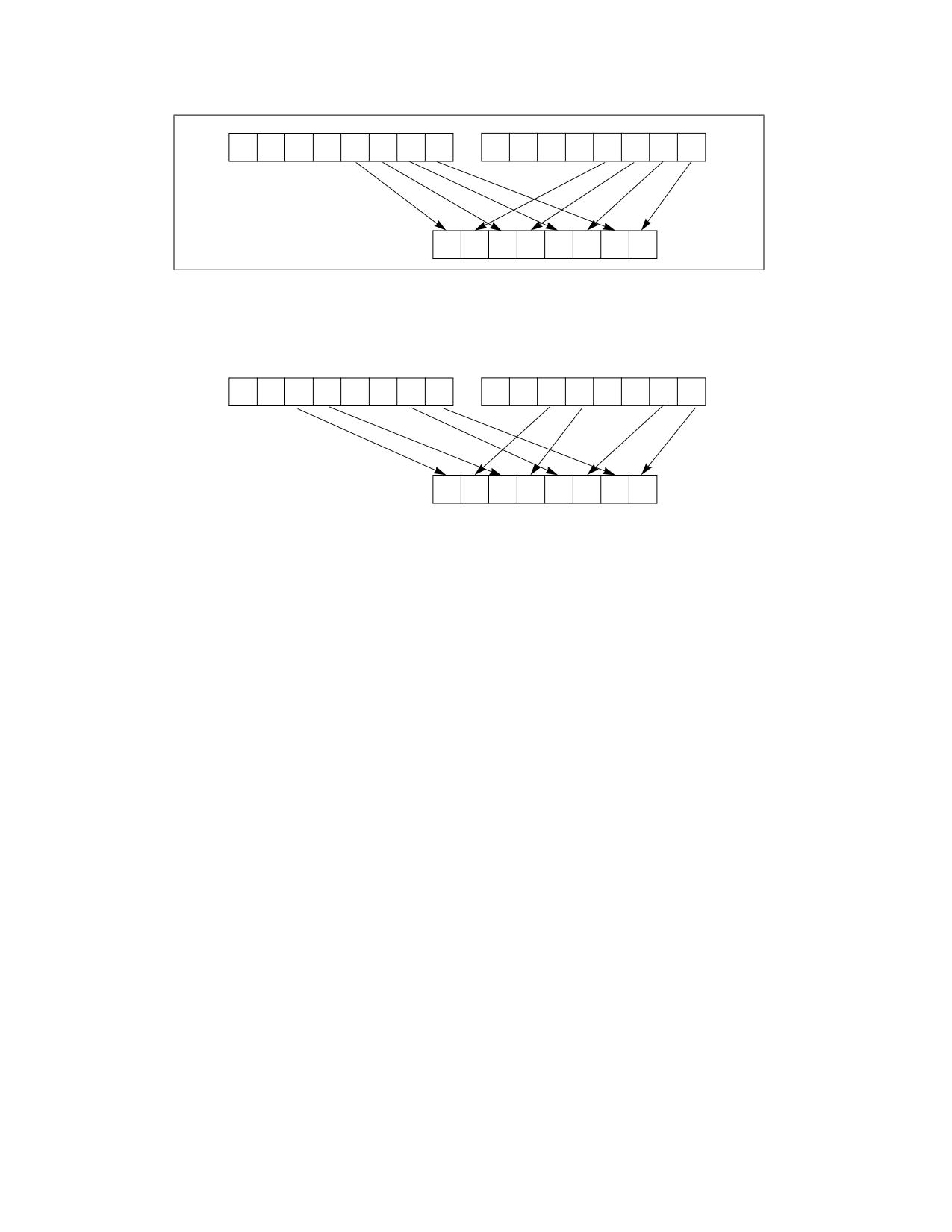
Unpacks and interleaves the low-order data elements (bytes, words, doublewords, and quadwords) of the destina-
tion operand (first operand) and source operand (second operand) into the destination operand. (Figure 4-22
shows the unpack operation for bytes in 64-bit operands.). The high-order data elements are ignored.
PUNPCKLBW/PUNPCKLWD/PUNPCKLDQ/PUNPCKLQDQ-Unpack Low Data
Vol. 2B
4-507
INSTRUCTION SET REFERENCE, M-U
SRC
Y7
Y6
Y5
Y4
Y3
Y2
Y1
Y0
X7
X6
X5
X4
X3
X2
X1
X0
DEST
DEST
Y3
X3
Y2
X2
Y1
X1
Y0
X0
Figure 4-22. PUNPCKLBW Instruction Operation Using 64-bit Operands
255
31
0
255
31
0
SRC
Y7
Y6
Y5
Y4
Y3
Y2
Y1
Y0
X7
X6
X5
X4
X3
X2
X1
X0
255
0
DEST
Y5
X5
Y4
X4
Y1
X1
Y0
X0
Figure 4-23. 256-bit VPUNPCKLDQ Instruction Operation
When the source data comes from a 128-bit memory operand, an implementation may fetch only the appropriate
64 bits; however, alignment to a 16-byte boundary and normal segment checking will still be enforced.
The (V)PUNPCKLBW instruction interleaves the low-order bytes of the source and destination operands, the
(V)PUNPCKLWD instruction interleaves the low-order words of the source and destination operands, the (V)PUNP-
CKLDQ instruction interleaves the low-order doubleword (or doublewords) of the source and destination operands,
and the (V)PUNPCKLQDQ instruction interleaves the low-order quadwords of the source and destination operands.
These instructions can be used to convert bytes to words, words to doublewords, doublewords to quadwords, and
quadwords to double quadwords, respectively, by placing all 0s in the source operand. Here, if the source operand
contains all 0s, the result (stored in the destination operand) contains zero extensions of the high-order data
elements from the original value in the destination operand. For example, with the (V)PUNPCKLBW instruction the
high-order bytes are zero extended (that is, unpacked into unsigned word integers), and with the (V)PUNPCKLWD
instruction, the high-order words are zero extended (unpacked into unsigned doubleword integers).
In 64-bit mode and not encoded with VEX/EVEX, using a REX prefix in the form of REX.R permits this instruction to
access additional registers (XMM8-XMM15).
Legacy SSE versions 64-bit operand: The source operand can be an MMX technology register or a 32-bit memory
location. The destination operand is an MMX technology register.
128-bit Legacy SSE versions: The second source operand is an XMM register or a 128-bit memory location. The first
source operand and destination operands are XMM registers. Bits (MAXVL-1:128) of the corresponding YMM desti-
nation register remain unchanged.
VEX.128 encoded versions: The second source operand is an XMM register or a 128-bit memory location. The first
source operand and destination operands are XMM registers. Bits (MAXVL-1:128) of the destination YMM register
are zeroed.
VEX.256 encoded version: The second source operand is an YMM register or an 256-bit memory location. The first
source operand and destination operands are YMM registers. Bits (MAXVL-1:256) of the corresponding ZMM
register are zeroed.
EVEX encoded VPUNPCKLDQ/QDQ: The second source operand is a ZMM/YMM/XMM register, a 512/256/128-bit
memory location or a 512/256/128-bit vector broadcasted from a 32/64-bit memory location. The first source
4-508
Vol. 2B
PUNPCKLBW/PUNPCKLWD/PUNPCKLDQ/PUNPCKLQDQ-Unpack Low Data
INSTRUCTION SET REFERENCE, M-U
operand and destination operands are ZMM/YMM/XMM registers. The destination is conditionally updated with
writemask k1.
EVEX encoded VPUNPCKLWD/BW: The second source operand is a ZMM/YMM/XMM register, a 512/256/128-bit
memory location. The first source operand and destination operands are ZMM/YMM/XMM registers. The destination
is conditionally updated with writemask k1.
Operation
PUNPCKLBW Instruction With 64-bit Operands:
DEST[63:56] := SRC[31:24];
DEST[55:48] := DEST[31:24];
DEST[47:40] := SRC[23:16];
DEST[39:32] := DEST[23:16];
DEST[31:24] := SRC[15:8];
DEST[23:16] := DEST[15:8];
DEST[15:8] := SRC[7:0];
DEST[7:0] := DEST[7:0];
PUNPCKLWD Instruction With 64-bit Operands:
DEST[63:48] := SRC[31:16];
DEST[47:32] := DEST[31:16];
DEST[31:16] := SRC[15:0];
DEST[15:0] := DEST[15:0];
PUNPCKLDQ Instruction With 64-bit Operands:
DEST[63:32] := SRC[31:0];
DEST[31:0] := DEST[31:0];
INTERLEAVE_BYTES_512b (SRC1, SRC2)
TMP_DEST[255:0] := INTERLEAVE_BYTES_256b(SRC1[255:0], SRC[255:0])
TMP_DEST[511:256] := INTERLEAVE_BYTES_256b(SRC1[511:256], SRC[511:256])
INTERLEAVE_BYTES_256b (SRC1, SRC2)
DEST[7:0] := SRC1[7:0]
DEST[15:8] := SRC2[7:0]
DEST[23:16] := SRC1[15:8]
DEST[31:24] := SRC2[15:8]
DEST[39:32] := SRC1[23:16]
DEST[47:40] := SRC2[23:16]
DEST[55:48] := SRC1[31:24]
DEST[63:56] := SRC2[31:24]
DEST[71:64] := SRC1[39:32]
DEST[79:72] := SRC2[39:32]
DEST[87:80] := SRC1[47:40]
DEST[95:88] := SRC2[47:40]
DEST[103:96] := SRC1[55:48]
DEST[111:104] := SRC2[55:48]
DEST[119:112] := SRC1[63:56]
DEST[127:120] := SRC2[63:56]
DEST[135:128] := SRC1[135:128]
DEST[143:136] := SRC2[135:128]
DEST[151:144] := SRC1[143:136]
DEST[159:152] := SRC2[143:136]
DEST[167:160] := SRC1[151:144]
DEST[175:168] := SRC2[151:144]
PUNPCKLBW/PUNPCKLWD/PUNPCKLDQ/PUNPCKLQDQ-Unpack Low Data
Vol. 2B
4-509
INSTRUCTION SET REFERENCE, M-U
DEST[183:176] := SRC1[159:152]
DEST[191:184] := SRC2[159:152]
DEST[199:192] := SRC1[167:160]
DEST[207:200] := SRC2[167:160]
DEST[215:208] := SRC1[175:168]
DEST[223:216] := SRC2[175:168]
DEST[231:224] := SRC1[183:176]
DEST[239:232] := SRC2[183:176]
DEST[247:240] := SRC1[191:184]
DEST[255:248] := SRC2[191:184]
INTERLEAVE_BYTES (SRC1, SRC2)
DEST[7:0] := SRC1[7:0]
DEST[15:8] := SRC2[7:0]
DEST[23:16] := SRC1[15:8]
DEST[31:24] := SRC2[15:8]
DEST[39:32] := SRC1[23:16]
DEST[47:40] := SRC2[23:16]
DEST[55:48] := SRC1[31:24]
DEST[63:56] := SRC2[31:24]
DEST[71:64] := SRC1[39:32]
DEST[79:72] := SRC2[39:32]
DEST[87:80] := SRC1[47:40]
DEST[95:88] := SRC2[47:40]
DEST[103:96] := SRC1[55:48]
DEST[111:104] := SRC2[55:48]
DEST[119:112] := SRC1[63:56]
DEST[127:120] := SRC2[63:56]
INTERLEAVE_WORDS_512b (SRC1, SRC2)
TMP_DEST[255:0] := INTERLEAVE_WORDS_256b(SRC1[255:0], SRC[255:0])
TMP_DEST[511:256] := INTERLEAVE_WORDS_256b(SRC1[511:256], SRC[511:256])
INTERLEAVE_WORDS_256b(SRC1, SRC2)
DEST[15:0] := SRC1[15:0]
DEST[31:16] := SRC2[15:0]
DEST[47:32] := SRC1[31:16]
DEST[63:48] := SRC2[31:16]
DEST[79:64] := SRC1[47:32]
DEST[95:80] := SRC2[47:32]
DEST[111:96] := SRC1[63:48]
DEST[127:112] := SRC2[63:48]
DEST[143:128] := SRC1[143:128]
DEST[159:144] := SRC2[143:128]
DEST[175:160] := SRC1[159:144]
DEST[191:176] := SRC2[159:144]
DEST[207:192] := SRC1[175:160]
DEST[223:208] := SRC2[175:160]
DEST[239:224] := SRC1[191:176]
DEST[255:240] := SRC2[191:176]
INTERLEAVE_WORDS (SRC1, SRC2)
DEST[15:0] := SRC1[15:0]
DEST[31:16] := SRC2[15:0]
4-510
Vol. 2B
PUNPCKLBW/PUNPCKLWD/PUNPCKLDQ/PUNPCKLQDQ-Unpack Low Data
INSTRUCTION SET REFERENCE, M-U
DEST[47:32] := SRC1[31:16]
DEST[63:48] := SRC2[31:16]
DEST[79:64] := SRC1[47:32]
DEST[95:80] := SRC2[47:32]
DEST[111:96] := SRC1[63:48]
DEST[127:112] := SRC2[63:48]
INTERLEAVE_DWORDS_512b (SRC1, SRC2)
TMP_DEST[255:0] := INTERLEAVE_DWORDS_256b(SRC1[255:0], SRC2[255:0])
TMP_DEST[511:256] := INTERLEAVE_DWORDS_256b(SRC1[511:256], SRC2[511:256])
INTERLEAVE_DWORDS_256b(SRC1, SRC2)
DEST[31:0] := SRC1[31:0]
DEST[63:32] := SRC2[31:0]
DEST[95:64] := SRC1[63:32]
DEST[127:96] := SRC2[63:32]
DEST[159:128] := SRC1[159:128]
DEST[191:160] := SRC2[159:128]
DEST[223:192] := SRC1[191:160]
DEST[255:224] := SRC2[191:160]
INTERLEAVE_DWORDS(SRC1, SRC2)
DEST[31:0] := SRC1[31:0]
DEST[63:32] := SRC2[31:0]
DEST[95:64] := SRC1[63:32]
DEST[127:96] := SRC2[63:32]
INTERLEAVE_QWORDS_512b (SRC1, SRC2)
TMP_DEST[255:0] := INTERLEAVE_QWORDS_256b(SRC1[255:0], SRC2[255:0])
TMP_DEST[511:256] := INTERLEAVE_QWORDS_256b(SRC1[511:256], SRC2[511:256])
INTERLEAVE_QWORDS_256b(SRC1, SRC2)
DEST[63:0] := SRC1[63:0]
DEST[127:64] := SRC2[63:0]
DEST[191:128] := SRC1[191:128]
DEST[255:192] := SRC2[191:128]
INTERLEAVE_QWORDS(SRC1, SRC2)
DEST[63:0] := SRC1[63:0]
DEST[127:64] := SRC2[63:0]
PUNPCKLBW
DEST[127:0] := INTERLEAVE_BYTES(DEST, SRC)
DEST[255:127] (Unmodified)
VPUNPCKLBW (VEX.128 Encoded Instruction)
DEST[127:0] := INTERLEAVE_BYTES(SRC1, SRC2)
DEST[MAXVL-1:127] := 0
VPUNPCKLBW (VEX.256 Encoded Instruction)
DEST[255:0] := INTERLEAVE_BYTES_256b(SRC1, SRC2)
DEST[MAXVL-1:256] := 0
PUNPCKLBW/PUNPCKLWD/PUNPCKLDQ/PUNPCKLQDQ-Unpack Low Data
Vol. 2B
4-511
INSTRUCTION SET REFERENCE, M-U
VPUNPCKLBW (EVEX.512 Encoded Instruction)
(KL, VL) = (16, 128), (32, 256), (64, 512)
IF VL = 128
TMP_DEST[VL-1:0] := INTERLEAVE_BYTES(SRC1[VL-1:0], SRC2[VL-1:0])
FI;
IF VL = 256
TMP_DEST[VL-1:0] := INTERLEAVE_BYTES_256b(SRC1[VL-1:0], SRC2[VL-1:0])
FI;
IF VL = 512
TMP_DEST[VL-1:0] := INTERLEAVE_BYTES_512b(SRC1[VL-1:0], SRC2[VL-1:0])
FI;
FOR j := 0 TO KL-1
i := j * 8
IF k1[j] OR *no writemask*
THEN DEST[i+7:i] := TMP_DEST[i+7:i]
ELSE
IF *merging-masking*
; merging-masking
THEN *DEST[i+7:i] remains unchanged*
ELSE *zeroing-masking*
; zeroing-masking
DEST[i+7:i] := 0
FI
FI;
ENDFOR
DEST[MAXVL-1:VL] := 0
DEST[511:0] := INTERLEAVE_BYTES_512b(SRC1, SRC2)
PUNPCKLWD
DEST[127:0] := INTERLEAVE_WORDS(DEST, SRC)
DEST[255:127] (Unmodified)
VPUNPCKLWD (VEX.128 Encoded Instruction)
DEST[127:0] := INTERLEAVE_WORDS(SRC1, SRC2)
DEST[MAXVL-1:127] := 0
VPUNPCKLWD (VEX.256 Encoded Instruction)
DEST[255:0] := INTERLEAVE_WORDS_256b(SRC1, SRC2)
DEST[MAXVL-1:256] := 0
VPUNPCKLWD (EVEX.512 Encoded Instruction)
(KL, VL) = (8, 128), (16, 256), (32, 512)
IF VL = 128
TMP_DEST[VL-1:0] := INTERLEAVE_WORDS(SRC1[VL-1:0], SRC2[VL-1:0])
FI;
IF VL = 256
TMP_DEST[VL-1:0] := INTERLEAVE_WORDS_256b(SRC1[VL-1:0], SRC2[VL-1:0])
FI;
IF VL = 512
TMP_DEST[VL-1:0] := INTERLEAVE_WORDS_512b(SRC1[VL-1:0], SRC2[VL-1:0])
FI;
FOR j := 0 TO KL-1
i := j * 16
IF k1[j] OR *no writemask*
4-512
Vol. 2B
PUNPCKLBW/PUNPCKLWD/PUNPCKLDQ/PUNPCKLQDQ-Unpack Low Data
INSTRUCTION SET REFERENCE, M-U
THEN DEST[i+15:i] := TMP_DEST[i+15:i]
ELSE
IF *merging-masking*
; merging-masking
THEN *DEST[i+15:i] remains unchanged*
ELSE *zeroing-masking*
; zeroing-masking
DEST[i+15:i] := 0
FI
FI;
ENDFOR
DEST[MAXVL-1:VL] := 0
DEST[511:0] := INTERLEAVE_WORDS_512b(SRC1, SRC2)
PUNPCKLDQ
DEST[127:0] := INTERLEAVE_DWORDS(DEST, SRC)
DEST[MAXVL-1:128] (Unmodified)
VPUNPCKLDQ (VEX.128 Encoded Instruction)
DEST[127:0] := INTERLEAVE_DWORDS(SRC1, SRC2)
DEST[MAXVL-1:128] := 0
VPUNPCKLDQ (VEX.256 Encoded Instruction)
DEST[255:0] := INTERLEAVE_DWORDS_256b(SRC1, SRC2)
DEST[MAXVL-1:256] := 0
VPUNPCKLDQ (EVEX Encoded Instructions)
(KL, VL) = (4, 128), (8, 256), (16, 512)
FOR j := 0 TO KL-1
i := j * 32
IF (EVEX.b = 1) AND (SRC2 *is memory*)
THEN TMP_SRC2[i+31:i] := SRC2[31:0]
ELSE TMP_SRC2[i+31:i] := SRC2[i+31:i]
FI;
ENDFOR;
IF VL = 128
TMP_DEST[VL-1:0] := INTERLEAVE_DWORDS(SRC1[VL-1:0], TMP_SRC2[VL-1:0])
FI;
IF VL = 256
TMP_DEST[VL-1:0] := INTERLEAVE_DWORDS_256b(SRC1[VL-1:0], TMP_SRC2[VL-1:0])
FI;
IF VL = 512
TMP_DEST[VL-1:0] := INTERLEAVE_DWORDS_512b(SRC1[VL-1:0], TMP_SRC2[VL-1:0])
FI;
FOR j := 0 TO KL-1
i := j * 32
IF k1[j] OR *no writemask*
THEN DEST[i+31:i] := TMP_DEST[i+31:i]
ELSE
IF *merging-masking*
; merging-masking
THEN *DEST[i+31:i] remains unchanged*
ELSE *zeroing-masking*
; zeroing-masking
DEST[i+31:i] := 0
FI
FI;
PUNPCKLBW/PUNPCKLWD/PUNPCKLDQ/PUNPCKLQDQ-Unpack Low Data
Vol. 2B
4-513
INSTRUCTION SET REFERENCE, M-U
ENDFOR
DEST511:0] := INTERLEAVE_DWORDS_512b(SRC1, SRC2)
DEST[MAXVL-1:VL] := 0
PUNPCKLQDQ
DEST[127:0] := INTERLEAVE_QWORDS(DEST, SRC)
DEST[MAXVL-1:128] (Unmodified)
VPUNPCKLQDQ (VEX.128 Encoded Instruction)
DEST[127:0] := INTERLEAVE_QWORDS(SRC1, SRC2)
DEST[MAXVL-1:128] := 0
VPUNPCKLQDQ (VEX.256 Encoded Instruction)
DEST[255:0] := INTERLEAVE_QWORDS_256b(SRC1, SRC2)
DEST[MAXVL-1:256] := 0
VPUNPCKLQDQ (EVEX Encoded Instructions)
(KL, VL) = (2, 128), (4, 256), (8, 512)
FOR j := 0 TO KL-1
i := j * 64
IF (EVEX.b = 1) AND (SRC2 *is memory*)
THEN TMP_SRC2[i+63:i] := SRC2[63:0]
ELSE TMP_SRC2[i+63:i] := SRC2[i+63:i]
FI;
ENDFOR;
IF VL = 128
TMP_DEST[VL-1:0] := INTERLEAVE_QWORDS(SRC1[VL-1:0], TMP_SRC2[VL-1:0])
FI;
IF VL = 256
TMP_DEST[VL-1:0] := INTERLEAVE_QWORDS_256b(SRC1[VL-1:0], TMP_SRC2[VL-1:0])
FI;
IF VL = 512
TMP_DEST[VL-1:0] := INTERLEAVE_QWORDS_512b(SRC1[VL-1:0], TMP_SRC2[VL-1:0])
FI;
FOR j := 0 TO KL-1
i := j * 64
IF k1[j] OR *no writemask*
THEN DEST[i+63:i] := TMP_DEST[i+63:i]
ELSE
IF *merging-masking*
; merging-masking
THEN *DEST[i+63:i] remains unchanged*
ELSE *zeroing-masking*
; zeroing-masking
DEST[i+63:i] := 0
FI
FI;
ENDFOR
DEST[MAXVL-1:VL] := 0
Intel C/C++ Compiler Intrinsic Equivalents
VPUNPCKLBW __m512i _mm512_unpacklo_epi8(__m512i a, __m512i b);
VPUNPCKLBW __m512i _mm512_mask_unpacklo_epi8(__m512i s, __mmask64 k, __m512i a, __m512i b);
VPUNPCKLBW __m512i _mm512_maskz_unpacklo_epi8( __mmask64 k, __m512i a, __m512i b);
4-514
Vol. 2B
PUNPCKLBW/PUNPCKLWD/PUNPCKLDQ/PUNPCKLQDQ-Unpack Low Data
INSTRUCTION SET REFERENCE, M-U
VPUNPCKLBW __m256i _mm256_mask_unpacklo_epi8(__m256i s, __mmask32 k, __m256i a, __m256i b);
VPUNPCKLBW __m256i _mm256_maskz_unpacklo_epi8( __mmask32 k, __m256i a, __m256i b);
VPUNPCKLBW __m128i _mm_mask_unpacklo_epi8(v s, __mmask16 k, __m128i a, __m128i b);
VPUNPCKLBW __m128i _mm_maskz_unpacklo_epi8( __mmask16 k, __m128i a, __m128i b);
VPUNPCKLWD __m512i _mm512_unpacklo_epi16(__m512i a, __m512i b);
VPUNPCKLWD __m512i _mm512_mask_unpacklo_epi16(__m512i s, __mmask32 k, __m512i a, __m512i b);
VPUNPCKLWD __m512i _mm512_maskz_unpacklo_epi16( __mmask32 k, __m512i a, __m512i b);
VPUNPCKLWD __m256i _mm256_mask_unpacklo_epi16(__m256i s, __mmask16 k, __m256i a, __m256i b);
VPUNPCKLWD __m256i _mm256_maskz_unpacklo_epi16( __mmask16 k, __m256i a, __m256i b);
VPUNPCKLWD __m128i _mm_mask_unpacklo_epi16(v s, __mmask8 k, __m128i a, __m128i b);
VPUNPCKLWD __m128i _mm_maskz_unpacklo_epi16( __mmask8 k, __m128i a, __m128i b);
VPUNPCKLDQ __m512i _mm512_unpacklo_epi32(__m512i a, __m512i b);
VPUNPCKLDQ __m512i _mm512_mask_unpacklo_epi32(__m512i s, __mmask16 k, __m512i a, __m512i b);
VPUNPCKLDQ __m512i _mm512_maskz_unpacklo_epi32( __mmask16 k, __m512i a, __m512i b);
VPUNPCKLDQ __m256i _mm256_mask_unpacklo_epi32(__m256i s, __mmask8 k, __m256i a, __m256i b);
VPUNPCKLDQ __m256i _mm256_maskz_unpacklo_epi32( __mmask8 k, __m256i a, __m256i b);
VPUNPCKLDQ __m128i _mm_mask_unpacklo_epi32(v s, __mmask8 k, __m128i a, __m128i b);
VPUNPCKLDQ __m128i _mm_maskz_unpacklo_epi32( __mmask8 k, __m128i a, __m128i b);
VPUNPCKLQDQ __m512i _mm512_unpacklo_epi64(__m512i a, __m512i b);
VPUNPCKLQDQ __m512i _mm512_mask_unpacklo_epi64(__m512i s, __mmask8 k, __m512i a, __m512i b);
VPUNPCKLQDQ __m512i _mm512_maskz_unpacklo_epi64( __mmask8 k, __m512i a, __m512i b);
VPUNPCKLQDQ __m256i _mm256_mask_unpacklo_epi64(__m256i s, __mmask8 k, __m256i a, __m256i b);
VPUNPCKLQDQ __m256i _mm256_maskz_unpacklo_epi64( __mmask8 k, __m256i a, __m256i b);
VPUNPCKLQDQ __m128i _mm_mask_unpacklo_epi64(__m128i s, __mmask8 k, __m128i a, __m128i b);
VPUNPCKLQDQ __m128i _mm_maskz_unpacklo_epi64( __mmask8 k, __m128i a, __m128i b);
PUNPCKLBW __m64 _mm_unpacklo_pi8 (__m64 m1, __m64 m2)
(V)PUNPCKLBW __m128i _mm_unpacklo_epi8 (__m128i m1, __m128i m2)
VPUNPCKLBW __m256i _mm256_unpacklo_epi8 (__m256i m1, __m256i m2)
PUNPCKLWD __m64 _mm_unpacklo_pi16 (__m64 m1, __m64 m2)
(V)PUNPCKLWD __m128i _mm_unpacklo_epi16 (__m128i m1, __m128i m2)
VPUNPCKLWD __m256i _mm256_unpacklo_epi16 (__m256i m1, __m256i m2)
PUNPCKLDQ __m64 _mm_unpacklo_pi32 (__m64 m1, __m64 m2)
(V)PUNPCKLDQ __m128i _mm_unpacklo_epi32 (__m128i m1, __m128i m2)
VPUNPCKLDQ __m256i _mm256_unpacklo_epi32 (__m256i m1, __m256i m2)
(V)PUNPCKLQDQ __m128i _mm_unpacklo_epi64 (__m128i m1, __m128i m2)
VPUNPCKLQDQ __m256i _mm256_unpacklo_epi64 (__m256i m1, __m256i m2)
Flags Affected
None.
Numeric Exceptions
None.
Other Exceptions
Non-EVEX-encoded instruction, see Table 2-21, “Type 4 Class Exception Conditions.”
EVEX-encoded VPUNPCKLDQ/QDQ, see Table 2-50, “Type E4NF Class Exception Conditions.”
EVEX-encoded VPUNPCKLBW/WD, see Exceptions Type E4NF.nb in Table 2-50, “Type E4NF Class Exception Condi-
tions.”
PUNPCKLBW/PUNPCKLWD/PUNPCKLDQ/PUNPCKLQDQ-Unpack Low Data
Vol. 2B
4-515

INSTRUCTION SET REFERENCE, M-U
PUSH-Push Word, Doubleword, or Quadword Onto the Stack
Opcode1
Instruction
Op/
64-Bit
Compat/
Description
En
Mode
Leg Mode
FF /6
PUSH r/m16
M
Valid
Valid
Push r/m16.
FF /6
PUSH r/m32
M
N.E.
Valid
Push r/m32.
FF /6
PUSH r/m64
M
Valid
N.E.
Push r/m64.
50+rw
PUSH r16
O
Valid
Valid
Push r16.
50+rd
PUSH r32
O
N.E.
Valid
Push r32.
50+rd
PUSH r64
O
Valid
N.E.
Push r64.
6A ib
PUSH imm8
I
Valid
Valid
Push imm8.
68 iw
PUSH imm16
I
Valid
Valid
Push imm16.
68 id
PUSH imm32
I
Valid
Valid
Push imm32.
0E
PUSH CS
ZO
Invalid
Valid
Push CS.
16
PUSH SS
ZO
Invalid
Valid
Push SS.
1E
PUSH DS
ZO
Invalid
Valid
Push DS.
06
PUSH ES
ZO
Invalid
Valid
Push ES.
0F A0
PUSH FS
ZO
Valid
Valid
Push FS.
0F A8
PUSH GS
ZO
Valid
Valid
Push GS.
NOTES:
1. See the IA-32 Architecture Compatibility section below.
Instruction Operand Encoding
Op/En
Operand 1
Operand 2
Operand 3
Operand 4
M
ModRM:r/m (r)
N/A
N/A
N/A
O
opcode + rd (r)
N/A
N/A
N/A
I
imm8/16/32
N/A
N/A
N/A
ZO
N/A
N/A
N/A
N/A
Description
Decrements the stack pointer and then stores the source operand on the top of the stack. Address and operand
sizes are determined and used as follows:
• Address size. The D flag in the current code-segment descriptor determines the default address size; it may be
overridden by an instruction prefix (67H).
The address size is used only when referencing a source operand in memory.
• Operand size. The D flag in the current code-segment descriptor determines the default operand size; it may
be overridden by instruction prefixes (66H or REX.W).
The operand size (16, 32, or 64 bits) determines the amount by which the stack pointer is decremented (2, 4
or 8).
If the source operand is an immediate of size less than the operand size, a sign-extended value is pushed on
the stack. If the source operand is a segment register (16 bits) and the operand size is 64-bits, a zero-
extended value is pushed on the stack; if the operand size is 32-bits, either a zero-extended value is pushed
on the stack or the segment selector is written on the stack using a 16-bit move. For the last case, all recent
Intel Core and Intel Atom processors perform a 16-bit move, leaving the upper portion of the stack location
unmodified.
4-516
Vol. 2B
PUSH-Push Word, Doubleword, or Quadword Onto the Stack
INSTRUCTION SET REFERENCE, M-U
• Stack-address size. Outside of 64-bit mode, the B flag in the current stack-segment descriptor determines the
size of the stack pointer (16 or 32 bits); in 64-bit mode, the size of the stack pointer is always 64 bits.
The stack-address size determines the width of the stack pointer when writing to the stack in memory and
when decrementing the stack pointer. (As stated above, the amount by which the stack pointer is
decremented is determined by the operand size.)
If the operand size is less than the stack-address size, the PUSH instruction may result in a misaligned stack
pointer (a stack pointer that is not aligned on a doubleword or quadword boundary).
The PUSH ESP instruction pushes the value of the ESP register as it existed before the instruction was executed. If
a PUSH instruction uses a memory operand in which the ESP register is used for computing the operand address,
the address of the operand is computed before the ESP register is decremented.
If the ESP or SP register is 1 when the PUSH instruction is executed in real-address mode, a stack-fault exception
(#SS) is generated (because the limit of the stack segment is violated). Its delivery encounters a second stack-
fault exception (for the same reason), causing generation of a double-fault exception (#DF). Delivery of the
double-fault exception encounters a third stack-fault exception, and the logical processor enters shutdown mode.
See the discussion of the double-fault exception in Chapter 6 of the Intel® 64 and IA-32 Architectures Software
Developer’s Manual, Volume 3A.
IA-32 Architecture Compatibility
For IA-32 processors from the Intel 286 on, the PUSH ESP instruction pushes the value of the ESP register as it
existed before the instruction was executed. (This is also true for Intel 64 architecture, real-address and virtual-
8086 modes of IA-32 architecture.) For the Intel® 8086 processor, the PUSH SP instruction pushes the new value
of the SP register (that is the value after it has been decremented by 2).
Operation
(* See Description section for possible sign-extension or zero-extension of source operand and for *)
(* a case in which the size of the memory store may be smaller than the instruction’s operand size *)
IF StackAddrSize = 64
THEN
IF OperandSize = 64
THEN
RSP := RSP - 8;
Memory[SS:RSP] := SRC;
(* push quadword *)
ELSE IF OperandSize = 32
THEN
RSP := RSP - 4;
Memory[SS:RSP] := SRC;
(* push dword *)
ELSE (* OperandSize = 16 *)
RSP := RSP - 2;
Memory[SS:RSP] := SRC;
(* push word *)
FI;
ELSE IF StackAddrSize = 32
THEN
IF OperandSize = 64
THEN
ESP := ESP - 8;
Memory[SS:ESP] := SRC;
(* push quadword *)
ELSE IF OperandSize = 32
THEN
ESP := ESP - 4;
Memory[SS:ESP] := SRC;
(* push dword *)
ELSE (* OperandSize = 16 *)
ESP := ESP - 2;
Memory[SS:ESP] := SRC;
(* push word *)
PUSH-Push Word, Doubleword, or Quadword Onto the Stack
Vol. 2B
4-517
INSTRUCTION SET REFERENCE, M-U
FI;
ELSE (* StackAddrSize = 16 *)
IF OperandSize = 32
THEN
SP := SP - 4;
Memory[SS:SP] := SRC;
(* push dword *)
ELSE (* OperandSize = 16 *)
SP := SP - 2;
Memory[SS:SP] := SRC;
(* push word *)
FI;
FI;
Flags Affected
None.
Protected Mode Exceptions
#GP(0)
If a memory operand effective address is outside the CS, DS, ES, FS, or GS segment limit.
If the DS, ES, FS, or GS register is used to access memory and it contains a NULL segment
selector.
#SS(0)
If a memory operand effective address is outside the SS segment limit.
#PF(fault-code)
If a page fault occurs.
#AC(0)
If alignment checking is enabled and an unaligned memory reference is made while the
current privilege level is 3.
#UD
If the LOCK prefix is used.
Real-Address Mode Exceptions
#GP
If a memory operand effective address is outside the CS, DS, ES, FS, or GS segment limit.
#SS
If a memory operand effective address is outside the SS segment limit.
If the new value of the SP or ESP register is outside the stack segment limit.
#UD
If the LOCK prefix is used.
Virtual-8086 Mode Exceptions
#GP(0)
If a memory operand effective address is outside the CS, DS, ES, FS, or GS segment limit.
#SS(0)
If a memory operand effective address is outside the SS segment limit.
#PF(fault-code)
If a page fault occurs.
#AC(0)
If alignment checking is enabled and an unaligned memory reference is made.
#UD
If the LOCK prefix is used.
Compatibility Mode Exceptions
Same exceptions as in protected mode.
64-Bit Mode Exceptions
#GP(0)
If the memory address is in a non-canonical form.
#SS(0)
If the stack address is in a non-canonical form.
#PF(fault-code)
If a page fault occurs.
#AC(0)
If alignment checking is enabled and an unaligned memory reference is made while the
current privilege level is 3.
#UD
If the LOCK prefix is used.
If the PUSH is of CS, SS, DS, or ES.
4-518
Vol. 2B
PUSH-Push Word, Doubleword, or Quadword Onto the Stack
INSTRUCTION SET REFERENCE, M-U
PUSHA/PUSHAD-Push All General-Purpose Registers
Opcode
Instruction
Op/
64-Bit
Compat/
Description
En
Mode
Leg Mode
60
PUSHA
ZO
Invalid
Valid
Push AX, CX, DX, BX, original SP, BP, SI, and DI.
60
PUSHAD
ZO
Invalid
Valid
Push EAX, ECX, EDX, EBX, original ESP, EBP,
ESI, and EDI.
Instruction Operand Encoding
Op/En
Operand 1
Operand 2
Operand 3
Operand 4
ZO
N/A
N/A
N/A
N/A
Description
Pushes the contents of the general-purpose registers onto the stack. The registers are stored on the stack in the
following order: EAX, ECX, EDX, EBX, ESP (original value), EBP, ESI, and EDI (if the current operand-size attribute
is 32) and AX, CX, DX, BX, SP (original value), BP, SI, and DI (if the operand-size attribute is 16). These instruc-
tions perform the reverse operation of the POPA/POPAD instructions. The value pushed for the ESP or SP register
is its value before prior to pushing the first register (see the “Operation” section below).
The PUSHA (push all) and PUSHAD (push all double) mnemonics reference the same opcode. The PUSHA instruc-
tion is intended for use when the operand-size attribute is 16 and the PUSHAD instruction for when the operand-
size attribute is 32. Some assemblers may force the operand size to 16 when PUSHA is used and to 32 when
PUSHAD is used. Others may treat these mnemonics as synonyms (PUSHA/PUSHAD) and use the current setting
of the operand-size attribute to determine the size of values to be pushed from the stack, regardless of the
mnemonic used.
In the real-address mode, if the ESP or SP register is 1, 3, or 5 when PUSHA/PUSHAD executes: an #SS exception
is generated but not delivered (the stack error reported prevents #SS delivery). Next, the processor generates a
#DF exception and enters a shutdown state as described in the #DF discussion in Chapter 6 of the Intel® 64 and
IA-32 Architectures Software Developer’s Manual, Volume 3A.
This instruction executes as described in compatibility mode and legacy mode. It is not valid in 64-bit mode.
Operation
IF 64-bit Mode
THEN #UD
FI;
IF OperandSize = 32 (* PUSHAD instruction *)
THEN
Temp := (ESP);
Push(EAX);
Push(ECX);
Push(EDX);
Push(EBX);
Push(Temp);
Push(EBP);
Push(ESI);
Push(EDI);
ELSE (* OperandSize = 16, PUSHA instruction *)
Temp := (SP);
Push(AX);
Push(CX);
Push(DX);
Push(BX);
Push(Temp);
PUSHA/PUSHAD-Push All General-Purpose Registers
Vol. 2B
4-519
INSTRUCTION SET REFERENCE, M-U
Push(BP);
Push(SI);
Push(DI);
FI;
Flags Affected
None.
Protected Mode Exceptions
#SS(0)
If the starting or ending stack address is outside the stack segment limit.
#PF(fault-code)
If a page fault occurs.
#AC(0)
If an unaligned memory reference is made while the current privilege level is 3 and alignment
checking is enabled.
#UD
If the LOCK prefix is used.
Real-Address Mode Exceptions
#GP
If the ESP or SP register contains 7, 9, 11, 13, or 15.
#UD
If the LOCK prefix is used.
Virtual-8086 Mode Exceptions
#GP(0)
If the ESP or SP register contains 7, 9, 11, 13, or 15.
#PF(fault-code)
If a page fault occurs.
#AC(0)
If an unaligned memory reference is made while alignment checking is enabled.
#UD
If the LOCK prefix is used.
Compatibility Mode Exceptions
Same exceptions as in protected mode.
64-Bit Mode Exceptions
#UD
If in 64-bit mode.
4-520
Vol. 2B
PUSHA/PUSHAD-Push All General-Purpose Registers
INSTRUCTION SET REFERENCE, M-U
PUSHF/PUSHFD/PUSHFQ-Push EFLAGS Register Onto the Stack
Opcode
Instruction
Op/
64-Bit
Compat/
Description
En
Mode
Leg Mode
9C
PUSHF
ZO
Valid
Valid
Push lower 16 bits of EFLAGS.
9C
PUSHFD
ZO
N.E.
Valid
Push EFLAGS.
9C
PUSHFQ
ZO
Valid
N.E.
Push RFLAGS.
Instruction Operand Encoding
Op/En
Operand 1
Operand 2
Operand 3
Operand 4
ZO
N/A
N/A
N/A
N/A
Description
Decrements the stack pointer by 4 (if the current operand-size attribute is 32) and pushes the entire contents of
the EFLAGS register onto the stack, or decrements the stack pointer by 2 (if the operand-size attribute is 16) and
pushes the lower 16 bits of the EFLAGS register (that is, the FLAGS register) onto the stack. These instructions
reverse the operation of the POPF/POPFD instructions.
When copying the entire EFLAGS register to the stack, the VM and RF flags (bits 16 and 17) are not copied; instead,
the values for these flags are cleared in the EFLAGS image stored on the stack. See Chapter 3 of the Intel® 64 and
IA-32 Architectures Software Developer’s Manual, Volume 1, for more information about the EFLAGS register.
The PUSHF (push flags) and PUSHFD (push flags double) mnemonics reference the same opcode. The PUSHF
instruction is intended for use when the operand-size attribute is 16 and the PUSHFD instruction for when the
operand-size attribute is 32. Some assemblers may force the operand size to 16 when PUSHF is used and to 32
when PUSHFD is used. Others may treat these mnemonics as synonyms (PUSHF/PUSHFD) and use the current
setting of the operand-size attribute to determine the size of values to be pushed from the stack, regardless of the
mnemonic used.
In 64-bit mode, the instruction’s default operation is to decrement the stack pointer (RSP) by 8 and pushes RFLAGS
on the stack. 16-bit operation is supported using the operand size override prefix 66H. 32-bit operand size cannot
be encoded in this mode. When copying RFLAGS to the stack, the VM and RF flags (bits 16 and 17) are not copied;
instead, values for these flags are cleared in the RFLAGS image stored on the stack.
When operating in virtual-8086 mode (EFLAGS.VM = 1) without the virtual-8086 mode extensions (CR4.VME = 0),
the PUSHF/PUSHFD instructions can be used only if IOPL = 3; otherwise, a general-protection exception (#GP)
occurs. If the virtual-8086 mode extensions are enabled (CR4.VME = 1), PUSHF (but not PUSHFD) can be executed
in virtual-8086 mode with IOPL < 3.
(The protected-mode virtual-interrupt feature - enabled by setting CR4.PVI - affects the CLI and STI instructions
in the same manner as the virtual-8086 mode extensions. PUSHF, however, is not affected by CR4.PVI.)
In the real-address mode, if the ESP or SP register is 1 when PUSHF/PUSHFD instruction executes: an #SS excep-
tion is generated but not delivered (the stack error reported prevents #SS delivery). Next, the processor generates
a #DF exception and enters a shutdown state as described in the #DF discussion in Chapter 6 of the Intel® 64 and
IA-32 Architectures Software Developer’s Manual, Volume 3A.
Operation
IF (PE = 0) or (PE = 1 and ((VM = 0) or (VM = 1 and IOPL = 3)))
(* Real-Address Mode, Protected mode, or Virtual-8086 mode with IOPL equal to 3 *)
THEN
IF OperandSize = 32
THEN
push (EFLAGS AND 00FCFFFFH);
(* VM and RF bits are cleared in image stored on the stack *)
ELSE
push (EFLAGS); (* Lower 16 bits only *)
PUSHF/PUSHFD/PUSHFQ-Push EFLAGS Register Onto the Stack
Vol. 2B
4-521
INSTRUCTION SET REFERENCE, M-U
FI;
ELSE IF 64-bit MODE (* In 64-bit Mode *)
IF OperandSize = 64
THEN
push (RFLAGS AND 00000000_00FCFFFFH);
(* VM and RF bits are cleared in image stored on the stack; *)
ELSE
push (EFLAGS); (* Lower 16 bits only *)
FI;
ELSE (* In Virtual-8086 Mode with IOPL less than 3 *)
IF (CR4.VME = 0) OR (OperandSize = 32)
THEN #GP(0); (* Trap to virtual-8086 monitor *)
ELSE
tempFLAGS = EFLAGS[15:0];
tempFLAGS[9] = tempFLAGS[19];
(* VIF replaces IF *)
tempFlags[13:12] = 3; (* IOPL is set to 3 in image stored on the stack *)
push (tempFLAGS);
FI;
FI;
Flags Affected
None.
Protected Mode Exceptions
#SS(0)
If the new value of the ESP register is outside the stack segment boundary.
#PF(fault-code)
If a page fault occurs.
#AC(0)
If an unaligned memory reference is made while CPL = 3 and alignment checking is enabled.
#UD
If the LOCK prefix is used.
Real-Address Mode Exceptions
#UD
If the LOCK prefix is used.
Virtual-8086 Mode Exceptions
#GP(0)
If the I/O privilege level is less than 3.
#PF(fault-code)
If a page fault occurs.
#AC(0)
If an unaligned memory reference is made while alignment checking is enabled.
#UD
If the LOCK prefix is used.
Compatibility Mode Exceptions
Same exceptions as in protected mode.
64-Bit Mode Exceptions
#SS(0)
If the stack address is in a non-canonical form.
#PF(fault-code)
If a page fault occurs.
#AC(0)
If an unaligned memory reference is made while CPL = 3 and alignment checking is enabled.
#UD
If the LOCK prefix is used.
4-522
Vol. 2B
PUSHF/PUSHFD/PUSHFQ-Push EFLAGS Register Onto the Stack

INSTRUCTION SET REFERENCE, M-U
PXOR-Logical Exclusive OR
Opcode/
Op/
64/32 bit
CPUID
Description
Instruction
En
Mode
Feature
Support
Flag
NP 0F EF /r1
A
V/V
MMX
Bitwise XOR of mm/m64 and mm.
PXOR mm, mm/m64
66 0F EF /r
A
V/V
SSE2
Bitwise XOR of xmm2/m128 and xmm1.
PXOR xmm1, xmm2/m128
VEX.128.66.0F.WIG EF /r
B
V/V
AVX
Bitwise XOR of xmm3/m128 and xmm2.
VPXOR xmm1, xmm2, xmm3/m128
VEX.256.66.0F.WIG EF /r
B
V/V
AVX2
Bitwise XOR of ymm3/m256 and ymm2.
VPXOR ymm1, ymm2, ymm3/m256
EVEX.128.66.0F.W0 EF /r
C
V/V
AVX512VL
Bitwise XOR of packed doubleword integers in
VPXORD xmm1 {k1}{z}, xmm2, xmm3/m128/m32bcst
AVX512F
xmm2 and xmm3/m128 using writemask k1.
EVEX.256.66.0F.W0 EF /r
C
V/V
AVX512VL
Bitwise XOR of packed doubleword integers in
VPXORD ymm1 {k1}{z}, ymm2, ymm3/m256/m32bcst
AVX512F
ymm2 and ymm3/m256 using writemask k1.
EVEX.512.66.0F.W0 EF /r
C
V/V
AVX512F
Bitwise XOR of packed doubleword integers in
VPXORD zmm1 {k1}{z}, zmm2, zmm3/m512/m32bcst
zmm2 and zmm3/m512/m32bcst using
writemask k1.
EVEX.128.66.0F.W1 EF /r
C
V/V
AVX512VL
Bitwise XOR of packed quadword integers in
VPXORQ xmm1 {k1}{z}, xmm2,
AVX512F
xmm2 and xmm3/m128 using writemask k1.
xmm3/m128/m64bcst
EVEX.256.66.0F.W1 EF /r
C
V/V
AVX512VL
Bitwise XOR of packed quadword integers in
VPXORQ ymm1 {k1}{z}, ymm2, ymm3/m256/m64bcst
AVX512F
ymm2 and ymm3/m256 using writemask k1.
EVEX.512.66.0F.W1 EF /r
C
V/V
AVX512F
Bitwise XOR of packed quadword integers in
VPXORQ zmm1 {k1}{z}, zmm2, zmm3/m512/m64bcst
zmm2 and zmm3/m512/m64bcst using
writemask k1.
NOTES:
1. See note in Section 2.5, “Intel® AVX and Intel® SSE Instruction Exception Classification,” in the Intel® 64 and IA-32 Architectures Soft-
ware Developer’s Manual, Volume 2A, and Section 23.25.3, “Exception Conditions of Legacy SIMD Instructions Operating on MMX Reg-
isters,” in the Intel® 64 and IA-32 Architectures Software Developer’s Manual, Volume 3B.
Instruction Operand Encoding
Op/En
Tuple Type
Operand 1
Operand 2
Operand 3
Operand 4
A
N/A
ModRM:reg (r, w)
ModRM:r/m (r)
N/A
N/A
B
N/A
ModRM:reg (w)
VEX.vvvv (r)
ModRM:r/m (r)
N/A
C
Full
ModRM:reg (w)
EVEX.vvvv (r)
ModRM:r/m (r)
N/A
Description
Performs a bitwise logical exclusive-OR (XOR) operation on the source operand (second operand) and the destina-
tion operand (first operand) and stores the result in the destination operand. Each bit of the result is 1 if the corre-
sponding bits of the two operands are different; each bit is 0 if the corresponding bits of the operands are the
same.
In 64-bit mode and not encoded with VEX/EVEX, using a REX prefix in the form of REX.R permits this instruction to
access additional registers (XMM8-XMM15).
Legacy SSE instructions 64-bit operand: The source operand can be an MMX technology register or a 64-bit
memory location. The destination operand is an MMX technology register.
PXOR-Logical Exclusive OR
Vol. 2B
4-523
INSTRUCTION SET REFERENCE, M-U
128-bit Legacy SSE version: The second source operand is an XMM register or a 128-bit memory location. The first
source operand and destination operands are XMM registers. Bits (MAXVL-1:128) of the corresponding YMM desti-
nation register remain unchanged.
VEX.128 encoded version: The second source operand is an XMM register or a 128-bit memory location. The first
source operand and destination operands are XMM registers. Bits (MAXVL-1:128) of the destination YMM register
are zeroed.
VEX.256 encoded version: The first source operand is a YMM register. The second source operand is a YMM register
or a 256-bit memory location. The destination operand is a YMM register. The upper bits (MAXVL-1:256) of the
corresponding register destination are zeroed.
EVEX encoded versions: The first source operand is a ZMM/YMM/XMM register. The second source operand can be
a ZMM/YMM/XMM register, a 512/256/128-bit memory location or a 512/256/128-bit vector broadcasted from a
32/64-bit memory location. The destination operand is a ZMM/YMM/XMM register conditionally updated with write-
mask k1.
Operation
PXOR (64-bit Operand)
DEST := DEST XOR SRC
PXOR (128-bit Legacy SSE Version)
DEST := DEST XOR SRC
DEST[MAXVL-1:128] (Unmodified)
VPXOR (VEX.128 Encoded Version)
DEST := SRC1 XOR SRC2
DEST[MAXVL-1:128] := 0
VPXOR (VEX.256 Encoded Version)
DEST := SRC1 XOR SRC2
DEST[MAXVL-1:256] := 0
VPXORD (EVEX Encoded Versions)
(KL, VL) = (4, 128), (8, 256), (16, 512)
FOR j := 0 TO KL-1
i := j * 32
IF k1[j] OR *no writemask* THEN
IF (EVEX.b = 1) AND (SRC2 *is memory*)
THEN DEST[i+31:i] := SRC1[i+31:i] BITWISE XOR SRC2[31:0]
ELSE DEST[i+31:i] := SRC1[i+31:i] BITWISE XOR SRC2[i+31:i]
FI;
ELSE
IF *merging-masking*
; merging-masking
THEN *DEST[31:0] remains unchanged*
ELSE
; zeroing-masking
DEST[31:0] := 0
FI;
FI;
ENDFOR;
DEST[MAXVL-1:VL] := 0
4-524
Vol. 2B
PXOR-Logical Exclusive OR
INSTRUCTION SET REFERENCE, M-U
VPXORQ (EVEX Encoded Versions)
(KL, VL) = (2, 128), (4, 256), (8, 512)
FOR j := 0 TO KL-1
i := j * 64
IF k1[j] OR *no writemask* THEN
IF (EVEX.b = 1) AND (SRC2 *is memory*)
THEN DEST[i+63:i] := SRC1[i+63:i] BITWISE XOR SRC2[63:0]
ELSE DEST[i+63:i] := SRC1[i+63:i] BITWISE XOR SRC2[i+63:i]
FI;
ELSE
IF *merging-masking*
; merging-masking
THEN *DEST[63:0] remains unchanged*
ELSE
; zeroing-masking
DEST[63:0] := 0
FI;
FI;
ENDFOR;
DEST[MAXVL-1:VL] := 0
Intel C/C++ Compiler Intrinsic Equivalent
VPXORD __m512i _mm512_xor_epi32(__m512i a, __m512i b)
VPXORD __m512i _mm512_mask_xor_epi32(__m512i s, __mmask16 m, __m512i a, __m512i b)
VPXORD __m512i _mm512_maskz_xor_epi32( __mmask16 m, __m512i a, __m512i b)
VPXORD __m256i _mm256_xor_epi32(__m256i a, __m256i b)
VPXORD __m256i _mm256_mask_xor_epi32(__m256i s, __mmask8 m, __m256i a, __m256i b)
VPXORD __m256i _mm256_maskz_xor_epi32( __mmask8 m, __m256i a, __m256i b)
VPXORD __m128i _mm_xor_epi32(__m128i a, __m128i b)
VPXORD __m128i _mm_mask_xor_epi32(__m128i s, __mmask8 m, __m128i a, __m128i b)
VPXORD __m128i _mm_maskz_xor_epi32( __mmask16 m, __m128i a, __m128i b)
VPXORQ __m512i _mm512_xor_epi64( __m512i a, __m512i b);
VPXORQ __m512i _mm512_mask_xor_epi64(__m512i s, __mmask8 m, __m512i a, __m512i b);
VPXORQ __m512i _mm512_maskz_xor_epi64(__mmask8 m, __m512i a, __m512i b);
VPXORQ __m256i _mm256_xor_epi64( __m256i a, __m256i b);
VPXORQ __m256i _mm256_mask_xor_epi64(__m256i s, __mmask8 m, __m256i a, __m256i b);
VPXORQ __m256i _mm256_maskz_xor_epi64(__mmask8 m, __m256i a, __m256i b);
VPXORQ __m128i _mm_xor_epi64( __m128i a, __m128i b);
VPXORQ __m128i _mm_mask_xor_epi64(__m128i s, __mmask8 m, __m128i a, __m128i b);
VPXORQ __m128i _mm_maskz_xor_epi64(__mmask8 m, __m128i a, __m128i b);
PXOR:__m64 _mm_xor_si64 (__m64 m1, __m64 m2)
(V)PXOR:__m128i _mm_xor_si128 ( __m128i a, __m128i b)
VPXOR:__m256i _mm256_xor_si256 ( __m256i a, __m256i b)
Flags Affected
None.
Numeric Exceptions
None.
Other Exceptions
Non-EVEX-encoded instruction, see Table 2-21, “Type 4 Class Exception Conditions.”
EVEX-encoded instruction, see Table 2-49, “Type E4 Class Exception Conditions.”
PXOR-Logical Exclusive OR
Vol. 2B
4-525

INSTRUCTION SET REFERENCE, M-U
RCL/RCR/ROL/ROR-Rotate
Opcode1
Instruction
Op/
64-Bit
Compat/
Description
En
Mode
Leg Mode
D0 /2
RCL r/m8, 1
M1
Valid
Valid
Rotate 9 bits (CF, r/m8) left once.
REX + D0 /2
RCL r/m82, 1
M1
Valid
N.E.
Rotate 9 bits (CF, r/m8) left once.
D2 /2
RCL r/m8, CL
MC
Valid
Valid
Rotate 9 bits (CF, r/m8) left CL times.
REX + D2 /2
RCL r/m82, CL
MC
Valid
N.E.
Rotate 9 bits (CF, r/m8) left CL times.
C0 /2 ib
RCL r/m8, imm8
MI
Valid
Valid
Rotate 9 bits (CF, r/m8) left imm8 times.
REX + C0 /2 ib
RCL r/m82, imm8
MI
Valid
N.E.
Rotate 9 bits (CF, r/m8) left imm8 times.
D1 /2
RCL r/m16, 1
M1
Valid
Valid
Rotate 17 bits (CF, r/m16) left once.
D3 /2
RCL r/m16, CL
MC
Valid
Valid
Rotate 17 bits (CF, r/m16) left CL times.
C1 /2 ib
RCL r/m16, imm8
MI
Valid
Valid
Rotate 17 bits (CF, r/m16) left imm8 times.
D1 /2
RCL r/m32, 1
M1
Valid
Valid
Rotate 33 bits (CF, r/m32) left once.
REX.W + D1 /2
RCL r/m64, 1
M1
Valid
N.E.
Rotate 65 bits (CF, r/m64) left once. Uses a 6
bit count.
D3 /2
RCL r/m32, CL
MC
Valid
Valid
Rotate 33 bits (CF, r/m32) left CL times.
REX.W + D3 /2
RCL r/m64, CL
MC
Valid
N.E.
Rotate 65 bits (CF, r/m64) left CL times. Uses a
6 bit count.
C1 /2 ib
RCL r/m32, imm8
MI
Valid
Valid
Rotate 33 bits (CF, r/m32) left imm8 times.
REX.W + C1 /2 ib
RCL r/m64, imm8
MI
Valid
N.E.
Rotate 65 bits (CF, r/m64) left imm8 times.
Uses a 6 bit count.
D0 /3
RCR r/m8, 1
M1
Valid
Valid
Rotate 9 bits (CF, r/m8) right once.
REX + D0 /3
RCR r/m82, 1
M1
Valid
N.E.
Rotate 9 bits (CF, r/m8) right once.
D2 /3
RCR r/m8, CL
MC
Valid
Valid
Rotate 9 bits (CF, r/m8) right CL times.
REX + D2 /3
RCR r/m82, CL
MC
Valid
N.E.
Rotate 9 bits (CF, r/m8) right CL times.
C0 /3 ib
RCR r/m8, imm8
MI
Valid
Valid
Rotate 9 bits (CF, r/m8) right imm8 times.
REX + C0 /3 ib
RCR r/m82, imm8
MI
Valid
N.E.
Rotate 9 bits (CF, r/m8) right imm8 times.
D1 /3
RCR r/m16, 1
M1
Valid
Valid
Rotate 17 bits (CF, r/m16) right once.
D3 /3
RCR r/m16, CL
MC
Valid
Valid
Rotate 17 bits (CF, r/m16) right CL times.
C1 /3 ib
RCR r/m16, imm8
MI
Valid
Valid
Rotate 17 bits (CF, r/m16) right imm8 times.
D1 /3
RCR r/m32, 1
M1
Valid
Valid
Rotate 33 bits (CF, r/m32) right once. Uses a 6
bit count.
REX.W + D1 /3
RCR r/m64, 1
M1
Valid
N.E.
Rotate 65 bits (CF, r/m64) right once. Uses a 6
bit count.
D3 /3
RCR r/m32, CL
MC
Valid
Valid
Rotate 33 bits (CF, r/m32) right CL times.
REX.W + D3 /3
RCR r/m64, CL
MC
Valid
N.E.
Rotate 65 bits (CF, r/m64) right CL times. Uses
a 6 bit count.
C1 /3 ib
RCR r/m32, imm8
MI
Valid
Valid
Rotate 33 bits (CF, r/m32) right imm8 times.
REX.W + C1 /3 ib
RCR r/m64, imm8
MI
Valid
N.E.
Rotate 65 bits (CF, r/m64) right imm8 times.
Uses a 6 bit count.
D0 /0
ROL r/m8, 1
M1
Valid
Valid
Rotate 8 bits r/m8 left once.
REX + D0 /0
ROL r/m82, 1
M1
Valid
N.E.
Rotate 8 bits r/m8 left once
D2 /0
ROL r/m8, CL
MC
Valid
Valid
Rotate 8 bits r/m8 left CL times.
REX + D2 /0
ROL r/m82, CL
MC
Valid
N.E.
Rotate 8 bits r/m8 left CL times.
C0 /0 ib
ROL r/m8, imm8
MI
Valid
Valid
Rotate 8 bits r/m8 left imm8 times.
4-526
Vol. 2B
RCL/RCR/ROL/ROR-Rotate

INSTRUCTION SET REFERENCE, M-U
Opcode1
Instruction
Op/
64-Bit
Compat/
Description
En
Mode
Leg Mode
REX + C0 /0 ib
ROL r/m82, imm8
MI
Valid
N.E.
Rotate 8 bits r/m8 left imm8 times.
D1 /0
ROL r/m16, 1
M1
Valid
Valid
Rotate 16 bits r/m16 left once.
D3 /0
ROL r/m16, CL
MC
Valid
Valid
Rotate 16 bits r/m16 left CL times.
C1 /0 ib
ROL r/m16, imm8
MI
Valid
Valid
Rotate 16 bits r/m16 left imm8 times.
D1 /0
ROL r/m32, 1
M1
Valid
Valid
Rotate 32 bits r/m32 left once.
REX.W + D1 /0
ROL r/m64, 1
M1
Valid
N.E.
Rotate 64 bits r/m64 left once. Uses a 6 bit
count.
D3 /0
ROL r/m32, CL
MC
Valid
Valid
Rotate 32 bits r/m32 left CL times.
REX.W + D3 /0
ROL r/m64, CL
MC
Valid
N.E.
Rotate 64 bits r/m64 left CL times. Uses a 6
bit count.
C1 /0 ib
ROL r/m32, imm8
MI
Valid
Valid
Rotate 32 bits r/m32 left imm8 times.
REX.W + C1 /0 ib
ROL r/m64, imm8
MI
Valid
N.E.
Rotate 64 bits r/m64 left imm8 times. Uses a
6 bit count.
D0 /1
ROR r/m8, 1
M1
Valid
Valid
Rotate 8 bits r/m8 right once.
REX + D0 /1
ROR r/m82, 1
M1
Valid
N.E.
Rotate 8 bits r/m8 right once.
D2 /1
ROR r/m8, CL
MC
Valid
Valid
Rotate 8 bits r/m8 right CL times.
REX + D2 /1
ROR r/m82, CL
MC
Valid
N.E.
Rotate 8 bits r/m8 right CL times.
C0 /1 ib
ROR r/m8, imm8
MI
Valid
Valid
Rotate 8 bits r/m16 right imm8 times.
REX + C0 /1 ib
ROR r/m82, imm8
MI
Valid
N.E.
Rotate 8 bits r/m16 right imm8 times.
D1 /1
ROR r/m16, 1
M1
Valid
Valid
Rotate 16 bits r/m16 right once.
D3 /1
ROR r/m16, CL
MC
Valid
Valid
Rotate 16 bits r/m16 right CL times.
C1 /1 ib
ROR r/m16, imm8
MI
Valid
Valid
Rotate 16 bits r/m16 right imm8 times.
D1 /1
ROR r/m32, 1
M1
Valid
Valid
Rotate 32 bits r/m32 right once.
REX.W + D1 /1
ROR r/m64, 1
M1
Valid
N.E.
Rotate 64 bits r/m64 right once. Uses a 6 bit
count.
D3 /1
ROR r/m32, CL
MC
Valid
Valid
Rotate 32 bits r/m32 right CL times.
REX.W + D3 /1
ROR r/m64, CL
MC
Valid
N.E.
Rotate 64 bits r/m64 right CL times. Uses a 6
bit count.
C1 /1 ib
ROR r/m32, imm8
MI
Valid
Valid
Rotate 32 bits r/m32 right imm8 times.
REX.W + C1 /1 ib
ROR r/m64, imm8
MI
Valid
N.E.
Rotate 64 bits r/m64 right imm8 times. Uses a
6 bit count.
NOTES:
1. See the IA-32 Architecture Compatibility section below.
2. In 64-bit mode, r/m8 can not be encoded to access the following byte registers if a REX prefix is used: AH, BH, CH, DH.
Instruction Operand Encoding
Op/En
Operand 1
Operand 2
Operand 3
Operand 4
M1
ModRM:r/m (w)
1
N/A
N/A
MC
ModRM:r/m (w)
CL
N/A
N/A
MI
ModRM:r/m (w)
imm8
N/A
N/A
RCL/RCR/ROL/ROR-Rotate
Vol. 2B
4-527
INSTRUCTION SET REFERENCE, M-U
Description
Shifts (rotates) the bits of the first operand (destination operand) the number of bit positions specified in the
second operand (count operand) and stores the result in the destination operand. The destination operand can be
a register or a memory location; the count operand is an unsigned integer that can be an immediate or a value in
the CL register. The count is masked to 5 bits (or 6 bits if in 64-bit mode and REX.W = 1).
The rotate left (ROL) and rotate through carry left (RCL) instructions shift all the bits toward more-significant bit
positions, except for the most-significant bit, which is rotated to the least-significant bit location. The rotate right
(ROR) and rotate through carry right (RCR) instructions shift all the bits toward less significant bit positions, except
for the least-significant bit, which is rotated to the most-significant bit location.
The RCL and RCR instructions include the CF flag in the rotation. The RCL instruction shifts the CF flag into the
least-significant bit and shifts the most-significant bit into the CF flag. The RCR instruction shifts the CF flag into the
most-significant bit and shifts the least-significant bit into the CF flag. For the ROL and ROR instructions, the orig-
inal value of the CF flag is not a part of the result, but the CF flag receives a copy of the bit that was shifted from
one end to the other.
The OF flag is defined only for the 1-bit rotates; it is undefined in all other cases (except RCL and RCR instructions
only: a zero-bit rotate does nothing, that is affects no flags). For left rotates, the OF flag is set to the exclusive OR
of the CF bit (after the rotate) and the most-significant bit of the result. For right rotates, the OF flag is set to the
exclusive OR of the two most-significant bits of the result.
In 64-bit mode, using a REX prefix in the form of REX.R permits access to additional registers (R8-R15). Use of
REX.W promotes the first operand to 64 bits and causes the count operand to become a 6-bit counter.
IA-32 Architecture Compatibility
The 8086 does not mask the rotation count. However, all other IA-32 processors (starting with the Intel 286
processor) do mask the rotation count to 5 bits, resulting in a maximum count of 31. This masking is done in all
operating modes (including the virtual-8086 mode) to reduce the maximum execution time of the instructions.
Operation
(* RCL and RCR Instructions *)
SIZE := OperandSize;
CASE (determine count) OF
SIZE := 8:
tempCOUNT := (COUNT AND 1FH) MOD 9;
SIZE := 16:
tempCOUNT := (COUNT AND 1FH) MOD 17;
SIZE := 32:
tempCOUNT := COUNT AND 1FH;
SIZE := 64:
tempCOUNT := COUNT AND 3FH;
ESAC;
IF OperandSize = 64
THEN COUNTMASK = 3FH;
ELSE COUNTMASK = 1FH;
FI;
(* RCL Instruction Operation *)
WHILE (tempCOUNT ≠ 0)
DO
tempCF := MSB(DEST);
DEST := (DEST ∗ 2) + CF;
CF := tempCF;
tempCOUNT := tempCOUNT - 1;
OD;
ELIHW;
IF (COUNT & COUNTMASK) = 1
THEN OF := MSB(DEST) XOR CF;
ELSE OF is undefined;
FI;
4-528
Vol. 2B
RCL/RCR/ROL/ROR-Rotate
INSTRUCTION SET REFERENCE, M-U
(* RCR Instruction Operation *)
IF (COUNT & COUNTMASK) = 1
THEN OF := MSB(DEST) XOR CF;
ELSE OF is undefined;
FI;
WHILE (tempCOUNT ≠ 0)
DO
tempCF := LSB(SRC);
DEST := (DEST / 2) + (CF * 2SIZE);
CF := tempCF;
tempCOUNT := tempCOUNT - 1;
OD;
(* ROL Instruction Operation *)
tempCOUNT := (COUNT & COUNTMASK) MOD SIZE
WHILE (tempCOUNT ≠ 0)
DO
tempCF := MSB(DEST);
DEST := (DEST ∗ 2) + tempCF;
tempCOUNT := tempCOUNT - 1;
OD;
ELIHW;
IF (COUNT & COUNTMASK) ≠ 0
THEN CF := LSB(DEST);
FI;
IF (COUNT & COUNTMASK) = 1
THEN OF := MSB(DEST) XOR CF;
ELSE OF is undefined;
FI;
(* ROR Instruction Operation *)
tempCOUNT := (COUNT & COUNTMASK) MOD SIZE
WHILE (tempCOUNT ≠ 0)
DO
tempCF := LSB(SRC);
DEST := (DEST / 2) + (tempCF ∗ 2SIZE);
tempCOUNT := tempCOUNT - 1;
OD;
ELIHW;
IF (COUNT & COUNTMASK) ≠ 0
THEN CF := MSB(DEST);
FI;
IF (COUNT & COUNTMASK) = 1
THEN OF := MSB(DEST) XOR MSB - 1(DEST);
ELSE OF is undefined;
FI;
Flags Affected
For RCL and RCR instructions, a zero-bit rotate does nothing, i.e., affects no flags. For ROL and ROR instructions, if
the masked count is 0, the flags are not affected. If the masked count is 1, then the OF flag is affected, otherwise
(masked count is greater than 1) the OF flag is undefined.
RCL/RCR/ROL/ROR-Rotate
Vol. 2B
4-529
INSTRUCTION SET REFERENCE, M-U
For all instructions, the CF flag is affected when the masked count is non-zero. The SF, ZF, AF, and PF flags are
always unaffected.
Protected Mode Exceptions
#GP(0)
If the source operand is located in a non-writable segment.
If a memory operand effective address is outside the CS, DS, ES, FS, or GS segment limit.
If the DS, ES, FS, or GS register contains a NULL segment selector.
#SS(0)
If a memory operand effective address is outside the SS segment limit.
#PF(fault-code)
If a page fault occurs.
#AC(0)
If alignment checking is enabled and an unaligned memory reference is made while the
current privilege level is 3.
#UD
If the LOCK prefix is used.
Real-Address Mode Exceptions
#GP
If a memory operand effective address is outside the CS, DS, ES, FS, or GS segment limit.
#SS
If a memory operand effective address is outside the SS segment limit.
#UD
If the LOCK prefix is used.
Virtual-8086 Mode Exceptions
#GP(0)
If a memory operand effective address is outside the CS, DS, ES, FS, or GS segment limit.
#SS(0)
If a memory operand effective address is outside the SS segment limit.
#PF(fault-code)
If a page fault occurs.
#AC(0)
If alignment checking is enabled and an unaligned memory reference is made.
#UD
If the LOCK prefix is used.
Compatibility Mode Exceptions
Same exceptions as in protected mode.
64-Bit Mode Exceptions
#SS(0)
If a memory address referencing the SS segment is in a non-canonical form.
#GP(0)
If the source operand is located in a nonwritable segment.
If the memory address is in a non-canonical form.
#PF(fault-code)
If a page fault occurs.
#AC(0)
If alignment checking is enabled and an unaligned memory reference is made while the
current privilege level is 3.
#UD
If the LOCK prefix is used.
4-530
Vol. 2B
RCL/RCR/ROL/ROR-Rotate
INSTRUCTION SET REFERENCE, M-U
RCPPS-Compute Reciprocals of Packed Single Precision Floating-Point Values
Opcode*/
Op/
64/32 bit
CPUID
Description
Instruction
En
Mode
Feature
Support
Flag
NP 0F 53 /r
RM
V/V
SSE
Computes the approximate reciprocals of the
packed single precision floating-point values in
RCPPS xmm1, xmm2/m128
xmm2/m128 and stores the results in xmm1.
VEX.128.0F.WIG 53 /r
RM
V/V
AVX
Computes the approximate reciprocals of
packed single precision values in xmm2/mem
VRCPPS xmm1, xmm2/m128
and stores the results in xmm1.
VEX.256.0F.WIG 53 /r
RM
V/V
AVX
Computes the approximate reciprocals of
packed single precision values in ymm2/mem
VRCPPS ymm1, ymm2/m256
and stores the results in ymm1.
Instruction Operand Encoding
Op/En
Operand 1
Operand 2
Operand 3
Operand 4
RM
ModRM:reg (w)
ModRM:r/m (r)
N/A
N/A
Description
Performs a SIMD computation of the approximate reciprocals of the four packed single precision floating-point
values in the source operand (second operand) stores the packed single precision floating-point results in the desti-
nation operand. The source operand can be an XMM register or a 128-bit memory location. The destination
operand is an XMM register. See Figure 10-5 in the Intel® 64 and IA-32 Architectures Software Developer’s Manual,
Volume 1, for an illustration of a SIMD single precision floating-point operation.
The relative error for this approximation is:
|Relative Error| ≤ 1.5 ∗ 2-12
The RCPPS instruction is not affected by the rounding control bits in the MXCSR register. When a source value is a
0.0, an ∞ of the sign of the source value is returned. A denormal source value is treated as a 0.0 (of the same sign).
Tiny results (see Section 4.9.1.5, “Numeric Underflow Exception (#U)” in Intel® 64 and IA-32 Architectures Soft-
ware Developer’s Manual, Volume 1) are always flushed to 0.0, with the sign of the operand. (Input values greater
than or equal to |1.11111111110100000000000B∗2125| are guaranteed to not produce tiny results; input values
less than or equal to |1.00000000000110000000001B*2126| are guaranteed to produce tiny results, which are in
turn flushed to 0.0; and input values in between this range may or may not produce tiny results, depending on the
implementation.) When a source value is an SNaN or QNaN, the SNaN is converted to a QNaN or the source QNaN
is returned.
In 64-bit mode, using a REX prefix in the form of REX.R permits this instruction to access additional registers
(XMM8-XMM15).
128-bit Legacy SSE version: The second source can be an XMM register or an 128-bit memory location. The desti-
nation is not distinct from the first source XMM register and the upper bits (MAXVL-1:128) of the corresponding
YMM register destination are unmodified.
VEX.128 encoded version: the first source operand is an XMM register or 128-bit memory location. The destination
operand is an XMM register. The upper bits (MAXVL-1:128) of the corresponding YMM register destination are
zeroed.
VEX.256 encoded version: The first source operand is a YMM register. The second source operand can be a YMM
register or a 256-bit memory location. The destination operand is a YMM register.
Note: In VEX-encoded versions, VEX.vvvv is reserved and must be 1111b, otherwise instructions will #UD.
RCPPS-Compute Reciprocals of Packed Single Precision Floating-Point Values
Vol. 2B
4-531
INSTRUCTION SET REFERENCE, M-U
Operation
RCPPS (128-bit Legacy SSE Version)
DEST[31:0] := APPROXIMATE(1/SRC[31:0])
DEST[63:32] := APPROXIMATE(1/SRC[63:32])
DEST[95:64] := APPROXIMATE(1/SRC[95:64])
DEST[127:96] := APPROXIMATE(1/SRC[127:96])
DEST[MAXVL-1:128] (Unmodified)
VRCPPS (VEX.128 Encoded Version)
DEST[31:0] := APPROXIMATE(1/SRC[31:0])
DEST[63:32] := APPROXIMATE(1/SRC[63:32])
DEST[95:64] := APPROXIMATE(1/SRC[95:64])
DEST[127:96] := APPROXIMATE(1/SRC[127:96])
DEST[MAXVL-1:128] := 0
VRCPPS (VEX.256 Encoded Version)
DEST[31:0] := APPROXIMATE(1/SRC[31:0])
DEST[63:32] := APPROXIMATE(1/SRC[63:32])
DEST[95:64] := APPROXIMATE(1/SRC[95:64])
DEST[127:96] := APPROXIMATE(1/SRC[127:96])
DEST[159:128] := APPROXIMATE(1/SRC[159:128])
DEST[191:160] := APPROXIMATE(1/SRC[191:160])
DEST[223:192] := APPROXIMATE(1/SRC[223:192])
DEST[255:224] := APPROXIMATE(1/SRC[255:224])
Intel C/C++ Compiler Intrinsic Equivalent
RCCPS __m128 _mm_rcp_ps(__m128 a)
RCPPS __m256 _mm256_rcp_ps (__m256 a);
SIMD Floating-Point Exceptions
None.
Other Exceptions
See Table 2-21, “Type 4 Class Exception Conditions,” additionally:
#UD
If VEX.vvvv ≠ 1111B.
4-532
Vol. 2B
RCPPS-Compute Reciprocals of Packed Single Precision Floating-Point Values
INSTRUCTION SET REFERENCE, M-U
RCPSS-Compute Reciprocal of Scalar Single Precision Floating-Point Values
Opcode*/
Op/
64/32 bit
CPUID
Description
Instruction
En
Mode
Feature
Support
Flag
F3 0F 53 /r
RM
V/V
SSE
Computes the approximate reciprocal of the scalar single
precision floating-point value in xmm2/m32 and stores
RCPSS xmm1, xmm2/m32
the result in xmm1.
VEX.LIG.F3.0F.WIG 53 /r
RVM
V/V
AVX
Computes the approximate reciprocal of the scalar single
precision floating-point value in xmm3/m32 and stores
VRCPSS xmm1, xmm2, xmm3/m32
the result in xmm1. Also, upper single precision floating-
point values (bits[127:32]) from xmm2 are copied to
xmm1[127:32].
Instruction Operand Encoding
Op/En
Operand 1
Operand 2
Operand 3
Operand 4
RM
ModRM:reg (w)
ModRM:r/m (r)
N/A
N/A
RVM
ModRM:reg (w)
VEX.vvvv (r)
ModRM:r/m (r)
N/A
Description
Computes of an approximate reciprocal of the low single precision floating-point value in the source operand
(second operand) and stores the single precision floating-point result in the destination operand. The source
operand can be an XMM register or a 32-bit memory location. The destination operand is an XMM register. The
three high-order doublewords of the destination operand remain unchanged. See Figure 10-6 in the Intel® 64 and
IA-32 Architectures Software Developer’s Manual, Volume 1, for an illustration of a scalar single precision floating-
point operation.
The relative error for this approximation is:
|Relative Error| ≤ 1.5 ∗ 2-12
The RCPSS instruction is not affected by the rounding control bits in the MXCSR register. When a source value is a
0.0, an ∞ of the sign of the source value is returned. A denormal source value is treated as a 0.0 (of the same sign).
Tiny results (see Section 4.9.1.5, “Numeric Underflow Exception (#U)” in Intel® 64 and IA-32 Architectures Soft-
ware Developer’s Manual, Volume 1) are always flushed to 0.0, with the sign of the operand. (Input values greater
than or equal to |1.11111111110100000000000B∗2125| are guaranteed to not produce tiny results; input values
less than or equal to |1.00000000000110000000001B*2126| are guaranteed to produce tiny results, which are in
turn flushed to 0.0; and input values in between this range may or may not produce tiny results, depending on the
implementation.) When a source value is an SNaN or QNaN, the SNaN is converted to a QNaN or the source QNaN
is returned.
In 64-bit mode, using a REX prefix in the form of REX.R permits this instruction to access additional registers
(XMM8-XMM15).
128-bit Legacy SSE version: The first source operand and the destination operand are the same. Bits (MAXVL-
1:32) of the corresponding YMM destination register remain unchanged.
VEX.128 encoded version: Bits (MAXVL-1:128) of the destination YMM register are zeroed.
Operation
RCPSS (128-bit Legacy SSE Version)
DEST[31:0] := APPROXIMATE(1/SRC[31:0])
DEST[MAXVL-1:32] (Unmodified)
RCPSS-Compute Reciprocal of Scalar Single Precision Floating-Point Values
Vol. 2B
4-533
INSTRUCTION SET REFERENCE, M-U
VRCPSS (VEX.128 Encoded Version)
DEST[31:0] := APPROXIMATE(1/SRC2[31:0])
DEST[127:32] := SRC1[127:32]
DEST[MAXVL-1:128] := 0
Intel C/C++ Compiler Intrinsic Equivalent
RCPSS __m128 _mm_rcp_ss(__m128 a)
SIMD Floating-Point Exceptions
None.
Other Exceptions
See Table 2-22, “Type 5 Class Exception Conditions.”
4-534
Vol. 2B
RCPSS-Compute Reciprocal of Scalar Single Precision Floating-Point Values
INSTRUCTION SET REFERENCE, M-U
RDFSBASE/RDGSBASE-Read FS/GS Segment Base
Opcode/
Op/
64/32-
CPUID Fea-
Description
Instruction
En
bit
ture Flag
Mode
F3 0F AE /0
M
V/I
FSGSBASE
Load the 32-bit destination register with the FS
RDFSBASE r32
base address.
F3 REX.W 0F AE /0
M
V/I
FSGSBASE
Load the 64-bit destination register with the FS
RDFSBASE r64
base address.
F3 0F AE /1
M
V/I
FSGSBASE
Load the 32-bit destination register with the GS
RDGSBASE r32
base address.
F3 REX.W 0F AE /1
M
V/I
FSGSBASE
Load the 64-bit destination register with the GS
RDGSBASE r64
base address.
Instruction Operand Encoding
Op/En
Operand 1
Operand 2
Operand 3
Operand 4
M
ModRM:r/m (w)
N/A
N/A
N/A
Description
Loads the general-purpose register indicated by the ModR/M:r/m field with the FS or GS segment base address.
The destination operand may be either a 32-bit or a 64-bit general-purpose register. The REX.W prefix indicates the
operand size is 64 bits. If no REX.W prefix is used, the operand size is 32 bits; the upper 32 bits of the source base
address (for FS or GS) are ignored and upper 32 bits of the destination register are cleared.
This instruction is supported only in 64-bit mode.
Operation
DEST := FS/GS segment base address;
Flags Affected
None.
C/C++ Compiler Intrinsic Equivalent
RDFSBASE unsigned int _readfsbase_u32(void );
RDFSBASE unsigned __int64 _readfsbase_u64(void );
RDGSBASE unsigned int _readgsbase_u32(void );
RDGSBASE unsigned __int64 _readgsbase_u64(void );
Protected Mode Exceptions
#UD
The RDFSBASE and RDGSBASE instructions are not recognized in protected mode.
Real-Address Mode Exceptions
#UD
The RDFSBASE and RDGSBASE instructions are not recognized in real-address mode.
Virtual-8086 Mode Exceptions
#UD
The RDFSBASE and RDGSBASE instructions are not recognized in virtual-8086 mode.
Compatibility Mode Exceptions
#UD
The RDFSBASE and RDGSBASE instructions are not recognized in compatibility mode.
RDFSBASE/RDGSBASE-Read FS/GS Segment Base
Vol. 2B
4-535
INSTRUCTION SET REFERENCE, M-U
64-Bit Mode Exceptions
#UD
If the LOCK prefix is used.
If CR4.FSGSBASE[bit 16] = 0.
If CPUID.07H.0H:EBX.FSGSBASE[bit 0] = 0.
4-536
Vol. 2B
RDFSBASE/RDGSBASE-Read FS/GS Segment Base
INSTRUCTION SET REFERENCE, M-U
RDMSR-Read From Model Specific Register
Opcode1
Instruction
Op/
64-Bit
Compat/
Description
En
Mode
Leg Mode
0F 32
RDMSR
ZO
Valid
Valid
Read MSR specified by ECX into EDX:EAX.
NOTES:
1. See the IA-32 Architecture Compatibility section below.
Instruction Operand Encoding
Op/En
Operand 1
Operand 2
Operand 3
Operand 4
ZO
N/A
N/A
N/A
N/A
Description
Reads the contents of a 64-bit model specific register (MSR) specified in the ECX register into registers EDX:EAX.
(On processors that support the Intel 64 architecture, the high-order 32 bits of RCX are ignored.) The EDX register
is loaded with the high-order 32 bits of the MSR and the EAX register is loaded with the low-order 32 bits. (On
processors that support the Intel 64 architecture, the high-order 32 bits of each of RAX and RDX are cleared.) If
fewer than 64 bits are implemented in the MSR being read, the values returned to EDX:EAX in unimplemented bit
locations are undefined.
This instruction must be executed at privilege level 0 or in real-address mode; otherwise, a general protection
exception #GP(0) will be generated. Specifying a reserved or unimplemented MSR address in ECX will also cause a
general protection exception.
The MSRs control functions for testability, execution tracing, performance-monitoring, and machine check errors.
Chapter 2, “Model-Specific Registers (MSRs)” of the Intel® 64 and IA-32 Architectures Software Developer’s
Manual, Volume 4, lists all the MSRs that can be read with this instruction and their addresses. Note that each
processor family has its own set of MSRs.
The CPUID instruction should be used to determine whether MSRs are supported (CPUID.01H:EDX[5] = 1) before
using this instruction.
IA-32 Architecture Compatibility
The MSRs and the ability to read them with the RDMSR instruction were introduced into the IA-32 Architecture with
the Pentium processor. Execution of this instruction by an IA-32 processor earlier than the Pentium processor
results in an invalid opcode exception #UD.
See “Changes to Instruction Behavior in VMX Non-Root Operation” in Chapter 26 of the Intel® 64 and IA-32 Archi-
tectures Software Developer’s Manual, Volume 3C, for more information about the behavior of this instruction in
VMX non-root operation.
Operation
EDX:EAX := MSR[ECX];
Flags Affected
None.
Protected Mode Exceptions
#GP(0)
If the current privilege level is not 0.
If the value in ECX specifies a reserved or unimplemented MSR address.
#UD
If the LOCK prefix is used.
RDMSR-Read From Model Specific Register
Vol. 2B
4-537
INSTRUCTION SET REFERENCE, M-U
Real-Address Mode Exceptions
#GP
If the value in ECX specifies a reserved or unimplemented MSR address.
#UD
If the LOCK prefix is used.
Virtual-8086 Mode Exceptions
#GP(0)
The RDMSR instruction is not recognized in virtual-8086 mode.
Compatibility Mode Exceptions
Same exceptions as in protected mode.
64-Bit Mode Exceptions
Same exceptions as in protected mode.
4-538
Vol. 2B
RDMSR-Read From Model Specific Register