Intel 64 and IA-32 Architectures. Software Developer’s Manual (Collection, 2023) - page 28
Intel® 64 and IA-32 Architectures
Software Developer’s Manual
Volume 2B:
Instruction Set Reference, M-U
NOTE: The Intel® 64 and IA-32 Architectures Software Developer's Manual consists of ten volumes:
Basic Architecture, Order Number 253665; Instruction Set Reference, A-L, Order Number 253666;
Instruction Set Reference, M-U, Order Number 253667; Instruction Set Reference, V, Order Number
326018; Instruction Set Reference, W-Z, Order Number 334569; System Programming Guide, Part 1,
Order Number 253668; System Programming Guide, Part
2, Order Number 253669; System
Programming Guide, Part 3, Order Number 326019; System Programming Guide, Part 4, Order Number
332831; Model-Specific Registers, Order Number 335592. Refer to all ten volumes when evaluating
your design needs.
Order Number: 253667-081US
September 2023
CHAPTER 4
INSTRUCTION SET REFERENCE, M-U
4.1
IMM8 CONTROL BYTE OPERATION FOR PCMPESTRI / PCMPESTRM /
PCMPISTRI / PCMPISTRM
The notations introduced in this section are referenced in the reference pages of PCMPESTRI, PCMPESTRM, PCMP-
ISTRI, PCMPISTRM. The operation of the immediate control byte is common to these four string text processing
instructions of SSE4.2. This section describes the common operations.
4.1.1
General Description
The operation of PCMPESTRI, PCMPESTRM, PCMPISTRI, PCMPISTRM is defined by the combination of the respec-
tive opcode and the interpretation of an immediate control byte that is part of the instruction encoding.
The opcode controls the relationship of input bytes/words to each other (determines whether the inputs terminated
strings or whether lengths are expressed explicitly) as well as the desired output (index or mask).
The imm8 control byte for PCMPESTRM/PCMPESTRI/PCMPISTRM/PCMPISTRI encodes a significant amount of
programmable control over the functionality of those instructions. Some functionality is unique to each instruction
while some is common across some or all of the four instructions. This section describes functionality which is
common across the four instructions.
The arithmetic flags (ZF, CF, SF, OF, AF, PF) are set as a result of these instructions. However, the meanings of the
flags have been overloaded from their typical meanings in order to provide additional information regarding the
relationships of the two inputs.
PCMPxSTRx instructions perform arithmetic comparisons between all possible pairs of bytes or words, one from
each packed input source operand. The boolean results of those comparisons are then aggregated in order to
produce meaningful results. The imm8 control byte is used to affect the interpretation of individual input elements
as well as control the arithmetic comparisons used and the specific aggregation scheme.
Specifically, the imm8 Control Byte consists of bit fields that control the following attributes:
• Source data format - Byte/word data element granularity, signed or unsigned elements.
• Aggregation operation - Encodes the mode of per-element comparison operation and the aggregation of
per-element comparisons into an intermediate result.
• Polarity - Specifies intermediate processing to be performed on the intermediate result.
• Output selection - Specifies final operation to produce the output (depending on index or mask) from the
intermediate result.
Vol. 2B
4-1
INSTRUCTION SET REFERENCE, M-U
4.1.2
Source Data Format
Table 4-1. Source Data Format
Imm8[1:0]
Meaning
Description
00b
Unsigned bytes
Both 128-bit sources are treated as packed, unsigned bytes.
01b
Unsigned words
Both 128-bit sources are treated as packed, unsigned words.
10b
Signed bytes
Both 128-bit sources are treated as packed, signed bytes.
11b
Signed words
Both 128-bit sources are treated as packed, signed words.
If the imm8 control byte has bit[0] cleared, each source contains 16 packed bytes. If the bit is set each source
contains 8 packed words. If the imm8 control byte has bit[1] cleared, each input contains unsigned data. If the bit
is set each source contains signed data.
4.1.3
Aggregation Operation
Table 4-2. Aggregation Operation
Imm8[3:2]
Mode
Comparison
00b
Equal any
The arithmetic comparison is “equal.”
01b
Ranges
Arithmetic comparison is “greater than or equal” between even indexed bytes/words of reg and
each byte/word of reg/mem.
Arithmetic comparison is “less than or equal” between odd indexed bytes/words of reg and each
byte/word of reg/mem.
(reg/mem[m] >= reg[n] for n = even, reg/mem[m] <= reg[n] for n = odd)
10b
Equal each
The arithmetic comparison is “equal.”
11b
Equal ordered
The arithmetic comparison is “equal.”
All 256 (64) possible comparisons are always performed. The individual Boolean results of those comparisons are
referred by “BoolRes[Reg/Mem element index, Reg element index].” Comparisons evaluating to “True” are repre-
sented with a 1, False with a 0 (positive logic). The initial results are then aggregated into a 16-bit (8-bit) interme-
diate result (IntRes1) using one of the modes described in the table below, as determined by imm8 control byte
bits[3:2].
4-2
Vol. 2B

INSTRUCTION SET REFERENCE, M-U
See Section 4.1.6 for a description of the overrideIfDataInvalid() function used in Table 4-3.
Table 4-3. Aggregation Operation
Mode
Pseudocode
Equal any
UpperBound = imm8[0] ? 7 : 15;
(find characters from a set)
IntRes1 = 0;
For j = 0 to UpperBound, j++
For i = 0 to UpperBound, i++
IntRes1[j] OR= overrideIfDataInvalid(BoolRes[j,i])
Ranges
UpperBound = imm8[0] ? 7 : 15;
(find characters from ranges)
IntRes1 = 0;
For j = 0 to UpperBound, j++
For i = 0 to UpperBound, i+=2
IntRes1[j] OR= (overrideIfDataInvalid(BoolRes[j,i]) AND
overrideIfDataInvalid(BoolRes[j,i+1]))
Equal each
UpperBound = imm8[0] ? 7 : 15;
(string compare)
IntRes1 = 0;
For i = 0 to UpperBound, i++
IntRes1[i] = overrideIfDataInvalid(BoolRes[i,i])
Equal ordered
UpperBound = imm8[0] ? 7 :15;
(substring search)
IntRes1 = imm8[0] ? FFH : FFFFH
For j = 0 to UpperBound, j++
For i = 0 to UpperBound-j, k=j to UpperBound, k++, i++
IntRes1[j] AND= overrideIfDataInvalid(BoolRes[k,i])
4.1.4
Polarity
IntRes1 may then be further modified by performing a 1’s complement, according to the value of the imm8 control
byte bit[4]. Optionally, a mask may be used such that only those IntRes1 bits which correspond to “valid” reg/mem
input elements are complemented (note that the definition of a valid input element is dependant on the specific
opcode and is defined in each opcode’s description). The result of the possible negation is referred to as IntRes2.
Table 4-4. Polarity
Imm8[5:4]
Operation
Description
00b
Positive Polarity (+)
IntRes2 = IntRes1
01b
Negative Polarity (-)
IntRes2 = -1 XOR IntRes1
10b
Masked (+)
IntRes2 = IntRes1
11b
Masked (-)
IntRes2[i] = IntRes1[i] if reg/mem[i] invalid, else = ~IntRes1[i]
Vol. 2B
4-3

INSTRUCTION SET REFERENCE, M-U
4.1.5
Output Selection
Table 4-5. Output Selection
Imm8[6]
Operation
Description
0b
Least significant index
The index returned to ECX is of the least significant set bit in IntRes2.
1b
Most significant index
The index returned to ECX is of the most significant set bit in IntRes2.
For PCMPESTRI/PCMPISTRI, the imm8 control byte bit[6] is used to determine if the index is of the least significant
or most significant bit of IntRes2.
Table 4-6. Output Selection
Imm8[6]
Operation
Description
0b
Bit mask
IntRes2 is returned as the mask to the least significant bits of XMM0 with zero extension to 128
bits.
1b
Byte/word mask
IntRes2 is expanded into a byte/word mask (based on imm8[1]) and placed in XMM0. The expansion
is performed by replicating each bit into all of the bits of the byte/word of the same index.
Specifically for PCMPESTRM/PCMPISTRM, the imm8 control byte bit[6] is used to determine if the mask is a 16 (8)
bit mask or a 128 bit byte/word mask.
4.1.6
Valid/Invalid Override of Comparisons
PCMPxSTRx instructions allow for the possibility that an end-of-string (EOS) situation may occur within the 128-bit
packed data value (see the instruction descriptions below for details). Any data elements on either source that are
determined to be past the EOS are considered to be invalid, and the treatment of invalid data within a comparison
pair varies depending on the aggregation function being performed.
In general, the individual comparison result for each element pair BoolRes[i.j] can be forced true or false if one or
more elements in the pair are invalid. See Table 4-7.
Table 4-7. Comparison Result for Each Element Pair BoolRes[i.j]
xmm1
xmm2/ m128
Imm8[3:2] = 00b
Imm8[3:2] = 01b
Imm8[3:2] = 10b
Imm8[3:2] = 11b
byte/ word
byte/word
(equal any)
(ranges)
(equal each)
(equal ordered)
Invalid
Invalid
Force false
Force false
Force true
Force true
Invalid
Valid
Force false
Force false
Force false
Force true
Valid
Invalid
Force false
Force false
Force false
Force false
Valid
Valid
Do not force
Do not force
Do not force
Do not force
4-4
Vol. 2B

INSTRUCTION SET REFERENCE, M-U
4.1.7
Summary of Im8 Control byte
Table 4-8. Summary of Imm8 Control Byte
Imm8
Description
-------0b
128-bit sources treated as 16 packed bytes.
-------1b
128-bit sources treated as 8 packed words.
------0-b
Packed bytes/words are unsigned.
------1-b
Packed bytes/words are signed.
----00--b
Mode is equal any.
----01--b
Mode is ranges.
----10--b
Mode is equal each.
----11--b
Mode is equal ordered.
---0----b
IntRes1 is unmodified.
---1----b
IntRes1 is negated (1’s complement).
--0-----b
Negation of IntRes1 is for all 16 (8) bits.
--1-----b
Negation of IntRes1 is masked by reg/mem validity.
-0------b
Index of the least significant, set, bit is used (regardless of corresponding input element validity).
IntRes2 is returned in least significant bits of XMM0.
-1------b
Index of the most significant, set, bit is used (regardless of corresponding input element validity).
Each bit of IntRes2 is expanded to byte/word.
0-------b
This bit currently has no defined effect, should be 0.
1-------b
This bit currently has no defined effect, should be 0.
Vol. 2B
4-5
INSTRUCTION SET REFERENCE, M-U
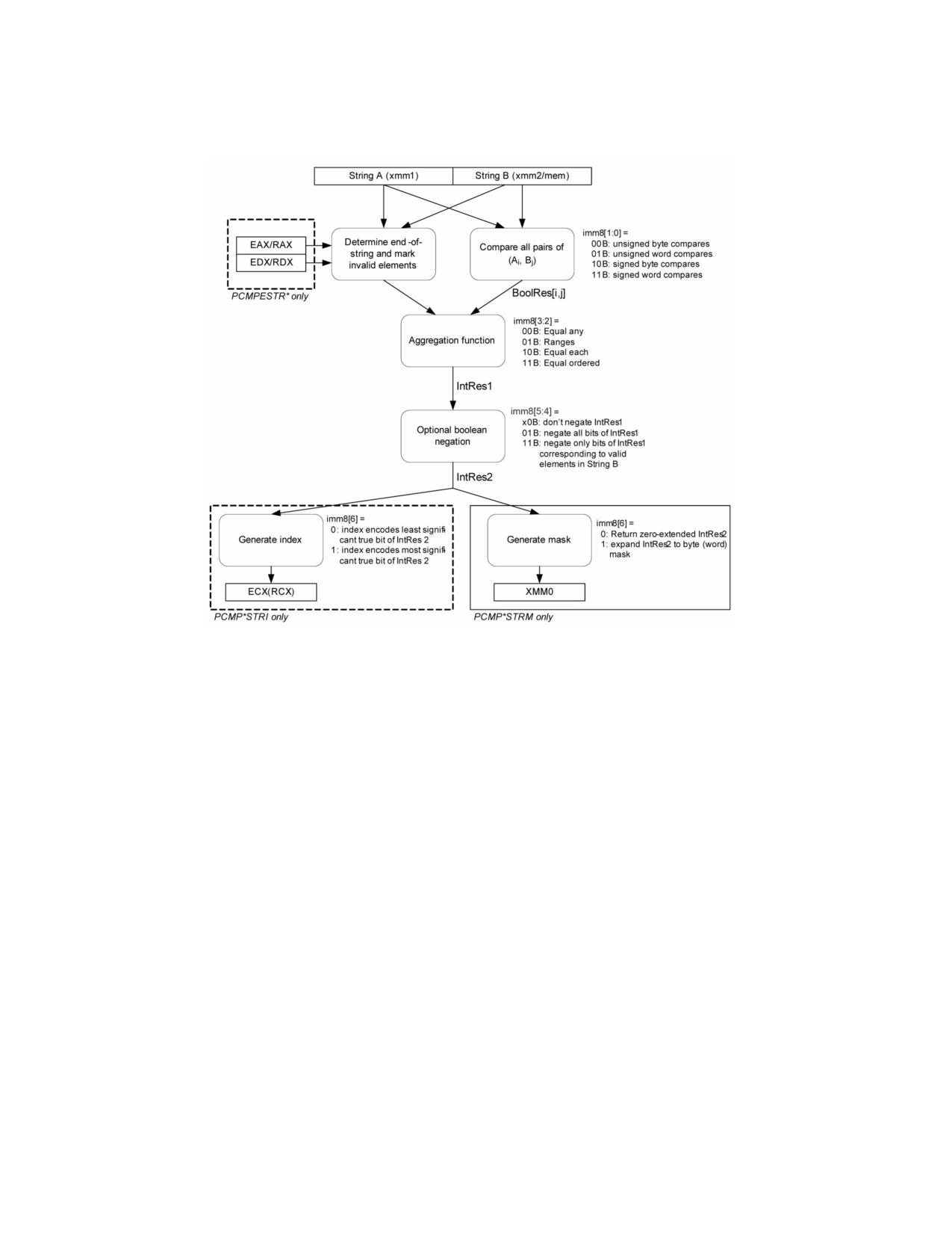
4.1.8
Diagram Comparison and Aggregation Process
Figure 4-1. Operation of PCMPSTRx and PCMPESTRx
4.2
COMMON TRANSFORMATION AND PRIMITIVE FUNCTIONS FOR SHA1XXX
AND SHA256XXX
The following primitive functions and transformations are used in the algorithmic descriptions of SHA1 and SHA256
instruction extensions SHA1NEXTE, SHA1RNDS4, SHA1MSG1, SHA1MSG2, SHA256RNDS4, SHA256MSG1, and
SHA256MSG2. The operands of these primitives and transformation are generally 32-bit DWORD integers.
• f0(): A bit oriented logical operation that derives a new dword from three SHA1 state variables (dword). This
function is used in SHA1 round 1 to 20 processing.
f0(B,C,D) := (B AND C) XOR ((NOT(B) AND D)
• f1(): A bit oriented logical operation that derives a new dword from three SHA1 state variables (dword). This
function is used in SHA1 round 21 to 40 processing.
f1(B,C,D) := B XOR C XOR D
• f2(): A bit oriented logical operation that derives a new dword from three SHA1 state variables (dword). This
function is used in SHA1 round 41 to 60 processing.
f2(B,C,D) := (B AND C) XOR (B AND D) XOR (C AND D)
• f3(): A bit oriented logical operation that derives a new dword from three SHA1 state variables (dword). This
function is used in SHA1 round 61 to 80 processing. It is the same as f1().
f3(B,C,D) := B XOR C XOR D
• Ch(): A bit oriented logical operation that derives a new dword from three SHA256 state variables (dword).
4-6
Vol. 2B
INSTRUCTION SET REFERENCE, M-U
Ch(E,F,G) := (E AND F) XOR ((NOT E) AND G)
• Maj(): A bit oriented logical operation that derives a new dword from three SHA256 state variables (dword).
Maj(A,B,C) := (A AND B) XOR (A AND C) XOR (B AND C)
ROR is rotate right operation
(A ROR N) := A[N-1:0] || A[Width-1:N]
ROL is rotate left operation
(A ROL N) := A ROR (Width-N)
SHR is the right shift operation
(A SHR N) := ZEROES[N-1:0] || A[Width-1:N]
• Σ0( ): A bit oriented logical and rotational transformation performed on a dword SHA256 state variable.
Σ0(A) := (A ROR 2) XOR (A ROR 13) XOR (A ROR 22)
• Σ1( ): A bit oriented logical and rotational transformation performed on a dword SHA256 state variable.
Σ1(E) := (E ROR 6) XOR (E ROR 11) XOR (E ROR 25)
• σ0( ): A bit oriented logical and rotational transformation performed on a SHA256 message dword used in the
message scheduling.
σ0(W) := (W ROR 7) XOR (W ROR 18) XOR (W SHR 3)
• σ1( ): A bit oriented logical and rotational transformation performed on a SHA256 message dword used in the
message scheduling.
σ1(W) := (W ROR 17) XOR (W ROR 19) XOR (W SHR 10)
• Ki: SHA1 Constants dependent on immediate i.
K0 = 0x5A827999
K1 = 0x6ED9EBA1
K2 = 0X8F1BBCDC
K3 = 0xCA62C1D6
4.3
INSTRUCTIONS (M-U)
Chapter 4 continues an alphabetical discussion of Intel® 64 and IA-32 instructions (M-U). See also: Chapter 3,
“Instruction Set Reference, A-L,” in the Intel® 64 and IA-32 Architectures Software Developer’s Manual, Volume
2A; Chapter 5, “Instruction Set Reference, V‚” in the Intel® 64 and IA-32 Architectures Software Developer’s
Manual, Volume 2C; and Chapter 6, “Instruction Set Reference, W-Z‚” in the Intel® 64 and IA-32 Architectures
Software Developer’s Manual, Volume 2D.
Vol. 2B
4-7
INSTRUCTION SET REFERENCE, M-U
MASKMOVDQU-Store Selected Bytes of Double Quadword
Opcode/
Op/
64/32-bit
CPUID
Description
Instruction
En
Mode
Feature
Flag
66 0F F7 /r
RM
V/V
SSE2
Selectively write bytes from xmm1 to memory location
using the byte mask in xmm2. The default memory location
MASKMOVDQU xmm1, xmm2
is specified by DS:DI/EDI/RDI.
VEX.128.66.0F.WIG F7 /r
RM
V/V
AVX
Selectively write bytes from xmm1 to memory location
using the byte mask in xmm2. The default memory location
VMASKMOVDQU xmm1, xmm2
is specified by DS:DI/EDI/RDI.
Instruction Operand Encoding1
Op/En
Operand 1
Operand 2
Operand 3
Operand 4
RM
ModRM:reg (r)
ModRM:r/m (r)
N/A
N/A
Description
Stores selected bytes from the source operand (first operand) into an 128-bit memory location. The mask operand
(second operand) selects which bytes from the source operand are written to memory. The source and mask oper-
ands are XMM registers. The memory location specified by the effective address in the DI/EDI/RDI register (the
default segment register is DS, but this may be overridden with a segment-override prefix). The memory location
does not need to be aligned on a natural boundary. (The size of the store address depends on the address-size
attribute.)
The most significant bit in each byte of the mask operand determines whether the corresponding byte in the source
operand is written to the corresponding byte location in memory: 0 indicates no write and 1 indicates write.
The MASKMOVDQU instruction generates a non-temporal hint to the processor to minimize cache pollution. The
non-temporal hint is implemented by using a write combining (WC) memory type protocol (see “Caching of
Temporal vs. Non-Temporal Data” in Chapter 10, of the Intel® 64 and IA-32 Architectures Software Developer’s
Manual, Volume 1). Because the WC protocol uses a weakly-ordered memory consistency model, a fencing opera-
tion implemented with the SFENCE or MFENCE instruction should be used in conjunction with MASKMOVDQU
instructions if multiple processors might use different memory types to read/write the destination memory loca-
tions.
Behavior with a mask of all 0s is as follows:
• No data will be written to memory.
• Signaling of breakpoints (code or data) is not guaranteed; different processor implementations may signal or
not signal these breakpoints.
• Exceptions associated with addressing memory and page faults may still be signaled (implementation
dependent).
• If the destination memory region is mapped as UC or WP, enforcement of associated semantics for these
memory types is not guaranteed (that is, is reserved) and is implementation-specific.
The MASKMOVDQU instruction can be used to improve performance of algorithms that need to merge data on a
byte-by-byte basis. MASKMOVDQU should not cause a read for ownership; doing so generates unnecessary band-
width since data is to be written directly using the byte-mask without allocating old data prior to the store.
In 64-bit mode, use of the REX.R prefix permits this instruction to access additional registers (XMM8-XMM15).
Note: In VEX-encoded versions, VEX.vvvv is reserved and must be 1111b otherwise instructions will #UD.
If VMASKMOVDQU is encoded with VEX.L= 1, an attempt to execute the instruction encoded with VEX.L= 1 will
cause an #UD exception.
1.ModRM.MOD = 011B required
4-8
Vol. 2B
MASKMOVDQU-Store Selected Bytes of Double Quadword
INSTRUCTION SET REFERENCE, M-U
Operation
IF (MASK[7] = 1)
THEN DEST[DI/EDI] := SRC[7:0] ELSE (* Memory location unchanged *); FI;
IF (MASK[15] = 1)
THEN DEST[DI/EDI +1] := SRC[15:8] ELSE (* Memory location unchanged *); FI;
(* Repeat operation for 3rd through 14th bytes in source operand *)
IF (MASK[127] = 1)
THEN DEST[DI/EDI +15] := SRC[127:120] ELSE (* Memory location unchanged *); FI;
Intel C/C++ Compiler Intrinsic Equivalent
void _mm_maskmoveu_si128(__m128i d, __m128i n, char * p)
Other Exceptions
See Table 2-21, “Type 4 Class Exception Conditions,” additionally:
#UD
If VEX.L= 1
If VEX.vvvv ≠ 1111B.
MASKMOVDQU-Store Selected Bytes of Double Quadword
Vol. 2B
4-9
INSTRUCTION SET REFERENCE, M-U
MASKMOVQ-Store Selected Bytes of Quadword
Opcode/
Op/
64-Bit
Compat/
Description
Instruction
En
Mode
Leg Mode
NP 0F F7 /r
RM
Valid
Valid
Selectively write bytes from mm1 to memory location using
the byte mask in mm2. The default memory location is
MASKMOVQ mm1, mm2
specified by DS:DI/EDI/RDI.
Instruction Operand Encoding
Op/En
Operand 1
Operand 2
Operand 3
Operand 4
RM
ModRM:reg (r)
ModRM:r/m (r)
N/A
N/A
Description
Stores selected bytes from the source operand (first operand) into a 64-bit memory location. The mask operand
(second operand) selects which bytes from the source operand are written to memory. The source and mask oper-
ands are MMX technology registers. The memory location specified by the effective address in the DI/EDI/RDI
register (the default segment register is DS, but this may be overridden with a segment-override prefix). The
memory location does not need to be aligned on a natural boundary. (The size of the store address depends on the
address-size attribute.)
The most significant bit in each byte of the mask operand determines whether the corresponding byte in the source
operand is written to the corresponding byte location in memory: 0 indicates no write and 1 indicates write.
The MASKMOVQ instruction generates a non-temporal hint to the processor to minimize cache pollution. The non-
temporal hint is implemented by using a write combining (WC) memory type protocol (see “Caching of Temporal
vs. Non-Temporal Data” in Chapter 10, of the Intel® 64 and IA-32 Architectures Software Developer’s Manual,
Volume 1). Because the WC protocol uses a weakly-ordered memory consistency model, a fencing operation imple-
mented with the SFENCE or MFENCE instruction should be used in conjunction with MASKMOVQ instructions if
multiple processors might use different memory types to read/write the destination memory locations.
This instruction causes a transition from x87 FPU to MMX technology state (that is, the x87 FPU top-of-stack pointer
is set to 0 and the x87 FPU tag word is set to all 0s [valid]).
The behavior of the MASKMOVQ instruction with a mask of all 0s is as follows:
• No data will be written to memory.
• Transition from x87 FPU to MMX technology state will occur.
• Exceptions associated with addressing memory and page faults may still be signaled (implementation
dependent).
• Signaling of breakpoints (code or data) is not guaranteed (implementation dependent).
• If the destination memory region is mapped as UC or WP, enforcement of associated semantics for these
memory types is not guaranteed (that is, is reserved) and is implementation-specific.
The MASKMOVQ instruction can be used to improve performance for algorithms that need to merge data on a byte-
by-byte basis. It should not cause a read for ownership; doing so generates unnecessary bandwidth since data is
to be written directly using the byte-mask without allocating old data prior to the store.
In 64-bit mode, the memory address is specified by DS:RDI.
Operation
IF (MASK[7] = 1)
THEN DEST[DI/EDI] := SRC[7:0] ELSE (* Memory location unchanged *); FI;
IF (MASK[15] = 1)
THEN DEST[DI/EDI +1] := SRC[15:8] ELSE (* Memory location unchanged *); FI;
(* Repeat operation for 3rd through 6th bytes in source operand *)
IF (MASK[63] = 1)
THEN DEST[DI/EDI +15] := SRC[63:56] ELSE (* Memory location unchanged *); FI;
4-10
Vol. 2B
MASKMOVQ-Store Selected Bytes of Quadword
INSTRUCTION SET REFERENCE, M-U
Intel C/C++ Compiler Intrinsic Equivalent
void _mm_maskmove_si64(__m64d, __m64n, char * p)
Other Exceptions
See Table 23-8, “Exception Conditions for Legacy SIMD/MMX Instructions without FP Exception,” in the Intel® 64
and IA-32 Architectures Software Developer’s Manual, Volume 3B.
MASKMOVQ-Store Selected Bytes of Quadword
Vol. 2B
4-11

INSTRUCTION SET REFERENCE, M-U
MAXPD-Maximum of Packed Double Precision Floating-Point Values
Opcode/
Op /
64/32 bit
CPUID
Description
Instruction
En
Mode
Feature
Support
Flag
66 0F 5F /r
A
V/V
SSE2
Return the maximum double precision floating-point
MAXPD xmm1, xmm2/m128
values between xmm1 and xmm2/m128.
VEX.128.66.0F.WIG 5F /r
B
V/V
AVX
Return the maximum double precision floating-point
VMAXPD xmm1, xmm2, xmm3/m128
values between xmm2 and xmm3/m128.
VEX.256.66.0F.WIG 5F /r
B
V/V
AVX
Return the maximum packed double precision floating-
VMAXPD ymm1, ymm2, ymm3/m256
point values between ymm2 and ymm3/m256.
EVEX.128.66.0F.W1 5F /r
C
V/V
AVX512VL
Return the maximum packed double precision floating-
VMAXPD xmm1 {k1}{z}, xmm2,
AVX512F
point values between xmm2 and xmm3/m128/m64bcst
xmm3/m128/m64bcst
and store result in xmm1 subject to writemask k1.
EVEX.256.66.0F.W1 5F /r
C
V/V
AVX512VL
Return the maximum packed double precision floating-
VMAXPD ymm1 {k1}{z}, ymm2,
AVX512F
point values between ymm2 and ymm3/m256/m64bcst
ymm3/m256/m64bcst
and store result in ymm1 subject to writemask k1.
EVEX.512.66.0F.W1 5F /r
C
V/V
AVX512F
Return the maximum packed double precision floating-
VMAXPD zmm1 {k1}{z}, zmm2,
point values between zmm2 and zmm3/m512/m64bcst
zmm3/m512/m64bcst{sae}
and store result in zmm1 subject to writemask k1.
Instruction Operand Encoding
Op/En
Tuple Type
Operand 1
Operand 2
Operand 3
Operand 4
A
N/A
ModRM:reg (r, w)
ModRM:r/m (r)
N/A
N/A
B
N/A
ModRM:reg (w)
VEX.vvvv (r)
ModRM:r/m (r)
N/A
C
Full
ModRM:reg (w)
EVEX.vvvv (r)
ModRM:r/m (r)
N/A
Description
Performs a SIMD compare of the packed double precision floating-point values in the first source operand and the
second source operand and returns the maximum value for each pair of values to the destination operand.
If the values being compared are both 0.0s (of either sign), the value in the second operand (source operand) is
returned. If a value in the second operand is an SNaN, then SNaN is forwarded unchanged to the destination (that
is, a QNaN version of the SNaN is not returned).
If only one value is a NaN (SNaN or QNaN) for this instruction, the second operand (source operand), either a NaN
or a valid floating-point value, is written to the result. If instead of this behavior, it is required that the NaN source
operand (from either the first or second operand) be returned, the action of MAXPD can be emulated using a
sequence of instructions, such as a comparison followed by AND, ANDN, and OR.
EVEX encoded versions: The first source operand (the second operand) is a ZMM/YMM/XMM register. The second
source operand can be a ZMM/YMM/XMM register, a 512/256/128-bit memory location or a 512/256/128-bit vector
broadcasted from a 64-bit memory location. The destination operand is a ZMM/YMM/XMM register conditionally
updated with writemask k1.
VEX.256 encoded version: The first source operand is a YMM register. The second source operand can be a YMM
register or a 256-bit memory location. The destination operand is a YMM register. The upper bits (MAXVL-1:256) of
the corresponding ZMM register destination are zeroed.
VEX.128 encoded version: The first source operand is a XMM register. The second source operand can be a XMM
register or a 128-bit memory location. The destination operand is a XMM register. The upper bits (MAXVL-1:128) of
the corresponding ZMM register destination are zeroed.
128-bit Legacy SSE version: The second source can be an XMM register or an 128-bit memory location. The desti-
nation is not distinct from the first source XMM register and the upper bits (MAXVL-1:128) of the corresponding
ZMM register destination are unmodified.
4-12
Vol. 2B
MAXPD-Maximum of Packed Double Precision Floating-Point Values
INSTRUCTION SET REFERENCE, M-U
Operation
MAX(SRC1, SRC2)
{
IF ((SRC1 = 0.0) and (SRC2 = 0.0)) THEN DEST := SRC2;
ELSE IF (SRC1 = NaN) THEN DEST := SRC2; FI;
ELSE IF (SRC2 = NaN) THEN DEST := SRC2; FI;
ELSE IF (SRC1 > SRC2) THEN DEST := SRC1;
ELSE DEST := SRC2;
FI;
}
VMAXPD (EVEX Encoded Versions)
(KL, VL) = (2, 128), (4, 256), (8, 512)
FOR j := 0 TO KL-1
i := j * 64
IF k1[j] OR *no writemask*
THEN
IF (EVEX.b = 1) AND (SRC2 *is memory*)
THEN
DEST[i+63:i] := MAX(SRC1[i+63:i], SRC2[63:0])
ELSE
DEST[i+63:i] := MAX(SRC1[i+63:i], SRC2[i+63:i])
FI;
ELSE
IF *merging-masking*
; merging-masking
THEN *DEST[i+63:i] remains unchanged*
ELSE DEST[i+63:i] := 0
; zeroing-masking
FI
FI;
ENDFOR
DEST[MAXVL-1:VL] := 0
VMAXPD (VEX.256 Encoded Version)
DEST[63:0] := MAX(SRC1[63:0], SRC2[63:0])
DEST[127:64] := MAX(SRC1[127:64], SRC2[127:64])
DEST[191:128] := MAX(SRC1[191:128], SRC2[191:128])
DEST[255:192] := MAX(SRC1[255:192], SRC2[255:192])
DEST[MAXVL-1:256] := 0
VMAXPD (VEX.128 Encoded Version)
DEST[63:0] := MAX(SRC1[63:0], SRC2[63:0])
DEST[127:64] := MAX(SRC1[127:64], SRC2[127:64])
DEST[MAXVL-1:128] := 0
MAXPD (128-bit Legacy SSE Version)
DEST[63:0] := MAX(DEST[63:0], SRC[63:0])
DEST[127:64] := MAX(DEST[127:64], SRC[127:64])
DEST[MAXVL-1:128] (Unmodified)
MAXPD-Maximum of Packed Double Precision Floating-Point Values
Vol. 2B
4-13
INSTRUCTION SET REFERENCE, M-U
Intel C/C++ Compiler Intrinsic Equivalent
VMAXPD __m512d _mm512_max_pd( __m512d a, __m512d b);
VMAXPD __m512d _mm512_mask_max_pd(__m512d s, __mmask8 k, __m512d a, __m512d b,);
VMAXPD __m512d _mm512_maskz_max_pd( __mmask8 k, __m512d a, __m512d b);
VMAXPD __m512d _mm512_max_round_pd( __m512d a, __m512d b, int);
VMAXPD __m512d _mm512_mask_max_round_pd(__m512d s, __mmask8 k, __m512d a, __m512d b, int);
VMAXPD __m512d _mm512_maskz_max_round_pd( __mmask8 k, __m512d a, __m512d b, int);
VMAXPD __m256d _mm256_mask_max_pd(__m5256d s, __mmask8 k, __m256d a, __m256d b);
VMAXPD __m256d _mm256_maskz_max_pd( __mmask8 k, __m256d a, __m256d b);
VMAXPD __m128d _mm_mask_max_pd(__m128d s, __mmask8 k, __m128d a, __m128d b);
VMAXPD __m128d _mm_maskz_max_pd( __mmask8 k, __m128d a, __m128d b);
VMAXPD __m256d _mm256_max_pd (__m256d a, __m256d b);
(V)MAXPD __m128d _mm_max_pd (__m128d a, __m128d b);
SIMD Floating-Point Exceptions
Invalid (including QNaN Source Operand), Denormal.
Other Exceptions
Non-EVEX-encoded instruction, see Table 2-19, “Type 2 Class Exception Conditions.”
EVEX-encoded instruction, see Table 2-46, “Type E2 Class Exception Conditions.”
4-14
Vol. 2B
MAXPD-Maximum of Packed Double Precision Floating-Point Values

INSTRUCTION SET REFERENCE, M-U
MAXPS-Maximum of Packed Single Precision Floating-Point Values
Opcode/
Op /
64/32 bit
CPUID
Description
Instruction
En
Mode
Feature
Support
Flag
NP 0F 5F /r
A
V/V
SSE
Return the maximum single precision floating-point values
MAXPS xmm1, xmm2/m128
between xmm1 and xmm2/mem.
VEX.128.0F.WIG 5F /r
B
V/V
AVX
Return the maximum single precision floating-point values
VMAXPS xmm1, xmm2,
between xmm2 and xmm3/mem.
xmm3/m128
VEX.256.0F.WIG 5F /r
B
V/V
AVX
Return the maximum single precision floating-point values
VMAXPS ymm1, ymm2,
between ymm2 and ymm3/mem.
ymm3/m256
EVEX.128.0F.W0 5F /r
C
V/V
AVX512VL
Return the maximum packed single precision floating-point
VMAXPS xmm1 {k1}{z}, xmm2,
AVX512F
values between xmm2 and xmm3/m128/m32bcst and store
xmm3/m128/m32bcst
result in xmm1 subject to writemask k1.
EVEX.256.0F.W0 5F /r
C
V/V
AVX512VL
Return the maximum packed single precision floating-point
VMAXPS ymm1 {k1}{z}, ymm2,
AVX512F
values between ymm2 and ymm3/m256/m32bcst and store
ymm3/m256/m32bcst
result in ymm1 subject to writemask k1.
EVEX.512.0F.W0 5F /r
C
V/V
AVX512F
Return the maximum packed single precision floating-point
VMAXPS zmm1 {k1}{z}, zmm2,
values between zmm2 and zmm3/m512/m32bcst and store
zmm3/m512/m32bcst{sae}
result in zmm1 subject to writemask k1.
Instruction Operand Encoding
Op/En
Tuple Type
Operand 1
Operand 2
Operand 3
Operand 4
A
N/A
ModRM:reg (r, w)
ModRM:r/m (r)
N/A
N/A
B
N/A
ModRM:reg (w)
VEX.vvvv (r)
ModRM:r/m (r)
N/A
C
Full
ModRM:reg (w)
EVEX.vvvv (r)
ModRM:r/m (r)
N/A
Description
Performs a SIMD compare of the packed single precision floating-point values in the first source operand and the
second source operand and returns the maximum value for each pair of values to the destination operand.
If the values being compared are both 0.0s (of either sign), the value in the second operand (source operand) is
returned. If a value in the second operand is an SNaN, then SNaN is forwarded unchanged to the destination (that
is, a QNaN version of the SNaN is not returned).
If only one value is a NaN (SNaN or QNaN) for this instruction, the second operand (source operand), either a NaN
or a valid floating-point value, is written to the result. If instead of this behavior, it is required that the NaN source
operand (from either the first or second operand) be returned, the action of MAXPS can be emulated using a
sequence of instructions, such as, a comparison followed by AND, ANDN, and OR.
EVEX encoded versions: The first source operand (the second operand) is a ZMM/YMM/XMM register. The second
source operand can be a ZMM/YMM/XMM register, a 512/256/128-bit memory location or a 512/256/128-bit vector
broadcasted from a 32-bit memory location. The destination operand is a ZMM/YMM/XMM register conditionally
updated with writemask k1.
VEX.256 encoded version: The first source operand is a YMM register. The second source operand can be a YMM
register or a 256-bit memory location. The destination operand is a YMM register. The upper bits (MAXVL-1:256) of
the corresponding ZMM register destination are zeroed.
VEX.128 encoded version: The first source operand is a XMM register. The second source operand can be a XMM
register or a 128-bit memory location. The destination operand is a XMM register. The upper bits (MAXVL-1:128) of
the corresponding ZMM register destination are zeroed.
MAXPS-Maximum of Packed Single Precision Floating-Point Values
Vol. 2B
4-15
INSTRUCTION SET REFERENCE, M-U
128-bit Legacy SSE version: The second source can be an XMM register or an 128-bit memory location. The desti-
nation is not distinct from the first source XMM register and the upper bits (MAXVL-1:128) of the corresponding
ZMM register destination are unmodified.
Operation
MAX(SRC1, SRC2)
{
IF ((SRC1 = 0.0) and (SRC2 = 0.0)) THEN DEST := SRC2;
ELSE IF (SRC1 = NaN) THEN DEST := SRC2; FI;
ELSE IF (SRC2 = NaN) THEN DEST := SRC2; FI;
ELSE IF (SRC1 > SRC2) THEN DEST := SRC1;
ELSE DEST := SRC2;
FI;
}
VMAXPS (EVEX Encoded Versions)
(KL, VL) = (4, 128), (8, 256), (16, 512)
FOR j := 0 TO KL-1
i := j * 32
IF k1[j] OR *no writemask*
THEN
IF (EVEX.b = 1) AND (SRC2 *is memory*)
THEN
DEST[i+31:i] := MAX(SRC1[i+31:i], SRC2[31:0])
ELSE
DEST[i+31:i] := MAX(SRC1[i+31:i], SRC2[i+31:i])
FI;
ELSE
IF *merging-masking*
; merging-masking
THEN *DEST[i+31:i] remains unchanged*
ELSE DEST[i+31:i] := 0
; zeroing-masking
FI
FI;
ENDFOR
DEST[MAXVL-1:VL] := 0
VMAXPS (VEX.256 Encoded Version)
DEST[31:0] := MAX(SRC1[31:0], SRC2[31:0])
DEST[63:32] := MAX(SRC1[63:32], SRC2[63:32])
DEST[95:64] := MAX(SRC1[95:64], SRC2[95:64])
DEST[127:96] := MAX(SRC1[127:96], SRC2[127:96])
DEST[159:128] := MAX(SRC1[159:128], SRC2[159:128])
DEST[191:160] := MAX(SRC1[191:160], SRC2[191:160])
DEST[223:192] := MAX(SRC1[223:192], SRC2[223:192])
DEST[255:224] := MAX(SRC1[255:224], SRC2[255:224])
DEST[MAXVL-1:256] := 0
VMAXPS (VEX.128 Encoded Version)
DEST[31:0] := MAX(SRC1[31:0], SRC2[31:0])
DEST[63:32] := MAX(SRC1[63:32], SRC2[63:32])
DEST[95:64] := MAX(SRC1[95:64], SRC2[95:64])
DEST[127:96] := MAX(SRC1[127:96], SRC2[127:96])
DEST[MAXVL-1:128] := 0
4-16
Vol. 2B
MAXPS-Maximum of Packed Single Precision Floating-Point Values
INSTRUCTION SET REFERENCE, M-U
MAXPS (128-bit Legacy SSE Version)
DEST[31:0] := MAX(DEST[31:0], SRC[31:0])
DEST[63:32] := MAX(DEST[63:32], SRC[63:32])
DEST[95:64] := MAX(DEST[95:64], SRC[95:64])
DEST[127:96] := MAX(DEST[127:96], SRC[127:96])
DEST[MAXVL-1:128] (Unmodified)
Intel C/C++ Compiler Intrinsic Equivalent
VMAXPS __m512 _mm512_max_ps( __m512 a, __m512 b);
VMAXPS __m512 _mm512_mask_max_ps(__m512 s, __mmask16 k, __m512 a, __m512 b);
VMAXPS __m512 _mm512_maskz_max_ps( __mmask16 k, __m512 a, __m512 b);
VMAXPS __m512 _mm512_max_round_ps( __m512 a, __m512 b, int);
VMAXPS __m512 _mm512_mask_max_round_ps(__m512 s, __mmask16 k, __m512 a, __m512 b, int);
VMAXPS __m512 _mm512_maskz_max_round_ps( __mmask16 k, __m512 a, __m512 b, int);
VMAXPS __m256 _mm256_mask_max_ps(__m256 s, __mmask8 k, __m256 a, __m256 b);
VMAXPS __m256 _mm256_maskz_max_ps( __mmask8 k, __m256 a, __m256 b);
VMAXPS __m128 _mm_mask_max_ps(__m128 s, __mmask8 k, __m128 a, __m128 b);
VMAXPS __m128 _mm_maskz_max_ps( __mmask8 k, __m128 a, __m128 b);
VMAXPS __m256 _mm256_max_ps (__m256 a, __m256 b);
MAXPS __m128 _mm_max_ps (__m128 a, __m128 b);
SIMD Floating-Point Exceptions
Invalid (including QNaN Source Operand), Denormal.
Other Exceptions
Non-EVEX-encoded instruction, see Table 2-19, “Type 2 Class Exception Conditions.”
EVEX-encoded instruction, see Table 2-46, “Type E2 Class Exception Conditions.”
MAXPS-Maximum of Packed Single Precision Floating-Point Values
Vol. 2B
4-17
INSTRUCTION SET REFERENCE, M-U
MAXSD-Return Maximum Scalar Double Precision Floating-Point Value
Opcode/
Op /
64/32 bit
CPUID
Description
Instruction
En
Mode
Feature
Support
Flag
F2 0F 5F /r
A
V/V
SSE2
Return the maximum scalar double precision floating-
MAXSD xmm1, xmm2/m64
point value between xmm2/m64 and xmm1.
VEX.LIG.F2.0F.WIG 5F /r
B
V/V
AVX
Return the maximum scalar double precision floating-
VMAXSD xmm1, xmm2, xmm3/m64
point value between xmm3/m64 and xmm2.
EVEX.LLIG.F2.0F.W1 5F /r
C
V/V
AVX512F
Return the maximum scalar double precision floating-
VMAXSD xmm1 {k1}{z}, xmm2,
point value between xmm3/m64 and xmm2.
xmm3/m64{sae}
Instruction Operand Encoding
Op/En
Tuple Type
Operand 1
Operand 2
Operand 3
Operand 4
A
N/A
ModRM:reg (r, w)
ModRM:r/m (r)
N/A
N/A
B
N/A
ModRM:reg (w)
VEX.vvvv (r)
ModRM:r/m (r)
N/A
C
Tuple1 Scalar
ModRM:reg (w)
EVEX.vvvv (r)
ModRM:r/m (r)
N/A
Description
Compares the low double precision floating-point values in the first source operand and the second source operand,
and returns the maximum value to the low quadword of the destination operand. The second source operand can
be an XMM register or a 64-bit memory location. The first source and destination operands are XMM registers.
When the second source operand is a memory operand, only 64 bits are accessed.
If the values being compared are both 0.0s (of either sign), the value in the second source operand is returned. If
a value in the second source operand is an SNaN, that SNaN is returned unchanged to the destination (that is, a
QNaN version of the SNaN is not returned).
If only one value is a NaN (SNaN or QNaN) for this instruction, the second source operand, either a NaN or a valid
floating-point value, is written to the result. If instead of this behavior, it is required that the NaN of either source
operand be returned, the action of MAXSD can be emulated using a sequence of instructions, such as, a comparison
followed by AND, ANDN, and OR.
128-bit Legacy SSE version: The destination and first source operand are the same. Bits (MAXVL-1:64) of the
corresponding destination register remain unchanged.
VEX.128 and EVEX encoded version: Bits (127:64) of the XMM register destination are copied from corresponding
bits in the first source operand. Bits (MAXVL-1:128) of the destination register are zeroed.
EVEX encoded version: The low quadword element of the destination operand is updated according to the
writemask.
Software should ensure VMAXSD is encoded with VEX.L=0. Encoding VMAXSD with VEX.L=1 may encounter unpre-
dictable behavior across different processor generations.
Operation
MAX(SRC1, SRC2)
{
IF ((SRC1 = 0.0) and (SRC2 = 0.0)) THEN DEST := SRC2;
ELSE IF (SRC1 = NaN) THEN DEST := SRC2; FI;
ELSE IF (SRC2 = NaN) THEN DEST := SRC2; FI;
ELSE IF (SRC1 > SRC2) THEN DEST := SRC1;
ELSE DEST := SRC2;
FI;
}
4-18
Vol. 2B
MAXSD-Return Maximum Scalar Double Precision Floating-Point Value
INSTRUCTION SET REFERENCE, M-U
VMAXSD (EVEX Encoded Version)
IF k1[0] or *no writemask*
THEN
DEST[63:0] := MAX(SRC1[63:0], SRC2[63:0])
ELSE
IF *merging-masking*
; merging-masking
THEN *DEST[63:0] remains unchanged*
ELSE
; zeroing-masking
DEST[63:0] := 0
FI;
FI;
DEST[127:64] := SRC1[127:64]
DEST[MAXVL-1:128] := 0
VMAXSD (VEX.128 Encoded Version)
DEST[63:0] := MAX(SRC1[63:0], SRC2[63:0])
DEST[127:64] := SRC1[127:64]
DEST[MAXVL-1:128] := 0
MAXSD (128-bit Legacy SSE Version)
DEST[63:0] := MAX(DEST[63:0], SRC[63:0])
DEST[MAXVL-1:64] (Unmodified)
Intel C/C++ Compiler Intrinsic Equivalent
VMAXSD __m128d _mm_max_round_sd( __m128d a, __m128d b, int);
VMAXSD __m128d _mm_mask_max_round_sd(__m128d s, __mmask8 k, __m128d a, __m128d b, int);
VMAXSD __m128d _mm_maskz_max_round_sd( __mmask8 k, __m128d a, __m128d b, int);
MAXSD __m128d _mm_max_sd(__m128d a, __m128d b)
SIMD Floating-Point Exceptions
Invalid (Including QNaN Source Operand), Denormal.
Other Exceptions
Non-EVEX-encoded instruction, see Table 2-20, “Type 3 Class Exception Conditions.”
EVEX-encoded instruction, see Table 2-47, “Type E3 Class Exception Conditions.”
MAXSD-Return Maximum Scalar Double Precision Floating-Point Value
Vol. 2B
4-19
INSTRUCTION SET REFERENCE, M-U
MAXSS-Return Maximum Scalar Single Precision Floating-Point Value
Opcode/
Op /
64/32 bit
CPUID
Description
Instruction
En
Mode
Feature
Support
Flag
F3 0F 5F /r
A
V/V
SSE
Return the maximum scalar single precision floating-point
MAXSS xmm1, xmm2/m32
value between xmm2/m32 and xmm1.
VEX.LIG.F3.0F.WIG 5F /r
B
V/V
AVX
Return the maximum scalar single precision floating-point
VMAXSS xmm1, xmm2, xmm3/m32
value between xmm3/m32 and xmm2.
EVEX.LLIG.F3.0F.W0 5F /r
C
V/V
AVX512F
Return the maximum scalar single precision floating-point
VMAXSS xmm1 {k1}{z}, xmm2,
value between xmm3/m32 and xmm2.
xmm3/m32{sae}
Instruction Operand Encoding
Op/En
Tuple Type
Operand 1
Operand 2
Operand 3
Operand 4
A
N/A
ModRM:reg (r, w)
ModRM:r/m (r)
N/A
N/A
B
N/A
ModRM:reg (w)
VEX.vvvv (r)
ModRM:r/m (r)
N/A
C
Tuple1 Scalar
ModRM:reg (w)
EVEX.vvvv (r)
ModRM:r/m (r)
N/A
Description
Compares the low single precision floating-point values in the first source operand and the second source operand,
and returns the maximum value to the low doubleword of the destination operand.
If the values being compared are both 0.0s (of either sign), the value in the second source operand is returned. If
a value in the second source operand is an SNaN, that SNaN is returned unchanged to the destination (that is, a
QNaN version of the SNaN is not returned).
If only one value is a NaN (SNaN or QNaN) for this instruction, the second source operand, either a NaN or a valid
floating-point value, is written to the result. If instead of this behavior, it is required that the NaN from either source
operand be returned, the action of MAXSS can be emulated using a sequence of instructions, such as, a comparison
followed by AND, ANDN, and OR.
The second source operand can be an XMM register or a 32-bit memory location. The first source and destination
operands are XMM registers.
128-bit Legacy SSE version: The destination and first source operand are the same. Bits (MAXVL:32) of the corre-
sponding destination register remain unchanged.
VEX.128 and EVEX encoded version: The first source operand is an xmm register encoded by VEX.vvvv. Bits
(127:32) of the XMM register destination are copied from corresponding bits in the first source operand. Bits
(MAXVL:128) of the destination register are zeroed.
EVEX encoded version: The low doubleword element of the destination operand is updated according to the
writemask.
Software should ensure VMAXSS is encoded with VEX.L=0. Encoding VMAXSS with VEX.L=1 may encounter unpre-
dictable behavior across different processor generations.
Operation
MAX(SRC1, SRC2)
{
IF ((SRC1 = 0.0) and (SRC2 = 0.0)) THEN DEST := SRC2;
ELSE IF (SRC1 = NaN) THEN DEST := SRC2; FI;
ELSE IF (SRC2 = NaN) THEN DEST := SRC2; FI;
ELSE IF (SRC1 > SRC2) THEN DEST := SRC1;
ELSE DEST := SRC2;
FI;
4-20
Vol. 2B
MAXSS-Return Maximum Scalar Single Precision Floating-Point Value
INSTRUCTION SET REFERENCE, M-U
}
VMAXSS (EVEX Encoded Version)
IF k1[0] or *no writemask*
THEN
DEST[31:0] := MAX(SRC1[31:0], SRC2[31:0])
ELSE
IF *merging-masking*
; merging-masking
THEN *DEST[31:0] remains unchanged*
ELSE
; zeroing-masking
THEN DEST[31:0] := 0
FI;
FI;
DEST[127:32] := SRC1[127:32]
DEST[MAXVL-1:128] := 0
VMAXSS (VEX.128 Encoded Version)
DEST[31:0] := MAX(SRC1[31:0], SRC2[31:0])
DEST[127:32] := SRC1[127:32]
DEST[MAXVL-1:128] := 0
MAXSS (128-bit Legacy SSE Version)
DEST[31:0] := MAX(DEST[31:0], SRC[31:0])
DEST[MAXVL-1:32] (Unmodified)
Intel C/C++ Compiler Intrinsic Equivalent
VMAXSS __m128 _mm_max_round_ss( __m128 a, __m128 b, int);
VMAXSS __m128 _mm_mask_max_round_ss(__m128 s, __mmask8 k, __m128 a, __m128 b, int);
VMAXSS __m128 _mm_maskz_max_round_ss( __mmask8 k, __m128 a, __m128 b, int);
MAXSS __m128 _mm_max_ss(__m128 a, __m128 b)
SIMD Floating-Point Exceptions
Invalid (Including QNaN Source Operand), Denormal.
Other Exceptions
Non-EVEX-encoded instruction, see Table 2-20, “Type 3 Class Exception Conditions.”
EVEX-encoded instruction, see Table 2-47, “Type E3 Class Exception Conditions.”
MAXSS-Return Maximum Scalar Single Precision Floating-Point Value
Vol. 2B
4-21
INSTRUCTION SET REFERENCE, M-U
MFENCE-Memory Fence
Opcode /
Op/
64/32 bit
CPUID
Description
Instruction
En
Mode
Feature
Support
Flag
NP 0F AE F0
ZO
V/V
SSE2
Serializes load and store operations.
MFENCE
Instruction Operand Encoding
Op/En
Operand 1
Operand 2
Operand 3
Operand 4
ZO
N/A
N/A
N/A
N/A
Description
Performs a serializing operation on all load-from-memory and store-to-memory instructions that were issued prior
the MFENCE instruction. This serializing operation guarantees that every load and store instruction that precedes
the MFENCE instruction in program order becomes globally visible before any load or store instruction that follows
the MFENCE instruction.1 The MFENCE instruction is ordered with respect to all load and store instructions, other
MFENCE instructions, any LFENCE and SFENCE instructions, and any serializing instructions (such as the CPUID
instruction). MFENCE does not serialize the instruction stream.
Weakly ordered memory types can be used to achieve higher processor performance through such techniques as
out-of-order issue, speculative reads, write-combining, and write-collapsing. The degree to which a consumer of
data recognizes or knows that the data is weakly ordered varies among applications and may be unknown to the
producer of this data. The MFENCE instruction provides a performance-efficient way of ensuring load and store
ordering between routines that produce weakly-ordered results and routines that consume that data.
Processors are free to fetch and cache data speculatively from regions of system memory that use the WB, WC, and
WT memory types. This speculative fetching can occur at any time and is not tied to instruction execution. Thus, it
is not ordered with respect to executions of the MFENCE instruction; data can be brought into the caches specula-
tively just before, during, or after the execution of an MFENCE instruction.
This instruction’s operation is the same in non-64-bit modes and 64-bit mode.
Specification of the instruction's opcode above indicates a ModR/M byte of F0. For this instruction, the processor
ignores the r/m field of the ModR/M byte. Thus, MFENCE is encoded by any opcode of the form 0F AE Fx, where x
is in the range 0-7.
Operation
Wait_On_Following_Loads_And_Stores_Until(preceding_loads_and_stores_globally_visible);
Intel C/C++ Compiler Intrinsic Equivalent
void _mm_mfence(void)
Exceptions (All Modes of Operation)
#UD
If CPUID.01H:EDX.SSE2[bit 26] = 0.
If the LOCK prefix is used.
1. A load instruction is considered to become globally visible when the value to be loaded into its destination register is determined.
4-22
Vol. 2B
MFENCE-Memory Fence

INSTRUCTION SET REFERENCE, M-U
MINPD-Minimum of Packed Double Precision Floating-Point Values
Opcode/
Op /
64/32 bit
CPUID
Description
Instruction
En
Mode
Feature
Support
Flag
66 0F 5D /r
A
V/V
SSE2
Return the minimum double precision floating-point values
MINPD xmm1, xmm2/m128
between xmm1 and xmm2/mem
VEX.128.66.0F.WIG 5D /r
B
V/V
AVX
Return the minimum double precision floating-point values
VMINPD xmm1, xmm2,
between xmm2 and xmm3/mem.
xmm3/m128
VEX.256.66.0F.WIG 5D /r
B
V/V
AVX
Return the minimum packed double precision floating-point
VMINPD ymm1, ymm2,
values between ymm2 and ymm3/mem.
ymm3/m256
EVEX.128.66.0F.W1 5D /r
C
V/V
AVX512VL
Return the minimum packed double precision floating-point
VMINPD xmm1 {k1}{z}, xmm2,
AVX512F
values between xmm2 and xmm3/m128/m64bcst and store
xmm3/m128/m64bcst
result in xmm1 subject to writemask k1.
EVEX.256.66.0F.W1 5D /r
C
V/V
AVX512VL
Return the minimum packed double precision floating-point
VMINPD ymm1 {k1}{z}, ymm2,
AVX512F
values between ymm2 and ymm3/m256/m64bcst and store
ymm3/m256/m64bcst
result in ymm1 subject to writemask k1.
EVEX.512.66.0F.W1 5D /r
C
V/V
AVX512F
Return the minimum packed double precision floating-point
VMINPD zmm1 {k1}{z}, zmm2,
values between zmm2 and zmm3/m512/m64bcst and store
zmm3/m512/m64bcst{sae}
result in zmm1 subject to writemask k1.
Instruction Operand Encoding
Op/En
Tuple Type
Operand 1
Operand 2
Operand 3
Operand 4
A
N/A
ModRM:reg (r, w)
ModRM:r/m (r)
N/A
N/A
B
N/A
ModRM:reg (w)
VEX.vvvv (r)
ModRM:r/m (r)
N/A
C
Full
ModRM:reg (w)
EVEX.vvvv (r)
ModRM:r/m (r)
N/A
Description
Performs a SIMD compare of the packed double precision floating-point values in the first source operand and the
second source operand and returns the minimum value for each pair of values to the destination operand.
If the values being compared are both 0.0s (of either sign), the value in the second operand (source operand) is
returned. If a value in the second operand is an SNaN, then SNaN is forwarded unchanged to the destination (that
is, a QNaN version of the SNaN is not returned).
If only one value is a NaN (SNaN or QNaN) for this instruction, the second operand (source operand), either a NaN
or a valid floating-point value, is written to the result. If instead of this behavior, it is required that the NaN source
operand (from either the first or second operand) be returned, the action of MINPD can be emulated using a
sequence of instructions, such as, a comparison followed by AND, ANDN, and OR.
EVEX encoded versions: The first source operand (the second operand) is a ZMM/YMM/XMM register. The second
source operand can be a ZMM/YMM/XMM register, a 512/256/128-bit memory location or a 512/256/128-bit vector
broadcasted from a 64-bit memory location. The destination operand is a ZMM/YMM/XMM register conditionally
updated with writemask k1.
VEX.256 encoded version: The first source operand is a YMM register. The second source operand can be a YMM
register or a 256-bit memory location. The destination operand is a YMM register. The upper bits (MAXVL-1:256) of
the corresponding ZMM register destination are zeroed.
VEX.128 encoded version: The first source operand is a XMM register. The second source operand can be a XMM
register or a 128-bit memory location. The destination operand is a XMM register. The upper bits (MAXVL-1:128) of
the corresponding ZMM register destination are zeroed.
MINPD-Minimum of Packed Double Precision Floating-Point Values
Vol. 2B
4-23
INSTRUCTION SET REFERENCE, M-U
128-bit Legacy SSE version: The second source can be an XMM register or an 128-bit memory location. The desti-
nation is not distinct from the first source XMM register and the upper bits (MAXVL-1:128) of the corresponding
ZMM register destination are unmodified.
Operation
MIN(SRC1, SRC2)
{
IF ((SRC1 = 0.0) and (SRC2 = 0.0)) THEN DEST := SRC2;
ELSE IF (SRC1 = NaN) THEN DEST := SRC2; FI;
ELSE IF (SRC2 = NaN) THEN DEST := SRC2; FI;
ELSE IF (SRC1 < SRC2) THEN DEST := SRC1;
ELSE DEST := SRC2;
FI;
}
VMINPD (EVEX Encoded Version)
(KL, VL) = (2, 128), (4, 256), (8, 512)
FOR j := 0 TO KL-1
i := j * 64
IF k1[j] OR *no writemask*
THEN
IF (EVEX.b = 1) AND (SRC2 *is memory*)
THEN
DEST[i+63:i] := MIN(SRC1[i+63:i], SRC2[63:0])
ELSE
DEST[i+63:i] := MIN(SRC1[i+63:i], SRC2[i+63:i])
FI;
ELSE
IF *merging-masking*
; merging-masking
THEN *DEST[i+63:i] remains unchanged*
ELSE DEST[i+63:i] := 0
; zeroing-masking
FI
FI;
ENDFOR
DEST[MAXVL-1:VL] := 0
VMINPD (VEX.256 Encoded Version)
DEST[63:0] := MIN(SRC1[63:0], SRC2[63:0])
DEST[127:64] := MIN(SRC1[127:64], SRC2[127:64])
DEST[191:128] := MIN(SRC1[191:128], SRC2[191:128])
DEST[255:192] := MIN(SRC1[255:192], SRC2[255:192])
VMINPD (VEX.128 Encoded Version)
DEST[63:0] := MIN(SRC1[63:0], SRC2[63:0])
DEST[127:64] := MIN(SRC1[127:64], SRC2[127:64])
DEST[MAXVL-1:128] := 0
MINPD (128-bit Legacy SSE Version)
DEST[63:0] := MIN(SRC1[63:0], SRC2[63:0])
DEST[127:64] := MIN(SRC1[127:64], SRC2[127:64])
DEST[MAXVL-1:128] (Unmodified)
4-24
Vol. 2B
MINPD-Minimum of Packed Double Precision Floating-Point Values
INSTRUCTION SET REFERENCE, M-U
Intel C/C++ Compiler Intrinsic Equivalent
VMINPD __m512d _mm512_min_pd( __m512d a, __m512d b);
VMINPD __m512d _mm512_mask_min_pd(__m512d s, __mmask8 k, __m512d a, __m512d b);
VMINPD __m512d _mm512_maskz_min_pd( __mmask8 k, __m512d a, __m512d b);
VMINPD __m512d _mm512_min_round_pd( __m512d a, __m512d b, int);
VMINPD __m512d _mm512_mask_min_round_pd(__m512d s, __mmask8 k, __m512d a, __m512d b, int);
VMINPD __m512d _mm512_maskz_min_round_pd( __mmask8 k, __m512d a, __m512d b, int);
VMINPD __m256d _mm256_mask_min_pd(__m256d s, __mmask8 k, __m256d a, __m256d b);
VMINPD __m256d _mm256_maskz_min_pd( __mmask8 k, __m256d a, __m256d b);
VMINPD __m128d _mm_mask_min_pd(__m128d s, __mmask8 k, __m128d a, __m128d b);
VMINPD __m128d _mm_maskz_min_pd( __mmask8 k, __m128d a, __m128d b);
VMINPD __m256d _mm256_min_pd (__m256d a, __m256d b);
MINPD __m128d _mm_min_pd (__m128d a, __m128d b);
SIMD Floating-Point Exceptions
Invalid (including QNaN Source Operand), Denormal.
Other Exceptions
Non-EVEX-encoded instruction, see Table 2-19, “Type 2 Class Exception Conditions.”
EVEX-encoded instruction, see Table 2-46, “Type E2 Class Exception Conditions.”
MINPD-Minimum of Packed Double Precision Floating-Point Values
Vol. 2B
4-25

INSTRUCTION SET REFERENCE, M-U
MINPS-Minimum of Packed Single Precision Floating-Point Values
Opcode/
Op /
64/32 bit
CPUID
Description
Instruction
En
Mode
Feature
Support
Flag
NP 0F 5D /r
A
V/V
SSE
Return the minimum single precision floating-point values
MINPS xmm1, xmm2/m128
between xmm1 and xmm2/mem.
VEX.128.0F.WIG 5D /r
B
V/V
AVX
Return the minimum single precision floating-point values
VMINPS xmm1, xmm2,
between xmm2 and xmm3/mem.
xmm3/m128
VEX.256.0F.WIG 5D /r
B
V/V
AVX
Return the minimum single double precision floating-point
VMINPS ymm1, ymm2,
values between ymm2 and ymm3/mem.
ymm3/m256
EVEX.128.0F.W0 5D /r
C
V/V
AVX512VL
Return the minimum packed single precision floating-point
VMINPS xmm1 {k1}{z}, xmm2,
AVX512F
values between xmm2 and xmm3/m128/m32bcst and store
xmm3/m128/m32bcst
result in xmm1 subject to writemask k1.
EVEX.256.0F.W0 5D /r
C
V/V
AVX512VL
Return the minimum packed single precision floating-point
VMINPS ymm1 {k1}{z}, ymm2,
AVX512F
values between ymm2 and ymm3/m256/m32bcst and store
ymm3/m256/m32bcst
result in ymm1 subject to writemask k1.
EVEX.512.0F.W0 5D /r
C
V/V
AVX512F
Return the minimum packed single precision floating-point
VMINPS zmm1 {k1}{z}, zmm2,
values between zmm2 and zmm3/m512/m32bcst and store
zmm3/m512/m32bcst{sae}
result in zmm1 subject to writemask k1.
Instruction Operand Encoding
Op/En
Tuple Type
Operand 1
Operand 2
Operand 3
Operand 4
A
N/A
ModRM:reg (r, w)
ModRM:r/m (r)
N/A
N/A
B
N/A
ModRM:reg (w)
VEX.vvvv (r)
ModRM:r/m (r)
N/A
C
Full
ModRM:reg (w)
EVEX.vvvv (r)
ModRM:r/m (r)
N/A
Description
Performs a SIMD compare of the packed single precision floating-point values in the first source operand and the
second source operand and returns the minimum value for each pair of values to the destination operand.
If the values being compared are both 0.0s (of either sign), the value in the second operand (source operand) is
returned. If a value in the second operand is an SNaN, then SNaN is forwarded unchanged to the destination (that
is, a QNaN version of the SNaN is not returned).
If only one value is a NaN (SNaN or QNaN) for this instruction, the second operand (source operand), either a NaN
or a valid floating-point value, is written to the result. If instead of this behavior, it is required that the NaN source
operand (from either the first or second operand) be returned, the action of MINPS can be emulated using a
sequence of instructions, such as, a comparison followed by AND, ANDN, and OR.
EVEX encoded versions: The first source operand (the second operand) is a ZMM/YMM/XMM register. The second
source operand can be a ZMM/YMM/XMM register, a 512/256/128-bit memory location or a 512/256/128-bit vector
broadcasted from a 32-bit memory location. The destination operand is a ZMM/YMM/XMM register conditionally
updated with writemask k1.
VEX.256 encoded version: The first source operand is a YMM register. The second source operand can be a YMM
register or a 256-bit memory location. The destination operand is a YMM register. The upper bits (MAXVL-1:256) of
the corresponding ZMM register destination are zeroed.
VEX.128 encoded version: The first source operand is a XMM register. The second source operand can be a XMM
register or a 128-bit memory location. The destination operand is a XMM register. The upper bits (MAXVL-1:128) of
the corresponding ZMM register destination are zeroed.
4-26
Vol. 2B
MINPS-Minimum of Packed Single Precision Floating-Point Values
INSTRUCTION SET REFERENCE, M-U
128-bit Legacy SSE version: The second source can be an XMM register or an 128-bit memory location. The desti-
nation is not distinct from the first source XMM register and the upper bits (MAXVL-1:128) of the corresponding
ZMM register destination are unmodified.
Operation
MIN(SRC1, SRC2)
{
IF ((SRC1 = 0.0) and (SRC2 = 0.0)) THEN DEST := SRC2;
ELSE IF (SRC1 = NaN) THEN DEST := SRC2; FI;
ELSE IF (SRC2 = NaN) THEN DEST := SRC2; FI;
ELSE IF (SRC1 < SRC2) THEN DEST := SRC1;
ELSE DEST := SRC2;
FI;
}
VMINPS (EVEX Encoded Version)
(KL, VL) = (4, 128), (8, 256), (16, 512)
FOR j := 0 TO KL-1
i := j * 32
IF k1[j] OR *no writemask*
THEN
IF (EVEX.b = 1) AND (SRC2 *is memory*)
THEN
DEST[i+31:i] := MIN(SRC1[i+31:i], SRC2[31:0])
ELSE
DEST[i+31:i] := MIN(SRC1[i+31:i], SRC2[i+31:i])
FI;
ELSE
IF *merging-masking*
; merging-masking
THEN *DEST[i+31:i] remains unchanged*
ELSE DEST[i+31:i] := 0
; zeroing-masking
FI
FI;
ENDFOR
DEST[MAXVL-1:VL] := 0
VMINPS (VEX.256 Encoded Version)
DEST[31:0] := MIN(SRC1[31:0], SRC2[31:0])
DEST[63:32] := MIN(SRC1[63:32], SRC2[63:32])
DEST[95:64] := MIN(SRC1[95:64], SRC2[95:64])
DEST[127:96] := MIN(SRC1[127:96], SRC2[127:96])
DEST[159:128] := MIN(SRC1[159:128], SRC2[159:128])
DEST[191:160] := MIN(SRC1[191:160], SRC2[191:160])
DEST[223:192] := MIN(SRC1[223:192], SRC2[223:192])
DEST[255:224] := MIN(SRC1[255:224], SRC2[255:224])
VMINPS (VEX.128 Encoded Version)
DEST[31:0] := MIN(SRC1[31:0], SRC2[31:0])
DEST[63:32] := MIN(SRC1[63:32], SRC2[63:32])
DEST[95:64] := MIN(SRC1[95:64], SRC2[95:64])
DEST[127:96] := MIN(SRC1[127:96], SRC2[127:96])
DEST[MAXVL-1:128] := 0
MINPS-Minimum of Packed Single Precision Floating-Point Values
Vol. 2B
4-27
INSTRUCTION SET REFERENCE, M-U
MINPS (128-bit Legacy SSE Version)
DEST[31:0] := MIN(SRC1[31:0], SRC2[31:0])
DEST[63:32] := MIN(SRC1[63:32], SRC2[63:32])
DEST[95:64] := MIN(SRC1[95:64], SRC2[95:64])
DEST[127:96] := MIN(SRC1[127:96], SRC2[127:96])
DEST[MAXVL-1:128] (Unmodified)
Intel C/C++ Compiler Intrinsic Equivalent
VMINPS __m512 _mm512_min_ps( __m512 a, __m512 b);
VMINPS __m512 _mm512_mask_min_ps(__m512 s, __mmask16 k, __m512 a, __m512 b);
VMINPS __m512 _mm512_maskz_min_ps( __mmask16 k, __m512 a, __m512 b);
VMINPS __m512 _mm512_min_round_ps( __m512 a, __m512 b, int);
VMINPS __m512 _mm512_mask_min_round_ps(__m512 s, __mmask16 k, __m512 a, __m512 b, int);
VMINPS __m512 _mm512_maskz_min_round_ps( __mmask16 k, __m512 a, __m512 b, int);
VMINPS __m256 _mm256_mask_min_ps(__m256 s, __mmask8 k, __m256 a, __m256 b);
VMINPS __m256 _mm256_maskz_min_ps( __mmask8 k, __m256 a, __m25 b);
VMINPS __m128 _mm_mask_min_ps(__m128 s, __mmask8 k, __m128 a, __m128 b);
VMINPS __m128 _mm_maskz_min_ps( __mmask8 k, __m128 a, __m128 b);
VMINPS __m256 _mm256_min_ps (__m256 a, __m256 b);
MINPS __m128 _mm_min_ps (__m128 a, __m128 b);
SIMD Floating-Point Exceptions
Invalid (including QNaN Source Operand), Denormal.
Other Exceptions
Non-EVEX-encoded instruction, see Table 2-19, “Type 2 Class Exception Conditions.”
EVEX-encoded instruction, see Table 2-46, “Type E2 Class Exception Conditions.”
4-28
Vol. 2B
MINPS-Minimum of Packed Single Precision Floating-Point Values
INSTRUCTION SET REFERENCE, M-U
MINSD-Return Minimum Scalar Double Precision Floating-Point Value
Opcode/
Op /
64/32 bit
CPUID
Description
Instruction
En
Mode
Feature
Support
Flag
F2 0F 5D /r
A
V/V
SSE2
Return the minimum scalar double precision floating-point
MINSD xmm1, xmm2/m64
value between xmm2/m64 and xmm1.
VEX.LIG.F2.0F.WIG 5D /r
B
V/V
AVX
Return the minimum scalar double precision floating-point
VMINSD xmm1, xmm2, xmm3/m64
value between xmm3/m64 and xmm2.
EVEX.LLIG.F2.0F.W1 5D /r
C
V/V
AVX512F
Return the minimum scalar double precision floating-point
VMINSD xmm1 {k1}{z}, xmm2,
value between xmm3/m64 and xmm2.
xmm3/m64{sae}
Instruction Operand Encoding
Op/En
Tuple Type
Operand 1
Operand 2
Operand 3
Operand 4
A
N/A
ModRM:reg (r, w)
ModRM:r/m (r)
N/A
N/A
B
N/A
ModRM:reg (w)
VEX.vvvv (r)
ModRM:r/m (r)
N/A
C
Tuple1 Scalar
ModRM:reg (w)
EVEX.vvvv (r)
ModRM:r/m (r)
N/A
Description
Compares the low double precision floating-point values in the first source operand and the second source
operand, and returns the minimum value to the low quadword of the destination operand. When the source
operand is a memory operand, only the 64 bits are accessed.
If the values being compared are both 0.0s (of either sign), the value in the second source operand is returned. If
a value in the second source operand is an SNaN, then SNaN is returned unchanged to the destination (that is, a
QNaN version of the SNaN is not returned).
If only one value is a NaN (SNaN or QNaN) for this instruction, the second source operand, either a NaN or a valid
floating-point value, is written to the result. If instead of this behavior, it is required that the NaN source operand
(from either the first or second source) be returned, the action of MINSD can be emulated using a sequence of
instructions, such as, a comparison followed by AND, ANDN, and OR.
The second source operand can be an XMM register or a 64-bit memory location. The first source and destination
operands are XMM registers.
128-bit Legacy SSE version: The destination and first source operand are the same. Bits (MAXVL-1:64) of the
corresponding destination register remain unchanged.
VEX.128 and EVEX encoded version: Bits (127:64) of the XMM register destination are copied from corresponding
bits in the first source operand. Bits (MAXVL-1:128) of the destination register are zeroed.
EVEX encoded version: The low quadword element of the destination operand is updated according to the
writemask.
Software should ensure VMINSD is encoded with VEX.L=0. Encoding VMINSD with VEX.L=1 may encounter unpre-
dictable behavior across different processor generations.
Operation
MIN(SRC1, SRC2)
{
IF ((SRC1 = 0.0) and (SRC2 = 0.0)) THEN DEST := SRC2;
ELSE IF (SRC1 = NaN) THEN DEST := SRC2; FI;
ELSE IF (SRC2 = NaN) THEN DEST := SRC2; FI;
ELSE IF (SRC1 < SRC2) THEN DEST := SRC1;
ELSE DEST := SRC2;
FI;
MINSD-Return Minimum Scalar Double Precision Floating-Point Value
Vol. 2B
4-29
INSTRUCTION SET REFERENCE, M-U
}
MINSD (EVEX Encoded Version)
IF k1[0] or *no writemask*
THEN
DEST[63:0] := MIN(SRC1[63:0], SRC2[63:0])
ELSE
IF *merging-masking*
; merging-masking
THEN *DEST[63:0] remains unchanged*
ELSE
; zeroing-masking
THEN DEST[63:0] := 0
FI;
FI;
DEST[127:64] := SRC1[127:64]
DEST[MAXVL-1:128] := 0
MINSD (VEX.128 Encoded Version)
DEST[63:0] := MIN(SRC1[63:0], SRC2[63:0])
DEST[127:64] := SRC1[127:64]
DEST[MAXVL-1:128] := 0
MINSD (128-bit Legacy SSE Version)
DEST[63:0] := MIN(SRC1[63:0], SRC2[63:0])
DEST[MAXVL-1:64] (Unmodified)
Intel C/C++ Compiler Intrinsic Equivalent
VMINSD __m128d _mm_min_round_sd(__m128d a, __m128d b, int);
VMINSD __m128d _mm_mask_min_round_sd(__m128d s, __mmask8 k, __m128d a, __m128d b, int);
VMINSD __m128d _mm_maskz_min_round_sd( __mmask8 k, __m128d a, __m128d b, int);
MINSD __m128d _mm_min_sd(__m128d a, __m128d b)
SIMD Floating-Point Exceptions
Invalid (including QNaN Source Operand), Denormal.
Other Exceptions
Non-EVEX-encoded instruction, see Table 2-20, “Type 3 Class Exception Conditions.”
EVEX-encoded instruction, see Table 2-47, “Type E3 Class Exception Conditions.”
4-30
Vol. 2B
MINSD-Return Minimum Scalar Double Precision Floating-Point Value
INSTRUCTION SET REFERENCE, M-U
MINSS-Return Minimum Scalar Single Precision Floating-Point Value
Opcode/
Op /
64/32 bit
CPUID
Description
Instruction
En
Mode
Feature
Support
Flag
F3 0F 5D /r
A
V/V
SSE
Return the minimum scalar single precision floating-point
MINSS xmm1,xmm2/m32
value between xmm2/m32 and xmm1.
VEX.LIG.F3.0F.WIG 5D /r
B
V/V
AVX
Return the minimum scalar single precision floating-point
VMINSS xmm1,xmm2, xmm3/m32
value between xmm3/m32 and xmm2.
EVEX.LLIG.F3.0F.W0 5D /r
C
V/V
AVX512F
Return the minimum scalar single precision floating-point
VMINSS xmm1 {k1}{z}, xmm2,
value between xmm3/m32 and xmm2.
xmm3/m32{sae}
Instruction Operand Encoding
Op/En
Tuple Type
Operand 1
Operand 2
Operand 3
Operand 4
A
N/A
ModRM:reg (r, w)
ModRM:r/m (r)
N/A
N/A
B
N/A
ModRM:reg (w)
VEX.vvvv (r)
ModRM:r/m (r)
N/A
C
Tuple1 Scalar
ModRM:reg (w)
EVEX.vvvv (r)
ModRM:r/m (r)
N/A
Description
Compares the low single precision floating-point values in the first source operand and the second source operand
and returns the minimum value to the low doubleword of the destination operand.
If the values being compared are both 0.0s (of either sign), the value in the second source operand is returned. If
a value in the second operand is an SNaN, that SNaN is returned unchanged to the destination (that is, a QNaN
version of the SNaN is not returned).
If only one value is a NaN (SNaN or QNaN) for this instruction, the second source operand, either a NaN or a valid
floating-point value, is written to the result. If instead of this behavior, it is required that the NaN in either source
operand be returned, the action of MINSD can be emulated using a sequence of instructions, such as, a comparison
followed by AND, ANDN, and OR.
The second source operand can be an XMM register or a 32-bit memory location. The first source and destination
operands are XMM registers.
128-bit Legacy SSE version: The destination and first source operand are the same. Bits (MAXVL:32) of the corre-
sponding destination register remain unchanged.
VEX.128 and EVEX encoded version: The first source operand is an xmm register encoded by (E)VEX.vvvv. Bits
(127:32) of the XMM register destination are copied from corresponding bits in the first source operand. Bits
(MAXVL-1:128) of the destination register are zeroed.
EVEX encoded version: The low doubleword element of the destination operand is updated according to the
writemask.
Software should ensure VMINSS is encoded with VEX.L=0. Encoding VMINSS with VEX.L=1 may encounter unpre-
dictable behavior across different processor generations.
Operation
MIN(SRC1, SRC2)
{
IF ((SRC1 = 0.0) and (SRC2 = 0.0)) THEN DEST := SRC2;
ELSE IF (SRC1 = NaN) THEN DEST := SRC2; FI;
ELSE IF (SRC2 = NaN) THEN DEST := SRC2; FI;
ELSE IF (SRC1 < SRC2) THEN DEST := SRC1;
ELSE DEST := SRC2;
FI;
MINSS-Return Minimum Scalar Single Precision Floating-Point Value
Vol. 2B
4-31
INSTRUCTION SET REFERENCE, M-U
}
MINSS (EVEX Encoded Version)
IF k1[0] or *no writemask*
THEN
DEST[31:0] := MIN(SRC1[31:0], SRC2[31:0])
ELSE
IF *merging-masking*
; merging-masking
THEN *DEST[31:0] remains unchanged*
ELSE
; zeroing-masking
THEN DEST[31:0] := 0
FI;
FI;
DEST[127:32] := SRC1[127:32]
DEST[MAXVL-1:128] := 0
VMINSS (VEX.128 Encoded Version)
DEST[31:0] := MIN(SRC1[31:0], SRC2[31:0])
DEST[127:32] := SRC1[127:32]
DEST[MAXVL-1:128] := 0
MINSS (128-bit Legacy SSE Version)
DEST[31:0] := MIN(SRC1[31:0], SRC2[31:0])
DEST[MAXVL-1:128] (Unmodified)
Intel C/C++ Compiler Intrinsic Equivalent
VMINSS __m128 _mm_min_round_ss( __m128 a, __m128 b, int);
VMINSS __m128 _mm_mask_min_round_ss(__m128 s, __mmask8 k, __m128 a, __m128 b, int);
VMINSS __m128 _mm_maskz_min_round_ss( __mmask8 k, __m128 a, __m128 b, int);
MINSS __m128 _mm_min_ss(__m128 a, __m128 b)
SIMD Floating-Point Exceptions
Invalid (Including QNaN Source Operand), Denormal.
Other Exceptions
Non-EVEX-encoded instruction, see Table 2-19, “Type 2 Class Exception Conditions.”
EVEX-encoded instruction, see Table 2-46, “Type E2 Class Exception Conditions.”
4-32
Vol. 2B
MINSS-Return Minimum Scalar Single Precision Floating-Point Value
INSTRUCTION SET REFERENCE, M-U
MONITOR-Set Up Monitor Address
Opcode
Instruction
Op/
64-Bit
Compat/
Description
En
Mode
Leg Mode
0F 01 C8
MONITOR
ZO
Valid
Valid
Sets up a linear address range to be monitored by
hardware and activates the monitor. The address range
should be a write-back memory caching type. The
address is DS:RAX/EAX/AX.
Instruction Operand Encoding
Op/En
Operand 1
Operand 2
Operand 3
Operand 4
ZO
N/A
N/A
N/A
N/A
Description
The MONITOR instruction arms address monitoring hardware using an address specified in EAX (the address range
that the monitoring hardware checks for store operations can be determined by using CPUID). A store to an
address within the specified address range triggers the monitoring hardware. The state of monitor hardware is
used by MWAIT.
The address is specified in RAX/EAX/AX and the size is based on the effective address size of the encoded instruc-
tion. By default, the DS segment is used to create a linear address that is monitored. Segment overrides can be
used.
ECX and EDX are also used. They communicate other information to MONITOR. ECX specifies optional extensions.
EDX specifies optional hints; it does not change the architectural behavior of the instruction. For the Pentium 4
processor (family 15, model 3), no extensions or hints are defined. Undefined hints in EDX are ignored by the
processor; undefined extensions in ECX raises a general protection fault.
The address range must use memory of the write-back type. Only write-back memory will correctly trigger the
monitoring hardware. Additional information on determining what address range to use in order to prevent false
wake-ups is described in Chapter 9, “Multiple-Processor Management‚” of the Intel® 64 and IA-32 Architectures
Software Developer’s Manual, Volume 3A.
The MONITOR instruction is ordered as a load operation with respect to other memory transactions. The instruction
is subject to the permission checking and faults associated with a byte load. Like a load, MONITOR sets the A-bit
but not the D-bit in page tables.
CPUID.01H:ECX.MONITOR[bit 3] indicates the availability of MONITOR and MWAIT in the processor. When set,
MONITOR may be executed only at privilege level 0 (use at any other privilege level results in an invalid-opcode
exception). The operating system or system BIOS may disable this instruction by using the IA32_MISC_ENABLE
MSR; disabling MONITOR clears the CPUID feature flag and causes execution to generate an invalid-opcode excep-
tion.
The instruction’s operation is the same in non-64-bit modes and 64-bit mode.
Operation
MONITOR sets up an address range for the monitor hardware using the content of EAX (RAX in 64-bit mode) as an effective address
and puts the monitor hardware in armed state. Always use memory of the write-back caching type. A store to the specified address
range will trigger the monitor hardware. The content of ECX and EDX are used to communicate other information to the monitor
hardware.
Intel C/C++ Compiler Intrinsic Equivalent
MONITOR void _mm_monitor(void const *p, unsigned extensions,unsigned hints)
Numeric Exceptions
None.
MONITOR-Set Up Monitor Address
Vol. 2B
4-33
INSTRUCTION SET REFERENCE, M-U
Protected Mode Exceptions
#GP(0)
If the value in EAX is outside the CS, DS, ES, FS, or GS segment limit.
If the DS, ES, FS, or GS register is used to access memory and it contains a NULL segment
selector.
If ECX ≠ 0.
#SS(0)
If the value in EAX is outside the SS segment limit.
#PF(fault-code)
For a page fault.
#UD
If CPUID.01H:ECX.MONITOR[bit 3] = 0.
If current privilege level is not 0.
Real Address Mode Exceptions
#GP
If the CS, DS, ES, FS, or GS register is used to access memory and the value in EAX is outside
of the effective address space from 0 to FFFFH.
If ECX ≠ 0.
#SS
If the SS register is used to access memory and the value in EAX is outside of the effective
address space from 0 to FFFFH.
#UD
If CPUID.01H:ECX.MONITOR[bit 3] = 0.
Virtual 8086 Mode Exceptions
#UD
The MONITOR instruction is not recognized in virtual-8086 mode (even if
CPUID.01H:ECX.MONITOR[bit 3] = 1).
Compatibility Mode Exceptions
Same exceptions as in protected mode.
64-Bit Mode Exceptions
#GP(0)
If the linear address of the operand in the CS, DS, ES, FS, or GS segment is in a non-canonical
form.
If RCX ≠ 0.
#SS(0)
If the SS register is used to access memory and the value in EAX is in a non-canonical form.
#PF(fault-code)
For a page fault.
#UD
If the current privilege level is not 0.
If CPUID.01H:ECX.MONITOR[bit 3] = 0.
4-34
Vol. 2B
MONITOR-Set Up Monitor Address

INSTRUCTION SET REFERENCE, M-U
MOV-Move
Opcode
Instruction
Op/
64-Bit
Compat/
Description
En
Mode
Leg Mode
88 /r
MOV r/m8, r8
MR
Valid
Valid
Move r8 to r/m8.
REX + 88 /r
MOV r/m81, r81
MR
Valid
N.E.
Move r8 to r/m8.
89 /r
MOV r/m16, r16
MR
Valid
Valid
Move r16 to r/m16.
89 /r
MOV r/m32, r32
MR
Valid
Valid
Move r32 to r/m32.
REX.W + 89 /r
MOV r/m64, r64
MR
Valid
N.E.
Move r64 to r/m64.
8A /r
MOV r8, r/m8
RM
Valid
Valid
Move r/m8 to r8.
REX + 8A /r
MOV r81, r/m81
RM
Valid
N.E.
Move r/m8 to r8.
8B /r
MOV r16, r/m16
RM
Valid
Valid
Move r/m16 to r16.
8B /r
MOV r32, r/m32
RM
Valid
Valid
Move r/m32 to r32.
REX.W + 8B /r
MOV r64, r/m64
RM
Valid
N.E.
Move r/m64 to r64.
8C /r
MOV r/m16, Sreg2
MR
Valid
Valid
Move segment register to r/m16.
8C /r
MOV r16/r32/m16, Sreg2
MR
Valid
Valid
Move zero extended 16-bit segment register
to r16/r32/m16.
REX.W + 8C /r
MOV r64/m16, Sreg2
MR
Valid
Valid
Move zero extended 16-bit segment register
to r64/m16.
8E /r
MOV Sreg, r/m162
RM
Valid
Valid
Move r/m16 to segment register.
REX.W + 8E /r
MOV Sreg, r/m642
RM
Valid
Valid
Move lower 16 bits of r/m64 to segment
register.
A0
MOV AL, moffs83
FD
Valid
Valid
Move byte at (seg:offset) to AL.
REX.W + A0
MOV AL, moffs83
FD
Valid
N.E.
Move byte at (offset) to AL.
A1
MOV AX, moffs163
FD
Valid
Valid
Move word at (seg:offset) to AX.
A1
MOV EAX, moffs323
FD
Valid
Valid
Move doubleword at (seg:offset) to EAX.
REX.W + A1
MOV RAX, moffs643
FD
Valid
N.E.
Move quadword at (offset) to RAX.
A2
MOV moffs8, AL
TD
Valid
Valid
Move AL to (seg:offset).
REX.W + A2
MOV moffs81, AL
TD
Valid
N.E.
Move AL to (offset).
A3
MOV moffs163, AX
TD
Valid
Valid
Move AX to (seg:offset).
A3
MOV moffs323, EAX
TD
Valid
Valid
Move EAX to (seg:offset).
REX.W + A3
MOV moffs643, RAX
TD
Valid
N.E.
Move RAX to (offset).
B0+ rb ib
MOV r8, imm8
OI
Valid
Valid
Move imm8 to r8.
REX + B0+ rb ib
MOV r81, imm8
OI
Valid
N.E.
Move imm8 to r8.
B8+ rw iw
MOV r16, imm16
OI
Valid
Valid
Move imm16 to r16.
B8+ rd id
MOV r32, imm32
OI
Valid
Valid
Move imm32 to r32.
REX.W + B8+ rd io
MOV r64, imm64
OI
Valid
N.E.
Move imm64 to r64.
C6 /0 ib
MOV r/m8, imm8
MI
Valid
Valid
Move imm8 to r/m8.
REX + C6 /0 ib
MOV r/m81, imm8
MI
Valid
N.E.
Move imm8 to r/m8.
C7 /0 iw
MOV r/m16, imm16
MI
Valid
Valid
Move imm16 to r/m16.
C7 /0 id
MOV r/m32, imm32
MI
Valid
Valid
Move imm32 to r/m32.
REX.W + C7 /0 id
MOV r/m64, imm32
MI
Valid
N.E.
Move imm32 sign extended to 64-bits to
r/m64.
NOTES:
1. In 64-bit mode, r/m8 can not be encoded to access the following byte registers if a REX prefix is used: AH, BH, CH, DH.
MOV-Move
Vol. 2B
4-35
INSTRUCTION SET REFERENCE, M-U
2. In 32-bit mode, the assembler may insert the 16-bit operand-size prefix with this instruction (see the following “Description” section
for further information).
3. The moffs8, moffs16, moffs32, and moffs64 operands specify a simple offset relative to the segment base, where 8, 16, 32, and 64
refer to the size of the data. The address-size attribute of the instruction determines the size of the offset, either 16, 32, or 64 bits.
Instruction Operand Encoding
Op/En
Operand 1
Operand 2
Operand 3
Operand 4
MR
ModRM:r/m (w)
ModRM:reg (r)
N/A
N/A
RM
ModRM:reg (w)
ModRM:r/m (r)
N/A
N/A
FD
AL/AX/EAX/RAX
Moffs
N/A
N/A
TD
Moffs (w)
AL/AX/EAX/RAX
N/A
N/A
OI
opcode + rd (w)
imm8/16/32/64
N/A
N/A
MI
ModRM:r/m (w)
imm8/16/32/64
N/A
N/A
Description
Copies the second operand (source operand) to the first operand (destination operand). The source operand can be
an immediate value, general-purpose register, segment register, or memory location; the destination register can
be a general-purpose register, segment register, or memory location. Both operands must be the same size, which
can be a byte, a word, a doubleword, or a quadword.
The MOV instruction cannot be used to load the CS register. Attempting to do so results in an invalid opcode excep-
tion (#UD). To load the CS register, use the far JMP, CALL, or RET instruction.
If the destination operand is a segment register (DS, ES, FS, GS, or SS), the source operand must be a valid
segment selector. In protected mode, moving a segment selector into a segment register automatically causes the
segment descriptor information associated with that segment selector to be loaded into the hidden (shadow) part
of the segment register. While loading this information, the segment selector and segment descriptor information
is validated (see the “Operation” algorithm below). The segment descriptor data is obtained from the GDT or LDT
entry for the specified segment selector.
A NULL segment selector (values 0000-0003) can be loaded into the DS, ES, FS, and GS registers without causing
a protection exception. However, any subsequent attempt to reference a segment whose corresponding segment
register is loaded with a NULL value causes a general protection exception (#GP) and no memory reference occurs.
Loading the SS register with a MOV instruction suppresses or inhibits some debug exceptions and inhibits inter-
rupts on the following instruction boundary. (The inhibition ends after delivery of an exception or the execution of
the next instruction.) This behavior allows a stack pointer to be loaded into the ESP register with the next instruc-
tion (MOV ESP, stack-pointer value) before an event can be delivered. See Section 6.8.3, “Masking Exceptions
and Interrupts When Switching Stacks,” in the Intel® 64 and IA-32 Architectures Software Developer’s Manual,
Volume 3A. Intel recommends that software use the LSS instruction to load the SS register and ESP together.
When executing MOV Reg, Sreg, the processor copies the content of Sreg to the 16 least significant bits of the
general-purpose register. The upper bits of the destination register are zero for most IA-32 processors (Pentium
Pro processors and later) and all Intel 64 processors, with the exception that bits 31:16 are undefined for Intel
Quark X1000 processors, Pentium, and earlier processors.
In 64-bit mode, the instruction’s default operation size is 32 bits. Use of the REX.R prefix permits access to addi-
tional registers (R8-R15). Use of the REX.W prefix promotes operation to 64 bits. See the summary chart at the
beginning of this section for encoding data and limits.
Operation
DEST := SRC;
Loading a segment register while in protected mode results in special checks and actions, as described in the following listing. These
checks are performed on the segment selector and the segment descriptor to which it points.
IF SS is loaded
4-36
Vol. 2B
MOV-Move
INSTRUCTION SET REFERENCE, M-U
THEN
IF segment selector is NULL
THEN #GP(0); FI;
IF segment selector index is outside descriptor table limits
OR segment selector's RPL ≠ CPL
OR segment is not a writable data segment
OR DPL ≠ CPL
THEN #GP(selector); FI;
IF segment not marked present
THEN #SS(selector);
ELSE
SS := segment selector;
SS := segment descriptor; FI;
FI;
IF DS, ES, FS, or GS is loaded with non-NULL selector
THEN
IF segment selector index is outside descriptor table limits
OR segment is not a data or readable code segment
OR ((segment is a data or nonconforming code segment) AND ((RPL > DPL) or (CPL > DPL)))
THEN #GP(selector); FI;
IF segment not marked present
THEN #NP(selector);
ELSE
SegmentRegister := segment selector;
SegmentRegister := segment descriptor; FI;
FI;
IF DS, ES, FS, or GS is loaded with NULL selector
THEN
SegmentRegister := segment selector;
SegmentRegister := segment descriptor;
FI;
Flags Affected
None.
Protected Mode Exceptions
#GP(0)
If attempt is made to load SS register with NULL segment selector.
If the destination operand is in a non-writable segment.
If a memory operand effective address is outside the CS, DS, ES, FS, or GS segment limit.
If the DS, ES, FS, or GS register contains a NULL segment selector.
#GP(selector)
If segment selector index is outside descriptor table limits.
If the SS register is being loaded and the segment selector's RPL and the segment descriptor’s
DPL are not equal to the CPL.
If the SS register is being loaded and the segment pointed to is a
non-writable data segment.
If the DS, ES, FS, or GS register is being loaded and the segment pointed to is not a data or
readable code segment.
If the DS, ES, FS, or GS register is being loaded and the segment pointed to is a data or
nonconforming code segment, and either the RPL or the CPL is greater than the DPL.
#SS(0)
If a memory operand effective address is outside the SS segment limit.
#SS(selector)
If the SS register is being loaded and the segment pointed to is marked not present.
MOV-Move
Vol. 2B
4-37
INSTRUCTION SET REFERENCE, M-U
#NP
If the DS, ES, FS, or GS register is being loaded and the segment pointed to is marked not
present.
#PF(fault-code)
If a page fault occurs.
#AC(0)
If alignment checking is enabled and an unaligned memory reference is made while the
current privilege level is 3.
#UD
If attempt is made to load the CS register.
If the LOCK prefix is used.
Real-Address Mode Exceptions
#GP
If a memory operand effective address is outside the CS, DS, ES, FS, or GS segment limit.
#SS
If a memory operand effective address is outside the SS segment limit.
#UD
If attempt is made to load the CS register.
If the LOCK prefix is used.
Virtual-8086 Mode Exceptions
#GP(0)
If a memory operand effective address is outside the CS, DS, ES, FS, or GS segment limit.
#SS(0)
If a memory operand effective address is outside the SS segment limit.
#PF(fault-code)
If a page fault occurs.
#AC(0)
If alignment checking is enabled and an unaligned memory reference is made.
#UD
If attempt is made to load the CS register.
If the LOCK prefix is used.
Compatibility Mode Exceptions
Same exceptions as in protected mode.
64-Bit Mode Exceptions
#GP(0)
If the memory address is in a non-canonical form.
If an attempt is made to load SS register with NULL segment selector when CPL = 3.
If an attempt is made to load SS register with NULL segment selector when CPL < 3 and CPL ≠
RPL.
#GP(selector)
If segment selector index is outside descriptor table limits.
If the memory access to the descriptor table is non-canonical.
If the SS register is being loaded and the segment selector's RPL and the segment descriptor’s
DPL are not equal to the CPL.
If the SS register is being loaded and the segment pointed to is a nonwritable data segment.
If the DS, ES, FS, or GS register is being loaded and the segment pointed to is not a data or
readable code segment.
If the DS, ES, FS, or GS register is being loaded and the segment pointed to is a data or
nonconforming code segment, but both the RPL and the CPL are greater than the DPL.
#SS(0)
If the stack address is in a non-canonical form.
#SS(selector)
If the SS register is being loaded and the segment pointed to is marked not present.
#PF(fault-code)
If a page fault occurs.
#AC(0)
If alignment checking is enabled and an unaligned memory reference is made while the
current privilege level is 3.
#UD
If attempt is made to load the CS register.
If the LOCK prefix is used.
4-38
Vol. 2B
MOV-Move

INSTRUCTION SET REFERENCE, M-U
MOV-Move to/from Control Registers
Opcode/
Op/
64-Bit
Compat/
Description
Instruction
En
Mode
Leg Mode
0F 20/r
MR
N.E.
Valid
Move control register to r32.
MOV r32, CR0-CR7
0F 20/r
MR
Valid
N.E.
Move extended control register to r64.
MOV r64, CR0-CR7
REX.R + 0F 20 /0
MR
Valid
N.E.
Move extended CR8 to r64.1
MOV r64, CR8
0F 22 /r
RM
N.E.
Valid
Move r32 to control register.
MOV CR0-CR7, r32
0F 22 /r
RM
Valid
N.E.
Move r64 to extended control register.
MOV CR0-CR7, r64
REX.R + 0F 22 /0
RM
Valid
N.E.
Move r64 to extended CR8.1
MOV CR8, r64
NOTES:
1. MOV CR* instructions, except for MOV CR8, are serializing instructions. MOV CR8 is not architecturally defined as a serializing instruc-
tion. For more information, see Chapter 9 in the Intel® 64 and IA-32 Architectures Software Developer’s Manual, Volume 3A.
Instruction Operand Encoding
Op/En
Operand 1
Operand 2
Operand 3
Operand 4
MR
ModRM:r/m (w)
ModRM:reg (r)
N/A
N/A
RM
ModRM:reg (w)
ModRM:r/m (r)
N/A
N/A
Description
Moves the contents of a control register (CR0, CR2, CR3, CR4, or CR8) to a general-purpose register or the
contents of a general-purpose register to a control register. The operand size for these instructions is always 32 bits
in non-64-bit modes, regardless of the operand-size attribute. On a 64-bit capable processor, an execution of MOV
to CR outside of 64-bit mode zeros the upper 32 bits of the control register. (See “Control Registers” in Chapter 2
of the Intel® 64 and IA-32 Architectures Software Developer’s Manual, Volume 3A, for a detailed description of the
flags and fields in the control registers.) This instruction can be executed only when the current privilege level is 0.
At the opcode level, the reg field within the ModR/M byte specifies which of the control registers is loaded or read.
The 2 bits in the mod field are ignored. The r/m field specifies the general-purpose register loaded or read. Some
of the bits in CR0, CR3, and CR4 are reserved and must be written with zeros. Attempting to set any reserved bits
in CR0[31:0] is ignored. Attempting to set any reserved bits in CR0[63:32] results in a general-protection excep-
tion, #GP(0). When PCIDs are not enabled, bits 2:0 and bits 11:5 of CR3 are not used and attempts to set them
are ignored. Attempting to set any reserved bits in CR3[63:MAXPHYADDR] results in #GP(0). Attempting to set
any reserved bits in CR4 results in #GP(0). On Pentium 4, Intel Xeon and P6 family processors, CR0.ET remains set
after any load of CR0; attempts to clear this bit have no impact.
In certain cases, these instructions have the side effect of invalidating entries in the TLBs and the paging-structure
caches. See Section 4.10.4.1, “Operations that Invalidate TLBs and Paging-Structure Caches,” in the Intel® 64 and
IA-32 Architectures Software Developer’s Manual, Volume 3A, for details.
The following side effects are implementation-specific for the Pentium 4, Intel Xeon, and P6 processor family: when
modifying PE or PG in register CR0, or PSE or PAE in register CR4, all TLB entries are flushed, including global
entries. Software should not depend on this functionality in all Intel 64 or IA-32 processors.
In 64-bit mode, the instruction’s default operation size is 64 bits. The REX.R prefix must be used to access CR8.
Use of REX.B permits access to additional registers (R8-R15). Use of the REX.W prefix or 66H prefix is ignored. Use
MOV-Move to/from Control Registers
Vol. 2B
4-39
INSTRUCTION SET REFERENCE, M-U
of the REX.R prefix to specify a register other than CR8 causes an invalid-opcode exception. See the summary chart
at the beginning of this section for encoding data and limits.
If CR4.PCIDE = 1, bit 63 of the source operand to MOV to CR3 determines whether the instruction invalidates
entries in the TLBs and the paging-structure caches (see Section 4.10.4.1, “Operations that Invalidate TLBs and
Paging-Structure Caches,” in the Intel® 64 and IA-32 Architectures Software Developer’s Manual, Volume 3A). The
instruction does not modify bit 63 of CR3, which is reserved and always 0.
See “Changes to Instruction Behavior in VMX Non-Root Operation” in Chapter 26 of the Intel® 64 and IA-32 Archi-
tectures Software Developer’s Manual, Volume 3C, for more information about the behavior of this instruction in
VMX non-root operation.
Operation
DEST := SRC;
Flags Affected
The OF, SF, ZF, AF, PF, and CF flags are undefined.
Protected Mode Exceptions
#GP(0)
If the current privilege level is not 0.
If an attempt is made to write invalid bit combinations in CR0 (such as setting the PG flag to 1
when the PE flag is set to 0, or setting the CD flag to 0 when the NW flag is set to 1).
If an attempt is made to write a 1 to any reserved bit in CR4.
If an attempt is made to write 1 to CR4.PCIDE.
If any of the reserved bits are set in the page-directory pointers table (PDPT) and the loading
of a control register causes the PDPT to be loaded into the processor.
If an attempt is made to activate IA-32e mode and either the current CS has the L-bit set or
the TR references a 16-bit TSS.
#UD
If the LOCK prefix is used.
If an attempt is made to access CR1, CR5, CR6, CR7, or CR9-CR15.
Real-Address Mode Exceptions
#GP
If an attempt is made to write a 1 to any reserved bit in CR4.
If an attempt is made to write 1 to CR4.PCIDE.
If an attempt is made to write invalid bit combinations in CR0 (such as setting the PG flag to 1
when the PE flag is set to 0).
If an attempt is made to activate IA-32e mode and either the current CS has the L-bit set or
the TR references a 16-bit TSS.
#UD
If the LOCK prefix is used.
If an attempt is made to access CR1, CR5, CR6, CR7, or CR9-CR15.
Virtual-8086 Mode Exceptions
#GP(0)
These instructions cannot be executed in virtual-8086 mode.
Compatibility Mode Exceptions
#GP(0)
If the current privilege level is not 0.
If an attempt is made to write invalid bit combinations in CR0 (such as setting the PG flag to 1
when the PE flag is set to 0, or setting the CD flag to 0 when the NW flag is set to 1).
If an attempt is made to change CR4.PCIDE from 0 to 1 while CR3[11:0] ≠ 000H.
If an attempt is made to clear CR0.PG[bit 31] while CR4.PCIDE = 1.
If an attempt is made to leave IA-32e mode by clearing CR4.PAE[bit 5].
4-40
Vol. 2B
MOV-Move to/from Control Registers
INSTRUCTION SET REFERENCE, M-U
#UD
If the LOCK prefix is used.
If an attempt is made to access CR1, CR5, CR6, CR7, or CR9-CR15.
64-Bit Mode Exceptions
#GP(0)
If the current privilege level is not 0.
If an attempt is made to write invalid bit combinations in CR0 (such as setting the PG flag to 1
when the PE flag is set to 0, or setting the CD flag to 0 when the NW flag is set to 1).
If an attempt is made to change CR4.PCIDE from 0 to 1 while CR3[11:0] ≠ 000H.
If an attempt is made to clear CR0.PG[bit 31].
If an attempt is made to write a 1 to any reserved bit in CR4.
If an attempt is made to write a 1 to any reserved bit in CR8.
If an attempt is made to write a 1 to any reserved bit in CR3[63:MAXPHYADDR].
If an attempt is made to leave IA-32e mode by clearing CR4.PAE[bit 5].
#UD
If the LOCK prefix is used.
If an attempt is made to access CR1, CR5, CR6, CR7, or CR9-CR15.
If the REX.R prefix is used to specify a register other than CR8.
MOV-Move to/from Control Registers
Vol. 2B
4-41
INSTRUCTION SET REFERENCE, M-U
MOV-Move to/from Debug Registers
Opcode/
Op/
64-Bit
Compat/
Description
Instruction
En
Mode
Leg Mode
0F 21/r
MR
N.E.
Valid
Move debug register to r32.
MOV r32, DR0-DR7
0F 21/r
MR
Valid
N.E.
Move extended debug register to r64.
MOV r64, DR0-DR7
0F 23 /r
RM
N.E.
Valid
Move r32 to debug register.
MOV DR0-DR7, r32
0F 23 /r
RM
Valid
N.E.
Move r64 to extended debug register.
MOV DR0-DR7, r64
Instruction Operand Encoding
Op/En
Operand 1
Operand 2
Operand 3
Operand 4
MR
ModRM:r/m (w)
ModRM:reg (r)
N/A
N/A
RM
ModRM:reg (w)
ModRM:r/m (r)
N/A
N/A
Description
Moves the contents of a debug register (DR0, DR1, DR2, DR3, DR4, DR5, DR6, or DR7) to a general-purpose
register or vice versa. The operand size for these instructions is always 32 bits in non-64-bit modes, regardless of
the operand-size attribute. (See Section 18.2, “Debug Registers”, of the Intel® 64 and IA-32 Architectures Soft-
ware Developer’s Manual, Volume 3A, for a detailed description of the flags and fields in the debug registers.)
The instructions must be executed at privilege level 0 or in real-address mode.
When the debug extension (DE) flag in register CR4 is clear, these instructions operate on debug registers in a
manner that is compatible with Intel386 and Intel486 processors. In this mode, references to DR4 and DR5 refer
to DR6 and DR7, respectively. When the DE flag in CR4 is set, attempts to reference DR4 and DR5 result in an
undefined opcode (#UD) exception. (The CR4 register was added to the IA-32 Architecture beginning with the
Pentium processor.)
At the opcode level, the reg field within the ModR/M byte specifies which of the debug registers is loaded or read.
The two bits in the mod field are ignored. The r/m field specifies the general-purpose register loaded or read.
In 64-bit mode, the instruction’s default operation size is 64 bits. Use of the REX.B prefix permits access to addi-
tional registers (R8-R15). Use of the REX.W or 66H prefix is ignored. Use of the REX.R prefix causes an invalid-
opcode exception. See the summary chart at the beginning of this section for encoding data and limits.
Operation
IF ((DE = 1) and (SRC or DEST = DR4 or DR5))
THEN
#UD;
ELSE
DEST := SRC;
FI;
Flags Affected
The OF, SF, ZF, AF, PF, and CF flags are undefined.
4-42
Vol. 2B
MOV-Move to/from Debug Registers
INSTRUCTION SET REFERENCE, M-U
Protected Mode Exceptions
#GP(0)
If the current privilege level is not 0.
#UD
If CR4.DE[bit 3] = 1 (debug extensions) and a MOV instruction is executed involving DR4 or
DR5.
If the LOCK prefix is used.
#DB
If any debug register is accessed while the DR7.GD[bit 13] = 1.
Real-Address Mode Exceptions
#UD
If CR4.DE[bit 3] = 1 (debug extensions) and a MOV instruction is executed involving DR4 or
DR5.
If the LOCK prefix is used.
#DB
If any debug register is accessed while the DR7.GD[bit 13] = 1.
Virtual-8086 Mode Exceptions
#GP(0)
The debug registers cannot be loaded or read when in virtual-8086 mode.
Compatibility Mode Exceptions
Same exceptions as in protected mode.
64-Bit Mode Exceptions
#GP(0)
If the current privilege level is not 0.
If an attempt is made to write a 1 to any of bits 63:32 in DR6.
If an attempt is made to write a 1 to any of bits 63:32 in DR7.
#UD
If CR4.DE[bit 3] = 1 (debug extensions) and a MOV instruction is executed involving DR4 or
DR5.
If the LOCK prefix is used.
If the REX.R prefix is used.
#DB
If any debug register is accessed while the DR7.GD[bit 13] = 1.
MOV-Move to/from Debug Registers
Vol. 2B
4-43

INSTRUCTION SET REFERENCE, M-U
MOVAPD-Move Aligned Packed Double Precision Floating-Point Values
Opcode/
Op/En
64/32 bit
CPUID
Description
Instruction
Mode
Feature
Support
Flag
66 0F 28 /r
A
V/V
SSE2
Move aligned packed double precision floating-
MOVAPD xmm1, xmm2/m128
point values from xmm2/mem to xmm1.
66 0F 29 /r
B
V/V
SSE2
Move aligned packed double precision floating-
MOVAPD xmm2/m128, xmm1
point values from xmm1 to xmm2/mem.
VEX.128.66.0F.WIG 28 /r
A
V/V
AVX
Move aligned packed double precision floating-
VMOVAPD xmm1, xmm2/m128
point values from xmm2/mem to xmm1.
VEX.128.66.0F.WIG 29 /r
B
V/V
AVX
Move aligned packed double precision floating-
VMOVAPD xmm2/m128, xmm1
point values from xmm1 to xmm2/mem.
VEX.256.66.0F.WIG 28 /r
A
V/V
AVX
Move aligned packed double precision floating-
VMOVAPD ymm1, ymm2/m256
point values from ymm2/mem to ymm1.
VEX.256.66.0F.WIG 29 /r
B
V/V
AVX
Move aligned packed double precision floating-
VMOVAPD ymm2/m256, ymm1
point values from ymm1 to ymm2/mem.
EVEX.128.66.0F.W1 28 /r
C
V/V
AVX512VL
Move aligned packed double precision floating-
VMOVAPD xmm1 {k1}{z}, xmm2/m128
AVX512F
point values from xmm2/m128 to xmm1 using
writemask k1.
EVEX.256.66.0F.W1 28 /r
C
V/V
AVX512VL
Move aligned packed double precision floating-
VMOVAPD ymm1 {k1}{z}, ymm2/m256
AVX512F
point values from ymm2/m256 to ymm1 using
writemask k1.
EVEX.512.66.0F.W1 28 /r
C
V/V
AVX512F
Move aligned packed double precision floating-
VMOVAPD zmm1 {k1}{z}, zmm2/m512
point values from zmm2/m512 to zmm1 using
writemask k1.
EVEX.128.66.0F.W1 29 /r
D
V/V
AVX512VL
Move aligned packed double precision floating-
VMOVAPD xmm2/m128 {k1}{z}, xmm1
AVX512F
point values from xmm1 to xmm2/m128 using
writemask k1.
EVEX.256.66.0F.W1 29 /r
D
V/V
AVX512VL
Move aligned packed double precision floating-
VMOVAPD ymm2/m256 {k1}{z}, ymm1
AVX512F
point values from ymm1 to ymm2/m256 using
writemask k1.
EVEX.512.66.0F.W1 29 /r
D
V/V
AVX512F
Move aligned packed double precision floating-
VMOVAPD zmm2/m512 {k1}{z}, zmm1
point values from zmm1 to zmm2/m512 using
writemask k1.
Instruction Operand Encoding
Op/En
Tuple Type
Operand 1
Operand 2
Operand 3
Operand 4
A
N/A
ModRM:reg (w)
ModRM:r/m (r)
N/A
N/A
B
N/A
ModRM:r/m (w)
ModRM:reg (r)
N/A
N/A
C
Full Mem
ModRM:reg (w)
ModRM:r/m (r)
N/A
N/A
D
Full Mem
ModRM:r/m (w)
ModRM:reg (r)
N/A
N/A
Description
Moves 2, 4 or 8 double precision floating-point values from the source operand (second operand) to the destination
operand (first operand). This instruction can be used to load an XMM, YMM or ZMM register from an 128-bit, 256-
bit or 512-bit memory location, to store the contents of an XMM, YMM or ZMM register into a 128-bit, 256-bit or
512-bit memory location, or to move data between two XMM, two YMM or two ZMM registers.
When the source or destination operand is a memory operand, the operand must be aligned on a 16-byte (128-bit
versions), 32-byte (256-bit version) or 64-byte (EVEX.512 encoded version) boundary or a general-protection
4-44
Vol. 2B
MOVAPD-Move Aligned Packed Double Precision Floating-Point Values
INSTRUCTION SET REFERENCE, M-U
exception (#GP) will be generated. For EVEX encoded versions, the operand must be aligned to the size of the
memory operand. To move double precision floating-point values to and from unaligned memory locations, use the
VMOVUPD instruction.
Note: VEX.vvvv and EVEX.vvvv are reserved and must be 1111b otherwise instructions will #UD.
EVEX.512 encoded version:
Moves 512 bits of packed double precision floating-point values from the source operand (second operand) to the
destination operand (first operand). This instruction can be used to load a ZMM register from a 512-bit float64
memory location, to store the contents of a ZMM register into a 512-bit float64 memory location, or to move data
between two ZMM registers. When the source or destination operand is a memory operand, the operand must be
aligned on a 64-byte boundary or a general-protection exception (#GP) will be generated. To move single precision
floating-point values to and from unaligned memory locations, use the VMOVUPD instruction.
VEX.256 and EVEX.256 encoded versions:
Moves 256 bits of packed double precision floating-point values from the source operand (second operand) to the
destination operand (first operand). This instruction can be used to load a YMM register from a 256-bit memory
location, to store the contents of a YMM register into a 256-bit memory location, or to move data between two YMM
registers. When the source or destination operand is a memory operand, the operand must be aligned on a 32-byte
boundary or a general-protection exception (#GP) will be generated. To move double precision floating-point
values to and from unaligned memory locations, use the VMOVUPD instruction.
128-bit versions:
Moves 128 bits of packed double precision floating-point values from the source operand (second operand) to the
destination operand (first operand). This instruction can be used to load an XMM register from a 128-bit memory
location, to store the contents of an XMM register into a 128-bit memory location, or to move data between two
XMM registers. When the source or destination operand is a memory operand, the operand must be aligned on a
16-byte boundary or a general-protection exception (#GP) will be generated. To move single precision floating-
point values to and from unaligned memory locations, use the VMOVUPD instruction.
128-bit Legacy SSE version: Bits (MAXVL-1:128) of the corresponding ZMM destination register remain
unchanged.
(E)VEX.128 encoded version: Bits (MAXVL-1:128) of the destination ZMM register destination are zeroed.
Operation
VMOVAPD (EVEX Encoded Versions, Register-Copy Form)
(KL, VL) = (2, 128), (4, 256), (8, 512)
FOR j := 0 TO KL-1
i := j * 64
IF k1[j] OR *no writemask*
THEN DEST[i+63:i] := SRC[i+63:i]
ELSE
IF *merging-masking*
; merging-masking
THEN *DEST[i+63:i] remains unchanged*
ELSE DEST[i+63:i] := 0
; zeroing-masking
FI
FI;
ENDFOR
DEST[MAXVL-1:VL] := 0
MOVAPD-Move Aligned Packed Double Precision Floating-Point Values
Vol. 2B
4-45
INSTRUCTION SET REFERENCE, M-U
VMOVAPD (EVEX Encoded Versions, Store-Form)
(KL, VL) = (2, 128), (4, 256), (8, 512)
FOR j := 0 TO KL-1
i := j * 64
IF k1[j] OR *no writemask*
THEN DEST[i+63:i] := SRC[i+63:i]
ELSE
ELSE *DEST[i+63:i] remains unchanged*
; merging-masking
FI;
ENDFOR;
VMOVAPD (EVEX Encoded Versions, Load-Form)
(KL, VL) = (2, 128), (4, 256), (8, 512)
FOR j := 0 TO KL-1
i := j * 64
IF k1[j] OR *no writemask*
THEN DEST[i+63:i] := SRC[i+63:i]
ELSE
IF *merging-masking*
; merging-masking
THEN *DEST[i+63:i] remains unchanged*
ELSE DEST[i+63:i] := 0
; zeroing-masking
FI
FI;
ENDFOR
DEST[MAXVL-1:VL] := 0
VMOVAPD (VEX.256 Encoded Version, Load - and Register Copy)
DEST[255:0] := SRC[255:0]
DEST[MAXVL-1:256] := 0
VMOVAPD (VEX.256 Encoded Version, Store-Form)
DEST[255:0] := SRC[255:0]
VMOVAPD (VEX.128 Encoded Version, Load - and Register Copy)
DEST[127:0] := SRC[127:0]
DEST[MAXVL-1:128] := 0
MOVAPD (128-bit Load- and Register-Copy- Form Legacy SSE Version)
DEST[127:0] := SRC[127:0]
DEST[MAXVL-1:128] (Unmodified)
(V)MOVAPD (128-bit Store-Form Version)
DEST[127:0] := SRC[127:0]
4-46
Vol. 2B
MOVAPD-Move Aligned Packed Double Precision Floating-Point Values
INSTRUCTION SET REFERENCE, M-U
Intel C/C++ Compiler Intrinsic Equivalent
VMOVAPD __m512d _mm512_load_pd( void * m);
VMOVAPD __m512d _mm512_mask_load_pd(__m512d s, __mmask8 k, void * m);
VMOVAPD __m512d _mm512_maskz_load_pd( __mmask8 k, void * m);
VMOVAPD void _mm512_store_pd( void * d, __m512d a);
VMOVAPD void _mm512_mask_store_pd( void * d, __mmask8 k, __m512d a);
VMOVAPD __m256d _mm256_mask_load_pd(__m256d s, __mmask8 k, void * m);
VMOVAPD __m256d _mm256_maskz_load_pd( __mmask8 k, void * m);
VMOVAPD void _mm256_mask_store_pd( void * d, __mmask8 k, __m256d a);
VMOVAPD __m128d _mm_mask_load_pd(__m128d s, __mmask8 k, void * m);
VMOVAPD __m128d _mm_maskz_load_pd( __mmask8 k, void * m);
VMOVAPD void _mm_mask_store_pd( void * d, __mmask8 k, __m128d a);
MOVAPD __m256d _mm256_load_pd (double * p);
MOVAPD void _mm256_store_pd(double * p, __m256d a);
MOVAPD __m128d _mm_load_pd (double * p);
MOVAPD void _mm_store_pd(double * p, __m128d a);
SIMD Floating-Point Exceptions
None.
Other Exceptions
Non-EVEX-encoded instruction, see Exceptions Type1.SSE2 in Table 2-18, “Type 1 Class Exception Conditions.”
EVEX-encoded instruction, see Table 2-44, “Type E1 Class Exception Conditions.”
Additionally:
#UD
If EVEX.vvvv != 1111B or VEX.vvvv != 1111B.
MOVAPD-Move Aligned Packed Double Precision Floating-Point Values
Vol. 2B
4-47

INSTRUCTION SET REFERENCE, M-U
MOVAPS-Move Aligned Packed Single Precision Floating-Point Values
Opcode/
Op/En
64/32 bit
CPUID
Description
Instruction
Mode
Feature
Support
Flag
NP 0F 28 /r
A
V/V
SSE
Move aligned packed single precision floating-point
MOVAPS xmm1, xmm2/m128
values from xmm2/mem to xmm1.
NP 0F 29 /r
B
V/V
SSE
Move aligned packed single precision floating-point
MOVAPS xmm2/m128, xmm1
values from xmm1 to xmm2/mem.
VEX.128.0F.WIG 28 /r
A
V/V
AVX
Move aligned packed single precision floating-point
VMOVAPS xmm1, xmm2/m128
values from xmm2/mem to xmm1.
VEX.128.0F.WIG 29 /r
B
V/V
AVX
Move aligned packed single precision floating-point
VMOVAPS xmm2/m128, xmm1
values from xmm1 to xmm2/mem.
VEX.256.0F.WIG 28 /r
A
V/V
AVX
Move aligned packed single precision floating-point
VMOVAPS ymm1, ymm2/m256
values from ymm2/mem to ymm1.
VEX.256.0F.WIG 29 /r
B
V/V
AVX
Move aligned packed single precision floating-point
VMOVAPS ymm2/m256, ymm1
values from ymm1 to ymm2/mem.
EVEX.128.0F.W0 28 /r
C
V/V
AVX512VL
Move aligned packed single precision floating-point
VMOVAPS xmm1 {k1}{z}, xmm2/m128
AVX512F
values from xmm2/m128 to xmm1 using writemask k1.
EVEX.256.0F.W0 28 /r
C
V/V
AVX512VL
Move aligned packed single precision floating-point
VMOVAPS ymm1 {k1}{z}, ymm2/m256
AVX512F
values from ymm2/m256 to ymm1 using writemask k1.
EVEX.512.0F.W0 28 /r
C
V/V
AVX512F
Move aligned packed single precision floating-point
VMOVAPS zmm1 {k1}{z}, zmm2/m512
values from zmm2/m512 to zmm1 using writemask k1.
EVEX.128.0F.W0 29 /r
D
V/V
AVX512VL
Move aligned packed single precision floating-point
VMOVAPS xmm2/m128 {k1}{z}, xmm1
AVX512F
values from xmm1 to xmm2/m128 using writemask k1.
EVEX.256.0F.W0 29 /r
D
V/V
AVX512VL
Move aligned packed single precision floating-point
VMOVAPS ymm2/m256 {k1}{z}, ymm1
AVX512F
values from ymm1 to ymm2/m256 using writemask k1.
EVEX.512.0F.W0 29 /r
D
V/V
AVX512F
Move aligned packed single precision floating-point
VMOVAPS zmm2/m512 {k1}{z}, zmm1
values from zmm1 to zmm2/m512 using writemask k1.
Instruction Operand Encoding
Op/En
Tuple Type
Operand 1
Operand 2
Operand 3
Operand 4
A
N/A
ModRM:reg (w)
ModRM:r/m (r)
N/A
N/A
B
N/A
ModRM:r/m (w)
ModRM:reg (r)
N/A
N/A
C
Full Mem
ModRM:reg (w)
ModRM:r/m (r)
N/A
N/A
D
Full Mem
ModRM:r/m (w)
ModRM:reg (r)
N/A
N/A
Description
Moves 4, 8 or 16 single precision floating-point values from the source operand (second operand) to the destination
operand (first operand). This instruction can be used to load an XMM, YMM or ZMM register from an 128-bit, 256-
bit or 512-bit memory location, to store the contents of an XMM, YMM or ZMM register into a 128-bit, 256-bit or
512-bit memory location, or to move data between two XMM, two YMM or two ZMM registers.
When the source or destination operand is a memory operand, the operand must be aligned on a 16-byte (128-bit
version), 32-byte (VEX.256 encoded version) or 64-byte (EVEX.512 encoded version) boundary or a general-
protection exception (#GP) will be generated. For EVEX.512 encoded versions, the operand must be aligned to the
size of the memory operand. To move single precision floating-point values to and from unaligned memory loca-
tions, use the VMOVUPS instruction.
Note: VEX.vvvv and EVEX.vvvv are reserved and must be 1111b otherwise instructions will #UD.
4-48
Vol. 2B
MOVAPS-Move Aligned Packed Single Precision Floating-Point Values
INSTRUCTION SET REFERENCE, M-U
EVEX.512 encoded version:
Moves 512 bits of packed single precision floating-point values from the source operand (second operand) to the
destination operand (first operand). This instruction can be used to load a ZMM register from a 512-bit float32
memory location, to store the contents of a ZMM register into a float32 memory location, or to move data between
two ZMM registers. When the source or destination operand is a memory operand, the operand must be aligned on
a 64-byte boundary or a general-protection exception (#GP) will be generated. To move single precision floating-
point values to and from unaligned memory locations, use the VMOVUPS instruction.
VEX.256 and EVEX.256 encoded version:
Moves 256 bits of packed single precision floating-point values from the source operand (second operand) to the
destination operand (first operand). This instruction can be used to load a YMM register from a 256-bit memory
location, to store the contents of a YMM register into a 256-bit memory location, or to move data between two YMM
registers. When the source or destination operand is a memory operand, the operand must be aligned on a 32-byte
boundary or a general-protection exception (#GP) will be generated.
128-bit versions:
Moves 128 bits of packed single precision floating-point values from the source operand (second operand) to the
destination operand (first operand). This instruction can be used to load an XMM register from a 128-bit memory
location, to store the contents of an XMM register into a 128-bit memory location, or to move data between two
XMM registers. When the source or destination operand is a memory operand, the operand must be aligned on a
16-byte boundary or a general-protection exception (#GP) will be generated. To move single precision floating-
point values to and from unaligned memory locations, use the VMOVUPS instruction.
128-bit Legacy SSE version: Bits (MAXVL-1:128) of the corresponding ZMM destination register remain
unchanged.
(E)VEX.128 encoded version: Bits (MAXVL-1:128) of the destination ZMM register are zeroed.
Operation
VMOVAPS (EVEX Encoded Versions, Register-Copy Form)
(KL, VL) = (4, 128), (8, 256), (16, 512)
FOR j := 0 TO KL-1
i := j * 32
IF k1[j] OR *no writemask*
THEN DEST[i+31:i] := SRC[i+31:i]
ELSE
IF *merging-masking*
; merging-masking
THEN *DEST[i+31:i] remains unchanged*
ELSE DEST[i+31:i] := 0
; zeroing-masking
FI
FI;
ENDFOR
DEST[MAXVL-1:VL] := 0
VMOVAPS (EVEX Encoded Versions, Store Form)
(KL, VL) = (4, 128), (8, 256), (16, 512)
FOR j := 0 TO KL-1
i := j * 32
IF k1[j] OR *no writemask*
THEN DEST[i+31:i] :=
SRC[i+31:i]
ELSE *DEST[i+31:i] remains unchanged*
; merging-masking
FI;
ENDFOR;
MOVAPS-Move Aligned Packed Single Precision Floating-Point Values
Vol. 2B
4-49
INSTRUCTION SET REFERENCE, M-U
VMOVAPS (EVEX Encoded Versions, Load Form)
(KL, VL) = (4, 128), (8, 256), (16, 512)
FOR j := 0 TO KL-1
i := j * 32
IF k1[j] OR *no writemask*
THEN DEST[i+31:i] := SRC[i+31:i]
ELSE
IF *merging-masking*
; merging-masking
THEN *DEST[i+31:i] remains unchanged*
ELSE DEST[i+31:i] := 0
; zeroing-masking
FI
FI;
ENDFOR
DEST[MAXVL-1:VL] := 0
VMOVAPS (VEX.256 Encoded Version, Load - and Register Copy)
DEST[255:0] := SRC[255:0]
DEST[MAXVL-1:256] := 0
VMOVAPS (VEX.256 Encoded Version, Store-Form)
DEST[255:0] := SRC[255:0]
VMOVAPS (VEX.128 Encoded Version, Load - and Register Copy)
DEST[127:0] := SRC[127:0]
DEST[MAXVL-1:128] := 0
MOVAPS (128-bit Load- and Register-Copy- Form Legacy SSE Version)
DEST[127:0] := SRC[127:0]
DEST[MAXVL-1:128] (Unmodified)
(V)MOVAPS (128-bit Store-Form Version)
DEST[127:0] := SRC[127:0]
Intel C/C++ Compiler Intrinsic Equivalent
VMOVAPS __m512 _mm512_load_ps( void * m);
VMOVAPS __m512 _mm512_mask_load_ps(__m512 s, __mmask16 k, void * m);
VMOVAPS __m512 _mm512_maskz_load_ps( __mmask16 k, void * m);
VMOVAPS void _mm512_store_ps( void * d, __m512 a);
VMOVAPS void _mm512_mask_store_ps( void * d, __mmask16 k, __m512 a);
VMOVAPS __m256 _mm256_mask_load_ps(__m256 a, __mmask8 k, void * s);
VMOVAPS __m256 _mm256_maskz_load_ps( __mmask8 k, void * s);
VMOVAPS void _mm256_mask_store_ps( void * d, __mmask8 k, __m256 a);
VMOVAPS __m128 _mm_mask_load_ps(__m128 a, __mmask8 k, void * s);
VMOVAPS __m128 _mm_maskz_load_ps( __mmask8 k, void * s);
VMOVAPS void _mm_mask_store_ps( void * d, __mmask8 k, __m128 a);
MOVAPS __m256 _mm256_load_ps (float * p);
MOVAPS void _mm256_store_ps(float * p, __m256 a);
MOVAPS __m128 _mm_load_ps (float * p);
MOVAPS void _mm_store_ps(float * p, __m128 a);
SIMD Floating-Point Exceptions
None.
4-50
Vol. 2B
MOVAPS-Move Aligned Packed Single Precision Floating-Point Values
INSTRUCTION SET REFERENCE, M-U
Other Exceptions
Non-EVEX-encoded instruction, see Exceptions Type1.SSE in Table 2-18, “Type 1 Class Exception Conditions,”
additionally:
#UD
If VEX.vvvv != 1111B.
EVEX-encoded instruction, see Table 2-44, “Type E1 Class Exception Conditions.”
MOVAPS-Move Aligned Packed Single Precision Floating-Point Values
Vol. 2B
4-51

INSTRUCTION SET REFERENCE, M-U
MOVBE-Move Data After Swapping Bytes
Opcode/
Op/
64/32 bit
CPUID
Description
Instruction
En
Mode
Feature
Support
Flag
0F 38 F0 /r
RM
V/V
MOVBE
Reverse byte order in m16 and move to r16.
MOVBE r16, m16
0F 38 F0 /r
RM
V/V
MOVBE
Reverse byte order in m32 and move to r32.
MOVBE r32, m32
REX.W + 0F 38 F0 /r
RM
V/N.E.
MOVBE
Reverse byte order in m64 and move to r64.
MOVBE r64, m64
0F 38 F1 /r
MR
V/V
MOVBE
Reverse byte order in r16 and move to m16.
MOVBE m16, r16
0F 38 F1 /r
MR
V/V
MOVBE
Reverse byte order in r32 and move to m32.
MOVBE m32, r32
REX.W + 0F 38 F1 /r
MR
V/N.E.
MOVBE
Reverse byte order in r64 and move to m64.
MOVBE m64, r64
Instruction Operand Encoding
Op/En
Operand 1
Operand 2
Operand 3
Operand 4
RM
ModRM:reg (w)
ModRM:r/m (r)
N/A
N/A
MR
ModRM:r/m (w)
ModRM:reg (r)
N/A
N/A
Description
Performs a byte swap operation on the data copied from the second operand (source operand) and store the result
in the first operand (destination operand). The source operand can be a general-purpose register, or memory loca-
tion; the destination register can be a general-purpose register, or a memory location; however, both operands can
not be registers, and only one operand can be a memory location. Both operands must be the same size, which can
be a word, a doubleword or quadword.
The MOVBE instruction is provided for swapping the bytes on a read from memory or on a write to memory; thus
providing support for converting little-endian values to big-endian format and vice versa.
In 64-bit mode, the instruction's default operation size is 32 bits. Use of the REX.R prefix permits access to addi-
tional registers (R8-R15). Use of the REX.W prefix promotes operation to 64 bits. See the summary chart at the
beginning of this section for encoding data and limits.
Operation
TEMP := SRC
IF ( OperandSize = 16)
THEN
DEST[7:0] := TEMP[15:8];
DEST[15:8] := TEMP[7:0];
ELES IF
( OperandSize = 32)
DEST[7:0] := TEMP[31:24];
DEST[15:8] := TEMP[23:16];
DEST[23:16] := TEMP[15:8];
DEST[31:23] := TEMP[7:0];
ELSE IF ( OperandSize = 64)
DEST[7:0] := TEMP[63:56];
DEST[15:8] := TEMP[55:48];
4-52
Vol. 2B
MOVBE-Move Data After Swapping Bytes
INSTRUCTION SET REFERENCE, M-U
DEST[23:16] := TEMP[47:40];
DEST[31:24] := TEMP[39:32];
DEST[39:32] := TEMP[31:24];
DEST[47:40] := TEMP[23:16];
DEST[55:48] := TEMP[15:8];
DEST[63:56] := TEMP[7:0];
FI;
Flags Affected
None.
Protected Mode Exceptions
#GP(0)
If the destination operand is in a non-writable segment.
If a memory operand effective address is outside the CS, DS, ES, FS, or GS segment limit.
If the DS, ES, FS, or GS register contains a NULL segment selector.
#SS(0)
If a memory operand effective address is outside the SS segment limit.
#PF(fault-code)
If a page fault occurs.
#AC(0)
If alignment checking is enabled and an unaligned memory reference is made while the
current privilege level is 3.
#UD
If CPUID.01H:ECX.MOVBE[bit 22] = 0.
If the LOCK prefix is used.
If REP (F3H) prefix is used.
Real-Address Mode Exceptions
#GP
If a memory operand effective address is outside the CS, DS, ES, FS, or GS segment limit.
#SS
If a memory operand effective address is outside the SS segment limit.
#UD
If CPUID.01H:ECX.MOVBE[bit 22] = 0.
If the LOCK prefix is used.
If REP (F3H) prefix is used.
Virtual-8086 Mode Exceptions
#GP(0)
If a memory operand effective address is outside the CS, DS, ES, FS, or GS segment limit.
#SS(0)
If a memory operand effective address is outside the SS segment limit.
#PF(fault-code)
If a page fault occurs.
#AC(0)
If alignment checking is enabled and an unaligned memory reference is made while the
current privilege level is 3.
#UD
If CPUID.01H:ECX.MOVBE[bit 22] = 0.
If the LOCK prefix is used.
If REP (F3H) prefix is used.
If REPNE (F2H) prefix is used and CPUID.01H:ECX.SSE4_2[bit 20] = 0.
Compatibility Mode Exceptions
Same exceptions as in protected mode.
MOVBE-Move Data After Swapping Bytes
Vol. 2B
4-53
INSTRUCTION SET REFERENCE, M-U
64-Bit Mode Exceptions
#GP(0)
If the memory address is in a non-canonical form.
#SS(0)
If the stack address is in a non-canonical form.
#PF(fault-code)
If a page fault occurs.
#AC(0)
If alignment checking is enabled and an unaligned memory reference is made while the
current privilege level is 3.
#UD
If CPUID.01H:ECX.MOVBE[bit 22] = 0.
If the LOCK prefix is used.
If REP (F3H) prefix is used.
4-54
Vol. 2B
MOVBE-Move Data After Swapping Bytes

INSTRUCTION SET REFERENCE, M-U
MOVD/MOVQ-Move Doubleword/Move Quadword
Opcode/
Op/ En
64/32-bit
CPUID
Description
Instruction
Mode
Feature
Flag
NP 0F 6E /r
A
V/V
MMX
Move doubleword from r/m32 to mm.
MOVD mm, r/m32
NP REX.W + 0F 6E /r
A
V/N.E.
MMX
Move quadword from r/m64 to mm.
MOVQ mm, r/m64
NP 0F 7E /r
B
V/V
MMX
Move doubleword from mm to r/m32.
MOVD r/m32, mm
NP REX.W + 0F 7E /r
B
V/N.E.
MMX
Move quadword from mm to r/m64.
MOVQ r/m64, mm
66 0F 6E /r
A
V/V
SSE2
Move doubleword from r/m32 to xmm.
MOVD xmm, r/m32
66 REX.W 0F 6E /r
A
V/N.E.
SSE2
Move quadword from r/m64 to xmm.
MOVQ xmm, r/m64
66 0F 7E /r
B
V/V
SSE2
Move doubleword from xmm register to r/m32.
MOVD r/m32, xmm
66 REX.W 0F 7E /r
B
V/N.E.
SSE2
Move quadword from xmm register to r/m64.
MOVQ r/m64, xmm
VEX.128.66.0F.W0 6E /
A
V/V
AVX
Move doubleword from r/m32 to xmm1.
VMOVD xmm1, r32/m32
VEX.128.66.0F.W1 6E /r
A
V/N.E1.
AVX
Move quadword from r/m64 to xmm1.
VMOVQ xmm1, r64/m64
VEX.128.66.0F.W0 7E /r
B
V/V
AVX
Move doubleword from xmm1 register to r/m32.
VMOVD r32/m32, xmm1
VEX.128.66.0F.W1 7E /r
B
V/N.E1.
AVX
Move quadword from xmm1 register to r/m64.
VMOVQ r64/m64, xmm1
EVEX.128.66.0F.W0 6E /r
C
V/V
AVX512F
Move doubleword from r/m32 to xmm1.
VMOVD xmm1, r32/m32
EVEX.128.66.0F.W1 6E /r
C
V/N.E.1
AVX512F
Move quadword from r/m64 to xmm1.
VMOVQ xmm1, r64/m64
EVEX.128.66.0F.W0 7E /r
D
V/V
AVX512F
Move doubleword from xmm1 register to r/m32.
VMOVD r32/m32, xmm1
EVEX.128.66.0F.W1 7E /r
D
V/N.E.1
AVX512F
Move quadword from xmm1 register to r/m64.
VMOVQ r64/m64, xmm1
NOTES:
1. For this specific instruction, VEX.W/EVEX.W in non-64 bit is ignored; the instruction behaves as if the W0 version is used.
Instruction Operand Encoding
Op/En
Tuple Type
Operand 1
Operand 2
Operand 3
Operand 4
A
N/A
ModRM:reg (w)
ModRM:r/m (r)
N/A
N/A
B
N/A
ModRM:r/m (w)
ModRM:reg (r)
N/A
N/A
C
Tuple1 Scalar
ModRM:reg (w)
ModRM:r/m (r)
N/A
N/A
D
Tuple1 Scalar
ModRM:r/m (w)
ModRM:reg (r)
N/A
N/A
MOVD/MOVQ-Move Doubleword/Move Quadword
Vol. 2B
4-55
INSTRUCTION SET REFERENCE, M-U
Description
Copies a doubleword from the source operand (second operand) to the destination operand (first operand). The
source and destination operands can be general-purpose registers, MMX technology registers, XMM registers, or
32-bit memory locations. This instruction can be used to move a doubleword to and from the low doubleword of an
MMX technology register and a general-purpose register or a 32-bit memory location, or to and from the low
doubleword of an XMM register and a general-purpose register or a 32-bit memory location. The instruction cannot
be used to transfer data between MMX technology registers, between XMM registers, between general-purpose
registers, or between memory locations.
When the destination operand is an MMX technology register, the source operand is written to the low doubleword
of the register, and the register is zero-extended to 64 bits. When the destination operand is an XMM register, the
source operand is written to the low doubleword of the register, and the register is zero-extended to 128 bits.
In 64-bit mode, the instruction’s default operation size is 32 bits. Use of the REX.R prefix permits access to addi-
tional registers (R8-R15). Use of the REX.W prefix promotes operation to 64 bits. See the summary chart at the
beginning of this section for encoding data and limits.
MOVD/Q with XMM destination:
Moves a dword/qword integer from the source operand and stores it in the low 32/64-bits of the destination XMM
register. The upper bits of the destination are zeroed. The source operand can be a 32/64-bit register or 32/64-bit
memory location.
128-bit Legacy SSE version: Bits (MAXVL-1:128) of the corresponding YMM destination register remain unchanged.
Qword operation requires the use of REX.W=1.
VEX.128 encoded version: Bits (MAXVL-1:128) of the destination register are zeroed. Qword operation requires the
use of VEX.W=1.
EVEX.128 encoded version: Bits (MAXVL-1:128) of the destination register are zeroed. Qword operation requires
the use of EVEX.W=1.
MOVD/Q with 32/64 reg/mem destination:
Stores the low dword/qword of the source XMM register to 32/64-bit memory location or general-purpose register.
Qword operation requires the use of REX.W=1, VEX.W=1, or EVEX.W=1.
Note: VEX.vvvv and EVEX.vvvv are reserved and must be 1111b otherwise instructions will #UD.
If VMOVD or VMOVQ is encoded with VEX.L= 1, an attempt to execute the instruction encoded with VEX.L= 1 will
cause an #UD exception.
Operation
MOVD (When Destination Operand is an MMX Technology Register)
DEST[31:0] := SRC;
DEST[63:32] := 00000000H;
MOVD (When Destination Operand is an XMM Register)
DEST[31:0] := SRC;
DEST[127:32] := 000000000000000000000000H;
DEST[MAXVL-1:128] (Unmodified)
MOVD (When Source Operand is an MMX Technology or XMM Register)
DEST := SRC[31:0];
VMOVD (VEX-Encoded Version when Destination is an XMM Register)
DEST[31:0] := SRC[31:0]
DEST[MAXVL-1:32] := 0
MOVQ (When Destination Operand is an XMM Register)
DEST[63:0] := SRC[63:0];
DEST[127:64] := 0000000000000000H;
DEST[MAXVL-1:128] (Unmodified)
4-56
Vol. 2B
MOVD/MOVQ-Move Doubleword/Move Quadword
INSTRUCTION SET REFERENCE, M-U
MOVQ (When Destination Operand is r/m64)
DEST[63:0] := SRC[63:0];
MOVQ (When Source Operand is an XMM Register or r/m64)
DEST := SRC[63:0];
VMOVQ (VEX-Encoded Version When Destination is an XMM Register)
DEST[63:0] := SRC[63:0]
DEST[MAXVL-1:64] := 0
VMOVD (EVEX-Encoded Version When Destination is an XMM Register)
DEST[31:0] := SRC[31:0]
DEST[MAXVL-1:32] := 0
VMOVQ (EVEX-Encoded Version When Destination is an XMM Register)
DEST[63:0] := SRC[63:0]
DEST[MAXVL-1:64] := 0
Intel C/C++ Compiler Intrinsic Equivalent
MOVD __m64 _mm_cvtsi32_si64 (int i )
MOVD int _mm_cvtsi64_si32 ( __m64m )
MOVD __m128i _mm_cvtsi32_si128 (int a)
MOVD int _mm_cvtsi128_si32 ( __m128i a)
MOVQ __int64 _mm_cvtsi128_si64(__m128i);
MOVQ __m128i _mm_cvtsi64_si128(__int64);
VMOVD __m128i _mm_cvtsi32_si128( int);
VMOVD int _mm_cvtsi128_si32( __m128i );
VMOVQ __m128i _mm_cvtsi64_si128 (__int64);
VMOVQ __int64 _mm_cvtsi128_si64(__m128i );
VMOVQ __m128i _mm_loadl_epi64( __m128i * s);
VMOVQ void _mm_storel_epi64( __m128i * d, __m128i s);
Flags Affected
None.
SIMD Floating-Point Exceptions
None.
Other Exceptions
Non-EVEX-encoded instruction, see Table 2-22, “Type 5 Class Exception Conditions.”
EVEX-encoded instruction, see Table 2-57, “Type E9NF Class Exception Conditions.”
Additionally:
#UD
If VEX.L = 1.
If VEX.vvvv != 1111B or EVEX.vvvv != 1111B.
MOVD/MOVQ-Move Doubleword/Move Quadword
Vol. 2B
4-57

INSTRUCTION SET REFERENCE, M-U
MOVDDUP-Replicate Double Precision Floating-Point Values
Opcode/
Op / En
64/32 bit
CPUID
Description
Instruction
Mode
Feature
Support
Flag
F2 0F 12 /r
A
V/V
SSE3
Move double precision floating-point value from
MOVDDUP xmm1, xmm2/m64
xmm2/m64 and duplicate into xmm1.
VEX.128.F2.0F.WIG 12 /r
A
V/V
AVX
Move double precision floating-point value from
VMOVDDUP xmm1, xmm2/m64
xmm2/m64 and duplicate into xmm1.
VEX.256.F2.0F.WIG 12 /r
A
V/V
AVX
Move even index double precision floating-point values
VMOVDDUP ymm1, ymm2/m256
from ymm2/mem and duplicate each element into
ymm1.
EVEX.128.F2.0F.W1 12 /r
B
V/V
AVX512VL
Move double precision floating-point value from
VMOVDDUP xmm1 {k1}{z},
AVX512F
xmm2/m64 and duplicate each element into xmm1
xmm2/m64
subject to writemask k1.
EVEX.256.F2.0F.W1 12 /r
B
V/V
AVX512VL
Move even index double precision floating-point values
VMOVDDUP ymm1 {k1}{z},
AVX512F
from ymm2/m256 and duplicate each element into
ymm2/m256
ymm1 subject to writemask k1.
EVEX.512.F2.0F.W1 12 /r
B
V/V
AVX512F
Move even index double precision floating-point values
VMOVDDUP zmm1 {k1}{z},
from zmm2/m512 and duplicate each element into
zmm2/m512
zmm1 subject to writemask k1.
Instruction Operand Encoding
Op/En
Tuple Type
Operand 1
Operand 2
Operand 3
Operand 4
A
N/A
ModRM:reg (w)
ModRM:r/m (r)
N/A
N/A
B
MOVDDUP
ModRM:reg (w)
ModRM:r/m (r)
N/A
N/A
Description
For 256-bit or higher versions: Duplicates even-indexed double precision floating-point values from the source
operand (the second operand) and into adjacent pair and store to the destination operand (the first operand).
For 128-bit versions: Duplicates the low double precision floating-point value from the source operand (the second
operand) and store to the destination operand (the first operand).
128-bit Legacy SSE version: Bits (MAXVL-1:128) of the corresponding destination register are unchanged. The
source operand is XMM register or a 64-bit memory location.
VEX.128 and EVEX.128 encoded version: Bits (MAXVL-1:128) of the destination register are zeroed. The source
operand is XMM register or a 64-bit memory location. The destination is updated conditionally under the writemask
for EVEX version.
VEX.256 and EVEX.256 encoded version: Bits (MAXVL-1:256) of the destination register are zeroed. The source
operand is YMM register or a 256-bit memory location. The destination is updated conditionally under the write-
mask for EVEX version.
EVEX.512 encoded version: The destination is updated according to the writemask. The source operand is ZMM
register or a 512-bit memory location.
Note: VEX.vvvv and EVEX.vvvv are reserved and must be 1111b otherwise instructions will #UD.
4-58
Vol. 2B
MOVDDUP-Replicate Double Precision Floating-Point Values