Intel 64 and IA-32 Architectures. Software Developer’s Manual (Collection, 2023) - page 24
INSTRUCTION SET REFERENCE, A-L
Floating-Point Exceptions
#IS
Stack underflow occurred.
#IA
Source operand is an SNaN value, ∞, or unsupported format.
#D
Source operand is a denormal value.
#P
Value cannot be represented exactly in destination format.
Protected Mode Exceptions
#NM
CR0.EM[bit 2] or CR0.TS[bit 3] = 1.
#MF
If there is a pending x87 FPU exception.
#UD
If the LOCK prefix is used.
Real-Address Mode Exceptions
Same exceptions as in protected mode.
Virtual-8086 Mode Exceptions
Same exceptions as in protected mode.
Compatibility Mode Exceptions
Same exceptions as in protected mode.
64-Bit Mode Exceptions
Same exceptions as in protected mode.
FSIN-Sine
Vol. 2A
3-431

INSTRUCTION SET REFERENCE, A-L
FSINCOS-Sine and Cosine
Opcode
Instruction
64-Bit
Compat/
Description
Mode
Leg Mode
D9 FB
FSINCOS
Valid
Valid
Compute the sine and cosine of ST(0); replace ST(0) with the
approximate sine, and push the approximate cosine onto the
register stack.
Description
Computes both the approximate sine and the cosine of the source operand in register ST(0), stores the sine in
ST(0), and pushes the cosine onto the top of the FPU register stack. (This instruction is faster than executing the
FSIN and FCOS instructions in succession.)
The source operand must be given in radians and must be within the range -263 to +263. The following table shows
the results obtained when taking the sine and cosine of various classes of numbers, assuming that underflow does
not occur.
Table 3-36. FSINCOS Results
SRC
DEST
ST(0)
ST(1) Cosine
ST(0) Sine
− ∞
*
*
− F
- 1 to + 1
- 1 to + 1
− 0
+ 1
- 0
+ 0
+ 1
+ 0
+ F
- 1 to + 1
- 1 to + 1
+ ∞
*
*
NaN
NaN
NaN
NOTES:
F Means finite floating-point value.
* Indicates floating-point invalid-arithmetic-operand (#IA) exception.
If the source operand is outside the acceptable range, the C2 flag in the FPU status word is set, and the value in
register ST(0) remains unchanged. The instruction does not raise an exception when the source operand is out of
range. It is up to the program to check the C2 flag for out-of-range conditions. Source values outside the range -
263 to +263 can be reduced to the range of the instruction by subtracting an appropriate integer multiple of 2π.
However, even within the range -263 to +263, inaccurate results can occur because the finite approximation of π
used internally for argument reduction is not sufficient in all cases. Therefore, for accurate results it is safe to apply
FSINCOS only to arguments reduced accurately in software, to a value smaller in absolute value than 3π/8. See the
sections titled “Approximation of Pi” and “Transcendental Instruction Accuracy” in Chapter 8 of the Intel® 64 and
IA-32 Architectures Software Developer’s Manual, Volume 1, for a discussion of the proper value to use for π in
performing such reductions.
This instruction’s operation is the same in non-64-bit modes and 64-bit mode.
3-432
Vol. 2A
FSINCOS-Sine and Cosine
INSTRUCTION SET REFERENCE, A-L
Operation
IF ST(0) < 263
THEN
C2 := 0;
TEMP := fcos(ST(0)); // approximation of cosine
ST(0) := fsin(ST(0)); // approximation of sine
TOP := TOP - 1;
ST(0) := TEMP;
ELSE (* Source operand out of range *)
C2 := 1;
FI;
FPU Flags Affected
C1
Set to 0 if stack underflow occurred; set to 1 of stack overflow occurs.
Set if result was rounded up; cleared otherwise.
C2
Set to 1 if outside range (-263 < source operand < +263); otherwise, set to 0.
C0, C3
Undefined.
Floating-Point Exceptions
#IS
Stack underflow or overflow occurred.
#IA
Source operand is an SNaN value, ∞, or unsupported format.
#D
Source operand is a denormal value.
#U
Result is too small for destination format.
#P
Value cannot be represented exactly in destination format.
Protected Mode Exceptions
#NM
CR0.EM[bit 2] or CR0.TS[bit 3] = 1.
#MF
If there is a pending x87 FPU exception.
#UD
If the LOCK prefix is used.
Real-Address Mode Exceptions
Same exceptions as in protected mode.
Virtual-8086 Mode Exceptions
Same exceptions as in protected mode.
Compatibility Mode Exceptions
Same exceptions as in protected mode.
64-Bit Mode Exceptions
Same exceptions as in protected mode.
FSINCOS-Sine and Cosine
Vol. 2A
3-433
INSTRUCTION SET REFERENCE, A-L
FSQRT-Square Root
Opcode
Instruction
64-Bit
Compat/
Description
Mode
Leg Mode
D9 FA
FSQRT
Valid
Valid
Computes square root of ST(0) and stores the result in ST(0).
Description
Computes the square root of the source value in the ST(0) register and stores the result in ST(0).
The following table shows the results obtained when taking the square root of various classes of numbers,
assuming that neither overflow nor underflow occurs.
Table 3-37. FSQRT Results
SRC (ST(0))
DEST (ST(0))
- ∞
*
- F
*
− 0
- 0
+ 0
+ 0
+ F
+ F
+ ∞
+ ∞
NaN
NaN
NOTES:
F Means finite floating-point value.
* Indicates floating-point invalid-arithmetic-operand (#IA) exception.
This instruction’s operation is the same in non-64-bit modes and 64-bit mode.
Operation
ST(0) := SquareRoot(ST(0));
FPU Flags Affected
C1
Set to 0 if stack underflow occurred.
Set if result was rounded up; cleared otherwise.
C0, C2, C3
Undefined.
Floating-Point Exceptions
#IS
Stack underflow occurred.
#IA
Source operand is an SNaN value or unsupported format.
Source operand is a negative value (except for -0).
#D
Source operand is a denormal value.
#P
Value cannot be represented exactly in destination format.
Protected Mode Exceptions
#NM
CR0.EM[bit 2] or CR0.TS[bit 3] = 1.
#MF
If there is a pending x87 FPU exception.
#UD
If the LOCK prefix is used.
Real-Address Mode Exceptions
Same exceptions as in protected mode.
3-434
Vol. 2A
FSQRT-Square Root
INSTRUCTION SET REFERENCE, A-L
Virtual-8086 Mode Exceptions
Same exceptions as in protected mode.
Compatibility Mode Exceptions
Same exceptions as in protected mode.
64-Bit Mode Exceptions
Same exceptions as in protected mode.
FSQRT-Square Root
Vol. 2A
3-435
INSTRUCTION SET REFERENCE, A-L
FST/FSTP-Store Floating-Point Value
Opcode
Instruction
64-Bit
Compat/
Description
Mode
Leg Mode
D9 /2
FST m32fp
Valid
Valid
Copy ST(0) to m32fp.
DD /2
FST m64fp
Valid
Valid
Copy ST(0) to m64fp.
DD D0+i
FST ST(i)
Valid
Valid
Copy ST(0) to ST(i).
D9 /3
FSTP m32fp
Valid
Valid
Copy ST(0) to m32fp and pop register stack.
DD /3
FSTP m64fp
Valid
Valid
Copy ST(0) to m64fp and pop register stack.
DB /7
FSTP m80fp
Valid
Valid
Copy ST(0) to m80fp and pop register stack.
DD D8+i
FSTP ST(i)
Valid
Valid
Copy ST(0) to ST(i) and pop register stack.
Description
The FST instruction copies the value in the ST(0) register to the destination operand, which can be a memory loca-
tion or another register in the FPU register stack. When storing the value in memory, the value is converted to
single precision or double precision floating-point format.
The FSTP instruction performs the same operation as the FST instruction and then pops the register stack. To pop
the register stack, the processor marks the ST(0) register as empty and increments the stack pointer (TOP) by 1.
The FSTP instruction can also store values in memory in double extended-precision floating-point format.
If the destination operand is a memory location, the operand specifies the address where the first byte of the desti-
nation value is to be stored. If the destination operand is a register, the operand specifies a register in the register
stack relative to the top of the stack.
If the destination size is single precision or double precision, the significand of the value being stored is rounded to
the width of the destination (according to the rounding mode specified by the RC field of the FPU control word), and
the exponent is converted to the width and bias of the destination format. If the value being stored is too large for
the destination format, a numeric overflow exception (#O) is generated and, if the exception is unmasked, no value
is stored in the destination operand. If the value being stored is a denormal value, the denormal exception (#D) is
not generated. This condition is simply signaled as a numeric underflow exception (#U) condition.
If the value being stored is ±0, ±∞, or a NaN, the least-significant bits of the significand and the exponent are trun-
cated to fit the destination format. This operation preserves the value’s identity as a 0, ∞, or NaN.
If the destination operand is a non-empty register, the invalid-operation exception is not generated.
This instruction’s operation is the same in non-64-bit modes and 64-bit mode.
Operation
DEST := ST(0);
IF Instruction = FSTP
THEN
PopRegisterStack;
FI;
FPU Flags Affected
C1
Set to 0 if stack underflow occurred.
Indicates rounding direction of if the floating-point inexact exception (#P) is generated: 0 :=
not roundup; 1 := roundup.
C0, C2, C3
Undefined.
3-436
Vol. 2A
FST/FSTP-Store Floating-Point Value
INSTRUCTION SET REFERENCE, A-L
Floating-Point Exceptions
#IS
Stack underflow occurred.
#IA
If destination result is an SNaN value or unsupported format, except when the destination
format is in double extended-precision floating-point format.
#U
Result is too small for the destination format.
#O
Result is too large for the destination format.
#P
Value cannot be represented exactly in destination format.
Protected Mode Exceptions
#GP(0)
If the destination is located in a non-writable segment.
If a memory operand effective address is outside the CS, DS, ES, FS, or GS segment limit.
If the DS, ES, FS, or GS register is used to access memory and it contains a NULL segment
selector.
#SS(0)
If a memory operand effective address is outside the SS segment limit.
#NM
CR0.EM[bit 2] or CR0.TS[bit 3] = 1.
#PF(fault-code)
If a page fault occurs.
#AC(0)
If alignment checking is enabled and an unaligned memory reference is made while the
current privilege level is 3.
#UD
If the LOCK prefix is used.
Real-Address Mode Exceptions
#GP
If a memory operand effective address is outside the CS, DS, ES, FS, or GS segment limit.
#SS
If a memory operand effective address is outside the SS segment limit.
#NM
CR0.EM[bit 2] or CR0.TS[bit 3] = 1.
#UD
If the LOCK prefix is used.
Virtual-8086 Mode Exceptions
#GP(0)
If a memory operand effective address is outside the CS, DS, ES, FS, or GS segment limit.
#SS(0)
If a memory operand effective address is outside the SS segment limit.
#NM
CR0.EM[bit 2] or CR0.TS[bit 3] = 1.
#PF(fault-code)
If a page fault occurs.
#AC(0)
If alignment checking is enabled and an unaligned memory reference is made.
#UD
If the LOCK prefix is used.
Compatibility Mode Exceptions
Same exceptions as in protected mode.
64-Bit Mode Exceptions
#SS(0)
If a memory address referencing the SS segment is in a non-canonical form.
#GP(0)
If the memory address is in a non-canonical form.
#NM
CR0.EM[bit 2] or CR0.TS[bit 3] = 1.
#MF
If there is a pending x87 FPU exception.
#PF(fault-code)
If a page fault occurs.
#AC(0)
If alignment checking is enabled and an unaligned memory reference is made while the
current privilege level is 3.
#UD
If the LOCK prefix is used.
FST/FSTP-Store Floating-Point Value
Vol. 2A
3-437
INSTRUCTION SET REFERENCE, A-L
FSTCW/FNSTCW-Store x87 FPU Control Word
Opcode
Instruction
64-Bit
Compat/
Description
Mode
Leg Mode
9B D9 /7
FSTCW m2byte
Valid
Valid
Store FPU control word to m2byte after checking for
pending unmasked floating-point exceptions.
D9 /7
FNSTCW1 m2byte
Valid
Valid
Store FPU control word to m2byte without checking for
pending unmasked floating-point exceptions.
NOTES:
1. See IA-32 Architecture Compatibility section below.
Description
Stores the current value of the FPU control word at the specified destination in memory. The FSTCW instruction
checks for and handles pending unmasked floating-point exceptions before storing the control word; the FNSTCW
instruction does not.
The assembler issues two instructions for the FSTCW instruction (an FWAIT instruction followed by an FNSTCW
instruction), and the processor executes each of these instructions in separately. If an exception is generated for
either of these instructions, the save EIP points to the instruction that caused the exception.
This instruction’s operation is the same in non-64-bit modes and 64-bit mode.
IA-32 Architecture Compatibility
When operating a Pentium or Intel486 processor in MS-DOS compatibility mode, it is possible (under unusual
circumstances) for an FNSTCW instruction to be interrupted prior to being executed to handle a pending FPU excep-
tion. See the section titled “No-Wait FPU Instructions Can Get FPU Interrupt in Window” in Appendix D of the Intel®
64 and IA-32 Architectures Software Developer’s Manual, Volume 1, for a description of these circumstances. An
FNSTCW instruction cannot be interrupted in this way on later Intel processors, except for the Intel QuarkTM X1000
processor.
Operation
DEST := FPUControlWord;
FPU Flags Affected
The C0, C1, C2, and C3 flags are undefined.
Floating-Point Exceptions
None.
Protected Mode Exceptions
#GP(0)
If the destination is located in a non-writable segment.
If a memory operand effective address is outside the CS, DS, ES, FS, or GS segment limit.
If the DS, ES, FS, or GS register is used to access memory and it contains a NULL segment
selector.
#SS(0)
If a memory operand effective address is outside the SS segment limit.
#NM
CR0.EM[bit 2] or CR0.TS[bit 3] = 1.
#PF(fault-code)
If a page fault occurs.
#AC(0)
If alignment checking is enabled and an unaligned memory reference is made while the
current privilege level is 3.
#UD
If the LOCK prefix is used.
3-438
Vol. 2A
FSTCW/FNSTCW-Store x87 FPU Control Word
INSTRUCTION SET REFERENCE, A-L
Real-Address Mode Exceptions
#GP
If a memory operand effective address is outside the CS, DS, ES, FS, or GS segment limit.
#SS
If a memory operand effective address is outside the SS segment limit.
#NM
CR0.EM[bit 2] or CR0.TS[bit 3] = 1.
#UD
If the LOCK prefix is used.
Virtual-8086 Mode Exceptions
#GP(0)
If a memory operand effective address is outside the CS, DS, ES, FS, or GS segment limit.
#SS(0)
If a memory operand effective address is outside the SS segment limit.
#NM
CR0.EM[bit 2] or CR0.TS[bit 3] = 1.
#PF(fault-code)
If a page fault occurs.
#AC(0)
If alignment checking is enabled and an unaligned memory reference is made.
#UD
If the LOCK prefix is used.
Compatibility Mode Exceptions
Same exceptions as in protected mode.
64-Bit Mode Exceptions
#SS(0)
If a memory address referencing the SS segment is in a non-canonical form.
#GP(0)
If the memory address is in a non-canonical form.
#NM
CR0.EM[bit 2] or CR0.TS[bit 3] = 1.
#MF
If there is a pending x87 FPU exception.
#PF(fault-code)
If a page fault occurs.
#AC(0)
If alignment checking is enabled and an unaligned memory reference is made while the
current privilege level is 3.
#UD
If the LOCK prefix is used.
FSTCW/FNSTCW-Store x87 FPU Control Word
Vol. 2A
3-439
INSTRUCTION SET REFERENCE, A-L
FSTENV/FNSTENV-Store x87 FPU Environment
Opcode
Instruction
64-Bit
Compat/
Description
Mode
Leg Mode
9B D9 /6
FSTENV m14/28byte
Valid
Valid
Store FPU environment to m14byte or m28byte
after checking for pending unmasked floating-point
exceptions. Then mask all floating-point exceptions.
D9 /6
FNSTENV1 m14/28byte
Valid
Valid
Store FPU environment to m14byte or m28byte
without checking for pending unmasked floating-
point exceptions. Then mask all floating-
point exceptions.
NOTES:
1. See IA-32 Architecture Compatibility section below.
Description
Saves the current FPU operating environment at the memory location specified with the destination operand, and
then masks all floating-point exceptions. The FPU operating environment consists of the FPU control word, status
word, tag word, instruction pointer, data pointer, and last opcode. Figures 8-9 through 8-12 in the Intel® 64 and
IA-32 Architectures Software Developer’s Manual, Volume 1, show the layout in memory of the stored environ-
ment, depending on the operating mode of the processor (protected or real) and the current operand-size attribute
(16-bit or 32-bit). In virtual-8086 mode, the real mode layouts are used.
The FSTENV instruction checks for and handles any pending unmasked floating-point exceptions before storing
the FPU environment; the FNSTENV instruction does not. The saved image reflects the state of the FPU after all
floating-point instructions preceding the FSTENV/FNSTENV instruction in the instruction stream have been
executed.
These instructions are often used by exception handlers because they provide access to the FPU instruction and
data pointers. The environment is typically saved in the stack. Masking all exceptions after saving the environment
prevents floating-point exceptions from interrupting the exception handler.
The assembler issues two instructions for the FSTENV instruction (an FWAIT instruction followed by an FNSTENV
instruction), and the processor executes each of these instructions separately. If an exception is generated for
either of these instructions, the save EIP points to the instruction that caused the exception.
This instruction’s operation is the same in non-64-bit modes and 64-bit mode.
IA-32 Architecture Compatibility
When operating a Pentium or Intel486 processor in MS-DOS compatibility mode, it is possible (under unusual
circumstances) for an FNSTENV instruction to be interrupted prior to being executed to handle a pending FPU
exception. See the section titled “No-Wait FPU Instructions Can Get FPU Interrupt in Window” in Appendix D of the
Intel® 64 and IA-32 Architectures Software Developer’s Manual, Volume 1, for a description of these circum-
stances. An FNSTENV instruction cannot be interrupted in this way on later Intel processors, except for the Intel
QuarkTM X1000 processor.
Operation
DEST[FPUControlWord] := FPUControlWord;
DEST[FPUStatusWord] := FPUStatusWord;
DEST[FPUTagWord] := FPUTagWord;
DEST[FPUDataPointer] := FPUDataPointer;
DEST[FPUInstructionPointer] := FPUInstructionPointer;
DEST[FPULastInstructionOpcode] := FPULastInstructionOpcode;
FPU Flags Affected
The C0, C1, C2, and C3 are undefined.
3-440
Vol. 2A
FSTENV/FNSTENV-Store x87 FPU Environment
INSTRUCTION SET REFERENCE, A-L
Floating-Point Exceptions
None.
Protected Mode Exceptions
#GP(0)
If the destination is located in a non-writable segment.
If a memory operand effective address is outside the CS, DS, ES, FS, or GS segment limit.
If the DS, ES, FS, or GS register is used to access memory and it contains a NULL segment
selector.
#SS(0)
If a memory operand effective address is outside the SS segment limit.
#NM
CR0.EM[bit 2] or CR0.TS[bit 3] = 1.
#PF(fault-code)
If a page fault occurs.
#AC(0)
If alignment checking is enabled and an unaligned memory reference is made while the
current privilege level is 3.
#UD
If the LOCK prefix is used.
Real-Address Mode Exceptions
#GP
If a memory operand effective address is outside the CS, DS, ES, FS, or GS segment limit.
#SS
If a memory operand effective address is outside the SS segment limit.
#NM
CR0.EM[bit 2] or CR0.TS[bit 3] = 1.
#UD
If the LOCK prefix is used.
Virtual-8086 Mode Exceptions
#GP(0)
If a memory operand effective address is outside the CS, DS, ES, FS, or GS segment limit.
#SS(0)
If a memory operand effective address is outside the SS segment limit.
#NM
CR0.EM[bit 2] or CR0.TS[bit 3] = 1.
#PF(fault-code)
If a page fault occurs.
#AC(0)
If alignment checking is enabled and an unaligned memory reference is made.
#UD
If the LOCK prefix is used.
Compatibility Mode Exceptions
Same exceptions as in protected mode.
64-Bit Mode Exceptions
#SS(0)
If a memory address referencing the SS segment is in a non-canonical form.
#GP(0)
If the memory address is in a non-canonical form.
#NM
CR0.EM[bit 2] or CR0.TS[bit 3] = 1.
#MF
If there is a pending x87 FPU exception.
#PF(fault-code)
If a page fault occurs.
#AC(0)
If alignment checking is enabled and an unaligned memory reference is made while the
current privilege level is 3.
#UD
If the LOCK prefix is used.
FSTENV/FNSTENV-Store x87 FPU Environment
Vol. 2A
3-441
INSTRUCTION SET REFERENCE, A-L
FSTSW/FNSTSW-Store x87 FPU Status Word
Opcode
Instruction
64-Bit
Compat/
Description
Mode
Leg Mode
9B DD /7
FSTSW m2byte
Valid
Valid
Store FPU status word at m2byte after checking
for pending unmasked floating-point exceptions.
9B DF E0
FSTSW AX
Valid
Valid
Store FPU status word in AX register after
checking for pending unmasked floating-point
exceptions.
DD /7
FNSTSW1 m2byte
Valid
Valid
Store FPU status word at m2byte without
checking for pending unmasked floating-point
exceptions.
DF E0
FNSTSW1 AX
Valid
Valid
Store FPU status word in AX register without
checking for pending unmasked floating-point
exceptions.
NOTES:
1. See IA-32 Architecture Compatibility section below.
Description
Stores the current value of the x87 FPU status word in the destination location. The destination operand can be
either a two-byte memory location or the AX register. The FSTSW instruction checks for and handles pending
unmasked floating-point exceptions before storing the status word; the FNSTSW instruction does not.
The FNSTSW AX form of the instruction is used primarily in conditional branching (for instance, after an FPU
comparison instruction or an FPREM, FPREM1, or FXAM instruction), where the direction of the branch depends on
the state of the FPU condition code flags. (See the section titled “Branching and Conditional Moves on FPU Condition
Codes” in Chapter 8 of the Intel® 64 and IA-32 Architectures Software Developer’s Manual, Volume 1.) This
instruction can also be used to invoke exception handlers (by examining the exception flags) in environments that
do not use interrupts. When the FNSTSW AX instruction is executed, the AX register is updated before the
processor executes any further instructions. The status stored in the AX register is thus guaranteed to be from the
completion of the prior FPU instruction.
The assembler issues two instructions for the FSTSW instruction (an FWAIT instruction followed by an FNSTSW
instruction), and the processor executes each of these instructions separately. If an exception is generated for
either of these instructions, the save EIP points to the instruction that caused the exception.
This instruction’s operation is the same in non-64-bit modes and 64-bit mode.
IA-32 Architecture Compatibility
When operating a Pentium or Intel486 processor in MS-DOS compatibility mode, it is possible (under unusual
circumstances) for an FNSTSW instruction to be interrupted prior to being executed to handle a pending FPU excep-
tion. See the section titled “No-Wait FPU Instructions Can Get FPU Interrupt in Window” in Appendix D of the Intel®
64 and IA-32 Architectures Software Developer’s Manual, Volume 1, for a description of these circumstances. An
FNSTSW instruction cannot be interrupted in this way on later Intel processors, except for the Intel QuarkTM X1000
processor.
Operation
DEST := FPUStatusWord;
FPU Flags Affected
The C0, C1, C2, and C3 are undefined.
Floating-Point Exceptions
None.
3-442
Vol. 2A
FSTSW/FNSTSW-Store x87 FPU Status Word
INSTRUCTION SET REFERENCE, A-L
Protected Mode Exceptions
#GP(0)
If the destination is located in a non-writable segment.
If a memory operand effective address is outside the CS, DS, ES, FS, or GS segment limit.
If the DS, ES, FS, or GS register is used to access memory and it contains a NULL segment
selector.
#SS(0)
If a memory operand effective address is outside the SS segment limit.
#NM
CR0.EM[bit 2] or CR0.TS[bit 3] = 1.
#PF(fault-code)
If a page fault occurs.
#AC(0)
If alignment checking is enabled and an unaligned memory reference is made while the
current privilege level is 3.
#UD
If the LOCK prefix is used.
Real-Address Mode Exceptions
#GP
If a memory operand effective address is outside the CS, DS, ES, FS, or GS segment limit.
#SS
If a memory operand effective address is outside the SS segment limit.
#NM
CR0.EM[bit 2] or CR0.TS[bit 3] = 1.
Virtual-8086 Mode Exceptions
#GP(0)
If a memory operand effective address is outside the CS, DS, ES, FS, or GS segment limit.
#SS(0)
If a memory operand effective address is outside the SS segment limit.
#NM
CR0.EM[bit 2] or CR0.TS[bit 3] = 1.
#PF(fault-code)
If a page fault occurs.
#AC(0)
If alignment checking is enabled and an unaligned memory reference is made.
#UD
If the LOCK prefix is used.
Compatibility Mode Exceptions
Same exceptions as in protected mode.
64-Bit Mode Exceptions
#SS(0)
If a memory address referencing the SS segment is in a non-canonical form.
#GP(0)
If the memory address is in a non-canonical form.
#NM
CR0.EM[bit 2] or CR0.TS[bit 3] = 1.
#MF
If there is a pending x87 FPU exception.
#PF(fault-code)
If a page fault occurs.
#AC(0)
If alignment checking is enabled and an unaligned memory reference is made while the
current privilege level is 3.
#UD
If the LOCK prefix is used.
FSTSW/FNSTSW-Store x87 FPU Status Word
Vol. 2A
3-443
INSTRUCTION SET REFERENCE, A-L
FSUB/FSUBP/FISUB-Subtract
Opcode
Instruction
64-Bit
Compat/
Description
Mode
Leg Mode
D8 /4
FSUB m32fp
Valid
Valid
Subtract m32fp from ST(0) and store result in ST(0).
DC /4
FSUB m64fp
Valid
Valid
Subtract m64fp from ST(0) and store result in ST(0).
D8 E0+i
FSUB ST(0), ST(i)
Valid
Valid
Subtract ST(i) from ST(0) and store result in ST(0).
DC E8+i
FSUB ST(i), ST(0)
Valid
Valid
Subtract ST(0) from ST(i) and store result in ST(i).
DE E8+i
FSUBP ST(i), ST(0)
Valid
Valid
Subtract ST(0) from ST(i), store result in ST(i), and
pop register stack.
DE E9
FSUBP
Valid
Valid
Subtract ST(0) from ST(1), store result in ST(1), and
pop register stack.
DA /4
FISUB m32int
Valid
Valid
Subtract m32int from ST(0) and store result in ST(0).
DE /4
FISUB m16int
Valid
Valid
Subtract m16int from ST(0) and store result in ST(0).
Description
Subtracts the source operand from the destination operand and stores the difference in the destination location.
The destination operand is always an FPU data register; the source operand can be a register or a memory location.
Source operands in memory can be in single precision or double precision floating-point format or in word or
doubleword integer format.
The no-operand version of the instruction subtracts the contents of the ST(0) register from the ST(1) register and
stores the result in ST(1). The one-operand version subtracts the contents of a memory location (either a floating-
point or an integer value) from the contents of the ST(0) register and stores the result in ST(0). The two-operand
version, subtracts the contents of the ST(0) register from the ST(i) register or vice versa.
The FSUBP instructions perform the additional operation of popping the FPU register stack following the subtrac-
tion. To pop the register stack, the processor marks the ST(0) register as empty and increments the stack pointer
(TOP) by 1. The no-operand version of the floating-point subtract instructions always results in the register stack
being popped. In some assemblers, the mnemonic for this instruction is FSUB rather than FSUBP.
The FISUB instructions convert an integer source operand to double extended-precision floating-point format
before performing the subtraction.
Table 3-38 shows the results obtained when subtracting various classes of numbers from one another, assuming
that neither overflow nor underflow occurs. Here, the SRC value is subtracted from the DEST value (DEST - SRC =
result).
When the difference between two operands of like sign is 0, the result is +0, except for the round toward -∞ mode,
in which case the result is -0. This instruction also guarantees that +0 - (-0) = +0, and that -0 - (+0) = -0. When the
source operand is an integer 0, it is treated as a +0.
When one operand is ∞, the result is ∞ of the expected sign. If both operands are ∞ of the same sign, an invalid-
operation exception is generated.
3-444
Vol. 2A
FSUB/FSUBP/FISUB-Subtract
INSTRUCTION SET REFERENCE, A-L
Table 3-38. FSUB/FSUBP/FISUB Results
SRC
- ∞
- F or - I
- 0
+ 0
+ F or + I
+ ∞
NaN
− ∞
*
- ∞
- ∞
- ∞
- ∞
- ∞
NaN
− F
+ ∞
±F or ±0
DEST
DEST
- F
- ∞
NaN
DEST
- 0
+ ∞
-SRC
±0
- 0
- SRC
- ∞
NaN
+ 0
+ ∞
-SRC
+ 0
±0
- SRC
- ∞
NaN
+ F
+ ∞
+ F
DEST
DEST
±F or ±0
- ∞
NaN
+ ∞
+ ∞
+ ∞
+ ∞
+ ∞
+ ∞
*
NaN
NaN
NaN
NaN
NaN
NaN
NaN
NaN
NaN
NOTES:
F Means finite floating-point value.
I
Means integer.
* Indicates floating-point invalid-arithmetic-operand (#IA) exception.
This instruction’s operation is the same in non-64-bit modes and 64-bit mode.
Operation
IF Instruction = FISUB
THEN
DEST := DEST - ConvertToDoubleExtendedPrecisionFP(SRC);
ELSE (* Source operand is floating-point value *)
DEST := DEST - SRC;
FI;
IF Instruction = FSUBP
THEN
PopRegisterStack;
FI;
FPU Flags Affected
C1
Set to 0 if stack underflow occurred.
Set if result was rounded up; cleared otherwise.
C0, C2, C3
Undefined.
Floating-Point Exceptions
#IS
Stack underflow occurred.
#IA
Operand is an SNaN value or unsupported format.
Operands are infinities of like sign.
#D
Source operand is a denormal value.
#U
Result is too small for destination format.
#O
Result is too large for destination format.
#P
Value cannot be represented exactly in destination format.
FSUB/FSUBP/FISUB-Subtract
Vol. 2A
3-445
INSTRUCTION SET REFERENCE, A-L
Protected Mode Exceptions
#GP(0)
If a memory operand effective address is outside the CS, DS, ES, FS, or GS segment limit.
If the DS, ES, FS, or GS register is used to access memory and it contains a NULL segment
selector.
#SS(0)
If a memory operand effective address is outside the SS segment limit.
#NM
CR0.EM[bit 2] or CR0.TS[bit 3] = 1.
#PF(fault-code)
If a page fault occurs.
#AC(0)
If alignment checking is enabled and an unaligned memory reference is made while the
current privilege level is 3.
#UD
If the LOCK prefix is used.
Real-Address Mode Exceptions
#GP
If a memory operand effective address is outside the CS, DS, ES, FS, or GS segment limit.
#SS
If a memory operand effective address is outside the SS segment limit.
#NM
CR0.EM[bit 2] or CR0.TS[bit 3] = 1.
#UD
If the LOCK prefix is used.
Virtual-8086 Mode Exceptions
#GP(0)
If a memory operand effective address is outside the CS, DS, ES, FS, or GS segment limit.
#SS(0)
If a memory operand effective address is outside the SS segment limit.
#NM
CR0.EM[bit 2] or CR0.TS[bit 3] = 1.
#PF(fault-code)
If a page fault occurs.
#AC(0)
If alignment checking is enabled and an unaligned memory reference is made.
#UD
If the LOCK prefix is used.
Compatibility Mode Exceptions
Same exceptions as in protected mode.
64-Bit Mode Exceptions
#SS(0)
If a memory address referencing the SS segment is in a non-canonical form.
#GP(0)
If the memory address is in a non-canonical form.
#NM
CR0.EM[bit 2] or CR0.TS[bit 3] = 1.
#MF
If there is a pending x87 FPU exception.
#PF(fault-code)
If a page fault occurs.
#AC(0)
If alignment checking is enabled and an unaligned memory reference is made while the
current privilege level is 3.
#UD
If the LOCK prefix is used.
3-446
Vol. 2A
FSUB/FSUBP/FISUB-Subtract
INSTRUCTION SET REFERENCE, A-L
FSUBR/FSUBRP/FISUBR-Reverse Subtract
Opcode
Instruction
64-Bit
Compat/
Description
Mode
Leg Mode
D8 /5
FSUBR m32fp
Valid
Valid
Subtract ST(0) from m32fp and store result in ST(0).
DC /5
FSUBR m64fp
Valid
Valid
Subtract ST(0) from m64fp and store result in ST(0).
D8 E8+i
FSUBR ST(0), ST(i)
Valid
Valid
Subtract ST(0) from ST(i) and store result in ST(0).
DC E0+i
FSUBR ST(i), ST(0)
Valid
Valid
Subtract ST(i) from ST(0) and store result in ST(i).
DE E0+i
FSUBRP ST(i), ST(0)
Valid
Valid
Subtract ST(i) from ST(0), store result in ST(i), and
pop register stack.
DE E1
FSUBRP
Valid
Valid
Subtract ST(1) from ST(0), store result in ST(1), and
pop register stack.
DA /5
FISUBR m32int
Valid
Valid
Subtract ST(0) from m32int and store result in ST(0).
DE /5
FISUBR m16int
Valid
Valid
Subtract ST(0) from m16int and store result in ST(0).
Description
Subtracts the destination operand from the source operand and stores the difference in the destination location.
The destination operand is always an FPU register; the source operand can be a register or a memory location.
Source operands in memory can be in single precision or double precision floating-point format or in word or
doubleword integer format.
These instructions perform the reverse operations of the FSUB, FSUBP, and FISUB instructions. They are provided
to support more efficient coding.
The no-operand version of the instruction subtracts the contents of the ST(1) register from the ST(0) register and
stores the result in ST(1). The one-operand version subtracts the contents of the ST(0) register from the contents
of a memory location (either a floating-point or an integer value) and stores the result in ST(0). The two-operand
version, subtracts the contents of the ST(i) register from the ST(0) register or vice versa.
The FSUBRP instructions perform the additional operation of popping the FPU register stack following the subtrac-
tion. To pop the register stack, the processor marks the ST(0) register as empty and increments the stack pointer
(TOP) by 1. The no-operand version of the floating-point reverse subtract instructions always results in the register
stack being popped. In some assemblers, the mnemonic for this instruction is FSUBR rather than FSUBRP.
The FISUBR instructions convert an integer source operand to double extended-precision floating-point format
before performing the subtraction.
The following table shows the results obtained when subtracting various classes of numbers from one another,
assuming that neither overflow nor underflow occurs. Here, the DEST value is subtracted from the SRC value (SRC
- DEST = result).
When the difference between two operands of like sign is 0, the result is +0, except for the round toward -∞ mode,
in which case the result is -0. This instruction also guarantees that +0 - (-0) = +0, and that -0 - (+0) = -0. When the
source operand is an integer 0, it is treated as a +0.
When one operand is ∞, the result is ∞ of the expected sign. If both operands are ∞ of the same sign, an invalid-
operation exception is generated.
FSUBR/FSUBRP/FISUBR-Reverse Subtract
Vol. 2A
3-447
INSTRUCTION SET REFERENCE, A-L
Table 3-39. FSUBR/FSUBRP/FISUBR Results
SRC
- ∞
-F or -I
-0
+0
+F or +I
+ ∞
NaN
− ∞
*
+ ∞
+ ∞
+ ∞
+ ∞
+ ∞
NaN
− F
- ∞
±F or ±0
-DEST
-DEST
+ F
+ ∞
NaN
DEST
- 0
- ∞
SRC
±0
+ 0
SRC
+ ∞
NaN
+ 0
- ∞
SRC
- 0
±0
SRC
+ ∞
NaN
+ F
- ∞
- F
-DEST
-DEST
±F or ±0
+ ∞
NaN
+ ∞
- ∞
- ∞
- ∞
- ∞
- ∞
*
NaN
NaN
NaN
NaN
NaN
NaN
NaN
NaN
NaN
NOTES:
F Means finite floating-point value.
I
Means integer.
* Indicates floating-point invalid-arithmetic-operand (#IA) exception.
This instruction’s operation is the same in non-64-bit modes and 64-bit mode.
Operation
IF Instruction = FISUBR
THEN
DEST := ConvertToDoubleExtendedPrecisionFP(SRC) - DEST;
ELSE (* Source operand is floating-point value *)
DEST := SRC - DEST; FI;
IF Instruction = FSUBRP
THEN
PopRegisterStack; FI;
FPU Flags Affected
C1
Set to 0 if stack underflow occurred.
Set if result was rounded up; cleared otherwise.
C0, C2, C3
Undefined.
Floating-Point Exceptions
#IS
Stack underflow occurred.
#IA
Operand is an SNaN value or unsupported format.
Operands are infinities of like sign.
#D
Source operand is a denormal value.
#U
Result is too small for destination format.
#O
Result is too large for destination format.
#P
Value cannot be represented exactly in destination format.
3-448
Vol. 2A
FSUBR/FSUBRP/FISUBR-Reverse Subtract
INSTRUCTION SET REFERENCE, A-L
Protected Mode Exceptions
#GP(0)
If a memory operand effective address is outside the CS, DS, ES, FS, or GS segment limit.
If the DS, ES, FS, or GS register is used to access memory and it contains a NULL segment
selector.
#SS(0)
If a memory operand effective address is outside the SS segment limit.
#NM
CR0.EM[bit 2] or CR0.TS[bit 3] = 1.
#PF(fault-code)
If a page fault occurs.
#AC(0)
If alignment checking is enabled and an unaligned memory reference is made while the
current privilege level is 3.
#UD
If the LOCK prefix is used.
Real-Address Mode Exceptions
#GP
If a memory operand effective address is outside the CS, DS, ES, FS, or GS segment limit.
#SS
If a memory operand effective address is outside the SS segment limit.
#NM
CR0.EM[bit 2] or CR0.TS[bit 3] = 1.
#UD
If the LOCK prefix is used.
Virtual-8086 Mode Exceptions
#GP(0)
If a memory operand effective address is outside the CS, DS, ES, FS, or GS segment limit.
#SS(0)
If a memory operand effective address is outside the SS segment limit.
#NM
CR0.EM[bit 2] or CR0.TS[bit 3] = 1.
#PF(fault-code)
If a page fault occurs.
#AC(0)
If alignment checking is enabled and an unaligned memory reference is made.
#UD
If the LOCK prefix is used.
Compatibility Mode Exceptions
Same exceptions as in protected mode.
64-Bit Mode Exceptions
#SS(0)
If a memory address referencing the SS segment is in a non-canonical form.
#GP(0)
If the memory address is in a non-canonical form.
#NM
CR0.EM[bit 2] or CR0.TS[bit 3] = 1.
#MF
If there is a pending x87 FPU exception.
#PF(fault-code)
If a page fault occurs.
#AC(0)
If alignment checking is enabled and an unaligned memory reference is made while the
current privilege level is 3.
#UD
If the LOCK prefix is used.
FSUBR/FSUBRP/FISUBR-Reverse Subtract
Vol. 2A
3-449
INSTRUCTION SET REFERENCE, A-L
FTST-TEST
Opcode
Instruction
64-Bit
Compat/
Description
Mode
Leg Mode
D9 E4
FTST
Valid
Valid
Compare ST(0) with 0.0.
Description
Compares the value in the ST(0) register with 0.0 and sets the condition code flags C0, C2, and C3 in the FPU status
word according to the results (see table below).
Table 3-40. FTST Results
Condition
C3
C2
C0
ST(0) > 0.0
0
0
0
ST(0) < 0.0
0
0
1
ST(0) = 0.0
1
0
0
Unordered
1
1
1
This instruction performs an “unordered comparison.” An unordered comparison also checks the class of the
numbers being compared (see “FXAM-Examine Floating-Point” in this chapter). If the value in register ST(0) is a
NaN or is in an undefined format, the condition flags are set to “unordered” and the invalid operation exception is
generated.
The sign of zero is ignored, so that (- 0.0 := +0.0).
This instruction’s operation is the same in non-64-bit modes and 64-bit mode.
Operation
CASE (relation of operands) OF
Not comparable: C3, C2, C0 := 111;
ST(0) > 0.0:
C3, C2, C0 := 000;
ST(0) < 0.0:
C3, C2, C0 := 001;
ST(0) = 0.0:
C3, C2, C0 := 100;
ESAC;
FPU Flags Affected
C1
Set to 0.
C0, C2, C3
See Table 3-40.
Floating-Point Exceptions
#IS
Stack underflow occurred.
#IA
The source operand is a NaN value or is in an unsupported format.
#D
The source operand is a denormal value.
Protected Mode Exceptions
#NM
CR0.EM[bit 2] or CR0.TS[bit 3] = 1.
#MF
If there is a pending x87 FPU exception.
#UD
If the LOCK prefix is used.
Real-Address Mode Exceptions
Same exceptions as in protected mode.
3-450
Vol. 2A
FTST-TEST
INSTRUCTION SET REFERENCE, A-L
Virtual-8086 Mode Exceptions
Same exceptions as in protected mode.
Compatibility Mode Exceptions
Same exceptions as in protected mode.
64-Bit Mode Exceptions
Same exceptions as in protected mode.
FTST-TEST
Vol. 2A
3-451
INSTRUCTION SET REFERENCE, A-L
FUCOM/FUCOMP/FUCOMPP-Unordered Compare Floating-Point Values
Opcode
Instruction
64-Bit
Compat/
Description
Mode
Leg Mode
DD E0+i
FUCOM ST(i)
Valid
Valid
Compare ST(0) with ST(i).
DD E1
FUCOM
Valid
Valid
Compare ST(0) with ST(1).
DD E8+i
FUCOMP ST(i)
Valid
Valid
Compare ST(0) with ST(i) and pop register stack.
DD E9
FUCOMP
Valid
Valid
Compare ST(0) with ST(1) and pop register stack.
DA E9
FUCOMPP
Valid
Valid
Compare ST(0) with ST(1) and pop register stack twice.
Description
Performs an unordered comparison of the contents of register ST(0) and ST(i) and sets condition code flags C0, C2,
and C3 in the FPU status word according to the results (see the table below). If no operand is specified, the
contents of registers ST(0) and ST(1) are compared. The sign of zero is ignored, so that -0.0 is equal to +0.0.
Table 3-41. FUCOM/FUCOMP/FUCOMPP Results
Comparison Results*
C3
C2
C0
ST0 > ST(i)
0
0
0
ST0 < ST(i)
0
0
1
ST0 = ST(i)
1
0
0
Unordered
1
1
1
NOTES:
* Flags not set if unmasked invalid-arithmetic-operand (#IA) exception is generated.
An unordered comparison checks the class of the numbers being compared (see “FXAM-Examine Floating-Point”
in this chapter). The FUCOM/FUCOMP/FUCOMPP instructions perform the same operations as the
FCOM/FCOMP/FCOMPP instructions. The only difference is that the FUCOM/FUCOMP/FUCOMPP instructions raise
the invalid-arithmetic-operand exception (#IA) only when either or both operands are an SNaN or are in an unsup-
ported format; QNaNs cause the condition code flags to be set to unordered, but do not cause an exception to be
generated. The FCOM/FCOMP/FCOMPP instructions raise an invalid-operation exception when either or both of the
operands are a NaN value of any kind or are in an unsupported format.
As with the FCOM/FCOMP/FCOMPP instructions, if the operation results in an invalid-arithmetic-operand exception
being raised, the condition code flags are set only if the exception is masked.
The FUCOMP instruction pops the register stack following the comparison operation and the FUCOMPP instruction
pops the register stack twice following the comparison operation. To pop the register stack, the processor marks
the ST(0) register as empty and increments the stack pointer (TOP) by 1.
This instruction’s operation is the same in non-64-bit modes and 64-bit mode.
3-452
Vol. 2A
FUCOM/FUCOMP/FUCOMPP-Unordered Compare Floating-Point Values
INSTRUCTION SET REFERENCE, A-L
Operation
CASE (relation of operands) OF
ST > SRC:
C3, C2, C0 := 000;
ST < SRC:
C3, C2, C0 := 001;
ST = SRC:
C3, C2, C0 := 100;
ESAC;
IF ST(0) or SRC = QNaN, but not SNaN or unsupported format
THEN
C3, C2, C0 := 111;
ELSE (* ST(0) or SRC is SNaN or unsupported format *)
#IA;
IF FPUControlWord.IM = 1
THEN
C3, C2, C0 := 111;
FI;
FI;
IF Instruction = FUCOMP
THEN
PopRegisterStack;
FI;
IF Instruction = FUCOMPP
THEN
PopRegisterStack;
FI;
FPU Flags Affected
C1
Set to 0 if stack underflow occurred.
C0, C2, C3
See Table 3-41.
Floating-Point Exceptions
#IS
Stack underflow occurred.
#IA
One or both operands are SNaN values or have unsupported formats. Detection of a QNaN
value in and of itself does not raise an invalid-operand exception.
#D
One or both operands are denormal values.
Protected Mode Exceptions
#NM
CR0.EM[bit 2] or CR0.TS[bit 3] = 1.
#MF
If there is a pending x87 FPU exception.
#UD
If the LOCK prefix is used.
Real-Address Mode Exceptions
Same exceptions as in protected mode.
Virtual-8086 Mode Exceptions
Same exceptions as in protected mode.
Compatibility Mode Exceptions
Same exceptions as in protected mode.
64-Bit Mode Exceptions
Same exceptions as in protected mode.
FUCOM/FUCOMP/FUCOMPP-Unordered Compare Floating-Point Values
Vol. 2A
3-453
INSTRUCTION SET REFERENCE, A-L
FXAM-Examine Floating-Point
Opcode
Instruction
64-Bit
Compat/
Description
Mode
Leg Mode
D9 E5
FXAM
Valid
Valid
Classify value or number in ST(0).
Description
Examines the contents of the ST(0) register and sets the condition code flags C0, C2, and C3 in the FPU status word
to indicate the class of value or number in the register (see the table below).
Table 3-42. FXAM Results
Class
C3
C2
C0
Unsupported
0
0
0
NaN
0
0
1
Normal finite number
0
1
0
Infinity
0
1
1
Zero
1
0
0
Empty
1
0
1
Denormal number
1
1
0
The C1 flag is set to the sign of the value in ST(0), regardless of whether the register is empty or full.
This instruction’s operation is the same in non-64-bit modes and 64-bit mode.
Operation
C1 := sign bit of ST; (* 0 for positive, 1 for negative *)
CASE (class of value or number in ST(0)) OF
Unsupported:C3, C2, C0 := 000;
NaN:
C3, C2, C0 := 001;
Normal:
C3, C2, C0 := 010;
Infinity:
C3, C2, C0 := 011;
Zero:
C3, C2, C0 := 100;
Empty:
C3, C2, C0 := 101;
Denormal:
C3, C2, C0 := 110;
ESAC;
FPU Flags Affected
C1
Sign of value in ST(0).
C0, C2, C3
See Table 3-42.
Floating-Point Exceptions
None.
Protected Mode Exceptions
#NM
CR0.EM[bit 2] or CR0.TS[bit 3] = 1.
#MF
If there is a pending x87 FPU exception.
#UD
If the LOCK prefix is used.
Real-Address Mode Exceptions
Same exceptions as in protected mode.
3-454
Vol. 2A
FXAM-Examine Floating-Point
INSTRUCTION SET REFERENCE, A-L
Virtual-8086 Mode Exceptions
Same exceptions as in protected mode.
Compatibility Mode Exceptions
Same exceptions as in protected mode.
64-Bit Mode Exceptions
Same exceptions as in protected mode.
FXAM-Examine Floating-Point
Vol. 2A
3-455
INSTRUCTION SET REFERENCE, A-L
FXCH-Exchange Register Contents
Opcode
Instruction
64-Bit
Compat/
Description
Mode
Leg Mode
D9 C8+i
FXCH ST(i)
Valid
Valid
Exchange the contents of ST(0) and ST(i).
D9 C9
FXCH
Valid
Valid
Exchange the contents of ST(0) and ST(1).
Description
Exchanges the contents of registers ST(0) and ST(i). If no source operand is specified, the contents of ST(0) and
ST(1) are exchanged.
This instruction provides a simple means of moving values in the FPU register stack to the top of the stack [ST(0)],
so that they can be operated on by those floating-point instructions that can only operate on values in ST(0). For
example, the following instruction sequence takes the square root of the third register from the top of the register
stack:
FXCH ST(3);
FSQRT;
FXCH ST(3);
This instruction’s operation is the same in non-64-bit modes and 64-bit mode.
Operation
IF (Number-of-operands) is 1
THEN
temp := ST(0);
ST(0) := SRC;
SRC := temp;
ELSE
temp := ST(0);
ST(0) := ST(1);
ST(1) := temp;
FI;
FPU Flags Affected
C1
Set to 0.
C0, C2, C3
Undefined.
Floating-Point Exceptions
#IS
Stack underflow occurred.
Protected Mode Exceptions
#NM
CR0.EM[bit 2] or CR0.TS[bit 3] = 1.
#MF
If there is a pending x87 FPU exception.
#UD
If the LOCK prefix is used.
Real-Address Mode Exceptions
Same exceptions as in protected mode.
Virtual-8086 Mode Exceptions
Same exceptions as in protected mode.
3-456
Vol. 2A
FXCH-Exchange Register Contents
INSTRUCTION SET REFERENCE, A-L
Compatibility Mode Exceptions
Same exceptions as in protected mode.
64-Bit Mode Exceptions
Same exceptions as in protected mode.
FXCH-Exchange Register Contents
Vol. 2A
3-457
INSTRUCTION SET REFERENCE, A-L
FXRSTOR-Restore x87 FPU, MMX, XMM, and MXCSR State
Opcode/
Op/
64-Bit
Compat/
Description
Instruction
En
Mode
Leg Mode
NP 0F AE /1
M
Valid
Valid
Restore the x87 FPU, MMX, XMM, and MXCSR
register state from m512byte.
FXRSTOR m512byte
NP REX.W + 0F AE /1
M
Valid
N.E.
Restore the x87 FPU, MMX, XMM, and MXCSR
FXRSTOR64 m512byte
register state from m512byte.
Instruction Operand Encoding
Op/En
Operand 1
Operand 2
Operand 3
Operand 4
M
ModRM:r/m (r)
N/A
N/A
N/A
Description
Reloads the x87 FPU, MMX technology, XMM, and MXCSR registers from the 512-byte memory image specified in
the source operand. This data should have been written to memory previously using the FXSAVE instruction, and in
the same format as required by the operating modes. The first byte of the data should be located on a 16-byte
boundary. There are three distinct layouts of the FXSAVE state map: one for legacy and compatibility mode, a
second format for 64-bit mode FXSAVE/FXRSTOR with REX.W=0, and the third format is for 64-bit mode with
FXSAVE64/FXRSTOR64. Table 3-43 shows the layout of the legacy/compatibility mode state information in memory
and describes the fields in the memory image for the FXRSTOR and FXSAVE instructions. Table 3-46 shows the
layout of the 64-bit mode state information when REX.W is set (FXSAVE64/FXRSTOR64). Table 3-47 shows the
layout of the 64-bit mode state information when REX.W is clear (FXSAVE/FXRSTOR).
The state image referenced with an FXRSTOR instruction must have been saved using an FXSAVE instruction or be
in the same format as required by Table 3-43, Table 3-46, or Table 3-47. Referencing a state image saved with an
FSAVE, FNSAVE instruction or incompatible field layout will result in an incorrect state restoration.
The FXRSTOR instruction does not flush pending x87 FPU exceptions. To check and raise exceptions when loading
x87 FPU state information with the FXRSTOR instruction, use an FWAIT instruction after the FXRSTOR instruction.
If the OSFXSR bit in control register CR4 is not set, the FXRSTOR instruction may not restore the states of the XMM
and MXCSR registers. This behavior is implementation dependent.
If the MXCSR state contains an unmasked exception with a corresponding status flag also set, loading the register
with the FXRSTOR instruction will not result in a SIMD floating-point error condition being generated. Only the next
occurrence of this unmasked exception will result in the exception being generated.
Bits 16 through 32 of the MXCSR register are defined as reserved and should be set to 0. Attempting to write a 1 in
any of these bits from the saved state image will result in a general protection exception (#GP) being generated.
Bytes 464:511 of an FXSAVE image are available for software use. FXRSTOR ignores the content of bytes 464:511
in an FXSAVE state image.
Operation
IF 64-Bit Mode
THEN
(x87 FPU, MMX, XMM15-XMM0, MXCSR) Load(SRC);
ELSE
(x87 FPU, MMX, XMM7-XMM0, MXCSR) := Load(SRC);
FI;
x87 FPU and SIMD Floating-Point Exceptions
None.
3-458
Vol. 2A
FXRSTOR-Restore x87 FPU, MMX, XMM, and MXCSR State
INSTRUCTION SET REFERENCE, A-L
Protected Mode Exceptions
#GP(0)
For an illegal memory operand effective address in the CS, DS, ES, FS or GS segments.
If a memory operand is not aligned on a 16-byte boundary, regardless of segment. (See align-
ment check exception [#AC] below.)
For an attempt to set reserved bits in MXCSR.
#SS(0)
For an illegal address in the SS segment.
#PF(fault-code)
For a page fault.
#NM
If CR0.TS[bit 3] = 1.
If CR0.EM[bit 2] = 1.
#UD
If CPUID.01H:EDX.FXSR[bit 24] = 0.
If instruction is preceded by a LOCK prefix.
#AC
If this exception is disabled a general protection exception (#GP) is signaled if the memory
operand is not aligned on a 16-byte boundary, as described above. If the alignment check
exception (#AC) is enabled (and the CPL is 3), signaling of #AC is not guaranteed and may
vary with implementation, as follows. In all implementations where #AC is not signaled, a
general protection exception is signaled in its place. In addition, the width of the alignment
check may also vary with implementation. For instance, for a given implementation, an align-
ment check exception might be signaled for a 2-byte misalignment, whereas a general protec-
tion exception might be signaled for all other misalignments (4-, 8-, or 16-byte
misalignments).
#UD
If the LOCK prefix is used.
Real-Address Mode Exceptions
#GP
If a memory operand is not aligned on a 16-byte boundary, regardless of segment.
If any part of the operand lies outside the effective address space from 0 to FFFFH.
For an attempt to set reserved bits in MXCSR.
#NM
If CR0.TS[bit 3] = 1.
If CR0.EM[bit 2] = 1.
#UD
If CPUID.01H:EDX.FXSR[bit 24] = 0.
If the LOCK prefix is used.
Virtual-8086 Mode Exceptions
Same exceptions as in real address mode.
#PF(fault-code)
For a page fault.
#AC
For unaligned memory reference.
#UD
If the LOCK prefix is used.
Compatibility Mode Exceptions
Same exceptions as in protected mode.
FXRSTOR-Restore x87 FPU, MMX, XMM, and MXCSR State
Vol. 2A
3-459
INSTRUCTION SET REFERENCE, A-L
64-Bit Mode Exceptions
#SS(0)
If a memory address referencing the SS segment is in a non-canonical form.
#GP(0)
If the memory address is in a non-canonical form.
If memory operand is not aligned on a 16-byte boundary, regardless of segment.
For an attempt to set reserved bits in MXCSR.
#PF(fault-code)
For a page fault.
#NM
If CR0.TS[bit 3] = 1.
If CR0.EM[bit 2] = 1.
#UD
If CPUID.01H:EDX.FXSR[bit 24] = 0.
If instruction is preceded by a LOCK prefix.
#AC
If this exception is disabled a general protection exception (#GP) is signaled if the memory
operand is not aligned on a 16-byte boundary, as described above. If the alignment check
exception (#AC) is enabled (and the CPL is 3), signaling of #AC is not guaranteed and may
vary with implementation, as follows. In all implementations where #AC is not signaled, a
general protection exception is signaled in its place. In addition, the width of the alignment
check may also vary with implementation. For instance, for a given implementation, an align-
ment check exception might be signaled for a 2-byte misalignment, whereas a general protec-
tion exception might be signaled for all other misalignments (4-, 8-, or 16-byte
misalignments).
3-460
Vol. 2A
FXRSTOR-Restore x87 FPU, MMX, XMM, and MXCSR State
INSTRUCTION SET REFERENCE, A-L
FXSAVE-Save x87 FPU, MMX Technology, and SSE State
Opcode/
Op/
64-Bit
Compat/
Description
Instruction
En
Mode
Leg Mode
NP 0F AE /0
M
Valid
Valid
Save the x87 FPU, MMX, XMM, and MXCSR
register state to m512byte.
FXSAVE m512byte
NP REX.W + 0F AE /0
M
Valid
N.E.
Save the x87 FPU, MMX, XMM, and MXCSR
register state to m512byte.
FXSAVE64 m512byte
Instruction Operand Encoding
Op/En
Operand 1
Operand 2
Operand 3
Operand 4
M
ModRM:r/m (w)
N/A
N/A
N/A
Description
Saves the current state of the x87 FPU, MMX technology, XMM, and MXCSR registers to a 512-byte memory loca-
tion specified in the destination operand. The content layout of the 512 byte region depends on whether the
processor is operating in non-64-bit operating modes or 64-bit sub-mode of IA-32e mode.
Bytes 464:511 are available to software use. The processor does not write to bytes 464:511 of an FXSAVE area.
The operation of FXSAVE in non-64-bit modes is described first.
Non-64-Bit Mode Operation
Table 3-43 shows the layout of the state information in memory when the processor is operating in legacy modes.
Table 3-43. Non-64-Bit-Mode Layout of FXSAVE and FXRSTOR Memory Region
15
14
13
12
11
10
9
8
7
6
5
4
3
2
1
0
Rsvd
FCS
FIP[31:0]
FOP
Rsvd
FTW
FSW
FCW
0
MXCSR_MASK
MXCSR
Rsrvd
FDS
FDP[31:0]
16
Reserved
ST0/MM0
32
Reserved
ST1/MM1
48
Reserved
ST2/MM2
64
Reserved
ST3/MM3
80
Reserved
ST4/MM4
96
Reserved
ST5/MM5
112
Reserved
ST6/MM6
128
Reserved
ST7/MM7
144
XMM0
160
XMM1
176
XMM2
192
XMM3
208
XMM4
224
XMM5
240
XMM6
256
XMM7
272
Reserved
288
FXSAVE-Save x87 FPU, MMX Technology, and SSE State
Vol. 2A
3-461

INSTRUCTION SET REFERENCE, A-L
Table 3-43. Non-64-Bit-Mode Layout of FXSAVE and FXRSTOR Memory Region (Contd.)
15
14
13
12
11
10
9
8
7
6
5
4
3
2
1
0
Reserved
304
Reserved
320
Reserved
336
Reserved
352
Reserved
368
Reserved
384
Reserved
400
Reserved
416
Reserved
432
Reserved
448
Available
464
Available
480
Available
496
The destination operand contains the first byte of the memory image, and it must be aligned on a 16-byte
boundary. A misaligned destination operand will result in a general-protection (#GP) exception being generated (or
in some cases, an alignment check exception [#AC]).
The FXSAVE instruction is used when an operating system needs to perform a context switch or when an exception
handler needs to save and examine the current state of the x87 FPU, MMX technology, and/or XMM and MXCSR
registers.
The fields in Table 3-43 are defined in Table 3-44.
Table 3-44. Field Definitions
Field
Definition
FCW
x87 FPU Control Word (16 bits). See Figure 8-6 in the Intel® 64 and IA-32 Architectures Software
Developer’s Manual, Volume 1, for the layout of the x87 FPU control word.
FSW
x87 FPU Status Word (16 bits). See Figure 8-4 in the Intel® 64 and IA-32 Architectures Software
Developer’s Manual, Volume 1, for the layout of the x87 FPU status word.
Abridged FTW
x87 FPU Tag Word (8 bits). The tag information saved here is abridged, as described in the following
paragraphs.
FOP
x87 FPU Opcode (16 bits). The lower 11 bits of this field contain the opcode, upper 5 bits are reserved.
See Figure 8-8 in the Intel® 64 and IA-32 Architectures Software Developer’s Manual, Volume 1, for
the layout of the x87 FPU opcode field.
FIP
x87 FPU Instruction Pointer Offset (64 bits). The contents of this field differ depending on the current
addressing mode (32-bit, 16-bit, or 64-bit) of the processor when the FXSAVE instruction was
executed:
32-bit mode - 32-bit IP offset.
16-bit mode - low 16 bits are IP offset; high 16 bits are reserved.
64-bit mode with REX.W - 64-bit IP offset.
64-bit mode without REX.W - 32-bit IP offset.
See “x87 FPU Instruction and Operand (Data) Pointers” in Chapter 8 of the Intel® 64 and IA-32
Architectures Software Developer’s Manual, Volume 1, for a description of the x87 FPU instruction
pointer.
FCS
x87 FPU Instruction Pointer Selector (16 bits). If CPUID.(EAX=07H,ECX=0H):EBX[bit 13] = 1, the
processor deprecates FCS and FDS, and this field is saved as 0000H.
3-462
Vol. 2A
FXSAVE-Save x87 FPU, MMX Technology, and SSE State
INSTRUCTION SET REFERENCE, A-L
Table 3-44. Field Definitions (Contd.)
Field
Definition
FDP
x87 FPU Instruction Operand (Data) Pointer Offset (64 bits). The contents of this field differ
depending on the current addressing mode (32-bit, 16-bit, or 64-bit) of the processor when the
FXSAVE instruction was executed:
32-bit mode - 32-bit DP offset.
16-bit mode - low 16 bits are DP offset; high 16 bits are reserved.
64-bit mode with REX.W - 64-bit DP offset.
64-bit mode without REX.W - 32-bit DP offset.
See “x87 FPU Instruction and Operand (Data) Pointers” in Chapter 8 of the Intel® 64 and IA-32
Architectures Software Developer’s Manual, Volume 1, for a description of the x87 FPU operand
pointer.
FDS
x87 FPU Instruction Operand (Data) Pointer Selector (16 bits). If CPUID.(EAX=07H,ECX=0H):EBX[bit
13] = 1, the processor deprecates FCS and FDS, and this field is saved as 0000H.
MXCSR
MXCSR Register State (32 bits). See Figure 10-3 in the Intel® 64 and IA-32 Architectures Software
Developer’s Manual, Volume 1, for the layout of the MXCSR register. If the OSFXSR bit in control
register CR4 is not set, the FXSAVE instruction may not save this register. This behavior is
implementation dependent.
MXCSR_
MXCSR_MASK (32 bits). This mask can be used to adjust values written to the MXCSR register,
MASK
ensuring that reserved bits are set to 0. Set the mask bits and flags in MXCSR to the mode of
operation desired for SSE and SSE2 SIMD floating-point instructions. See “Guidelines for Writing to the
MXCSR Register” in Chapter 11 of the Intel® 64 and IA-32 Architectures Software Developer’s Manual,
Volume 1, for instructions for how to determine and use the MXCSR_MASK value.
ST0/MM0 through
x87 FPU or MMX technology registers. These 80-bit fields contain the x87 FPU data registers or the
ST7/MM7
MMX technology registers, depending on the state of the processor prior to the execution of the
FXSAVE instruction. If the processor had been executing x87 FPU instruction prior to the FXSAVE
instruction, the x87 FPU data registers are saved; if it had been executing MMX instructions (or SSE or
SSE2 instructions that operated on the MMX technology registers), the MMX technology registers are
saved. When the MMX technology registers are saved, the high 16 bits of the field are reserved.
XMM0 through XMM7
XMM registers (128 bits per field). If the OSFXSR bit in control register CR4 is not set, the FXSAVE
instruction may not save these registers. This behavior is implementation dependent.
The FXSAVE instruction saves an abridged version of the x87 FPU tag word in the FTW field (unlike the FSAVE
instruction, which saves the complete tag word). The tag information is saved in physical register order (R0
through R7), rather than in top-of-stack (TOS) order. With the FXSAVE instruction, however, only a single bit (1 for
valid or 0 for empty) is saved for each tag. For example, assume that the tag word is currently set as follows:
R7
R6
R5
R4
R3
R2
R1
R0
11
xx
xx
xx
11
11
11
11
Here, 11B indicates empty stack elements and “xx” indicates valid (00B), zero (01B), or special (10B).
For this example, the FXSAVE instruction saves only the following 8 bits of information:
R7
R6
R5
R4
R3
R2
R1
R0
0
1
1
1
0
0
0
0
Here, a 1 is saved for any valid, zero, or special tag, and a 0 is saved for any empty tag.
The operation of the FXSAVE instruction differs from that of the FSAVE instruction, the as follows:
• FXSAVE instruction does not check for pending unmasked floating-point exceptions. (The FXSAVE operation in
this regard is similar to the operation of the FNSAVE instruction).
• After the FXSAVE instruction has saved the state of the x87 FPU, MMX technology, XMM, and MXCSR registers,
the processor retains the contents of the registers. Because of this behavior, the FXSAVE instruction cannot be
used by an application program to pass a “clean” x87 FPU state to a procedure, since it retains the current
state. To clean the x87 FPU state, an application must explicitly execute an FINIT instruction after an FXSAVE
instruction to reinitialize the x87 FPU state.
FXSAVE-Save x87 FPU, MMX Technology, and SSE State
Vol. 2A
3-463
INSTRUCTION SET REFERENCE, A-L
• The format of the memory image saved with the FXSAVE instruction is the same regardless of the current
addressing mode (32-bit or 16-bit) and operating mode (protected, real address, or system management).
This behavior differs from the FSAVE instructions, where the memory image format is different depending on
the addressing mode and operating mode. Because of the different image formats, the memory image saved
with the FXSAVE instruction cannot be restored correctly with the FRSTOR instruction, and likewise the state
saved with the FSAVE instruction cannot be restored correctly with the FXRSTOR instruction.
The FSAVE format for FTW can be recreated from the FTW valid bits and the stored 80-bit floating-point data
(assuming the stored data was not the contents of MMX technology registers) using Table 3-45.
Table 3-45. Recreating FSAVE Format
Exponent
Exponent
Fraction
J and M
FTW valid bit
all 1’s
all 0’s
all 0’s
bits
x87 FTW
0
0
0
0x
1
Special
10
0
0
0
1x
1
Valid
00
0
0
1
00
1
Special
10
0
0
1
10
1
Valid
00
0
1
0
0x
1
Special
10
0
1
0
1x
1
Special
10
0
1
1
00
1
Zero
01
0
1
1
10
1
Special
10
1
0
0
1x
1
Special
10
1
0
0
1x
1
Special
10
1
0
1
00
1
Special
10
1
0
1
10
1
Special
10
For all legal combinations above.
0
Empty
11
The J-bit is defined to be the 1-bit binary integer to the left of the decimal place in the significand. The M-bit is
defined to be the most significant bit of the fractional portion of the significand (i.e., the bit immediately to the right
of the decimal place).
When the M-bit is the most significant bit of the fractional portion of the significand, it must be 0 if the fraction is all
0’s.
IA-32e Mode Operation
In compatibility sub-mode of IA-32e mode, legacy SSE registers, XMM0 through XMM7, are saved according to the
legacy FXSAVE map. In 64-bit mode, all of the SSE registers, XMM0 through XMM15, are saved. Additionally, there
are two different layouts of the FXSAVE map in 64-bit mode, corresponding to FXSAVE64 (which requires
REX.W=1) and FXSAVE (REX.W=0). In the FXSAVE64 map (Table 3-46), the FPU IP and FPU DP pointers are 64-bit
wide. In the FXSAVE map for 64-bit mode (Table 3-47), the FPU IP and FPU DP pointers are 32-bits.
3-464
Vol. 2A
FXSAVE-Save x87 FPU, MMX Technology, and SSE State

INSTRUCTION SET REFERENCE, A-L
Table 3-46. Layout of the 64-Bit Mode FXSAVE64 Map (Requires REX.W = 1)
15
14
13
12
11
10
9
8
7
6
5
4
3
2
1
0
FIP
FOP
Reserved
FTW
FSW
FCW
0
MXCSR_MASK
MXCSR
FDP
16
Reserved
ST0/MM0
32
Reserved
ST1/MM1
48
Reserved
ST2/MM2
64
Reserved
ST3/MM3
80
Reserved
ST4/MM4
96
Reserved
ST5/MM5
112
Reserved
ST6/MM6
128
Reserved
ST7/MM7
144
XMM0
160
XMM1
176
XMM2
192
XMM3
208
XMM4
224
XMM5
240
XMM6
256
XMM7
272
XMM8
288
XMM9
304
XMM10
320
XMM11
336
XMM12
352
XMM13
368
XMM14
384
XMM15
400
Reserved
416
Reserved
432
Reserved
448
Available
464
Available
480
Available
496
FXSAVE-Save x87 FPU, MMX Technology, and SSE State
Vol. 2A
3-465

INSTRUCTION SET REFERENCE, A-L
Table 3-47. Layout of the 64-Bit Mode FXSAVE Map (REX.W = 0)
15
14
13
12
11
10
9
8
7
6
5
4
3
2
1
0
Reserved
FCS
FIP[31:0]
FOP
Reserved
FTW
FSW
FCW
0
MXCSR_MASK
MXCSR
Reserved
FDS
FDP[31:0]
16
Reserved
ST0/MM0
32
Reserved
ST1/MM1
48
Reserved
ST2/MM2
64
Reserved
ST3/MM3
80
Reserved
ST4/MM4
96
Reserved
ST5/MM5
112
Reserved
ST6/MM6
128
Reserved
ST7/MM7
144
XMM0
160
XMM1
176
XMM2
192
XMM3
208
XMM4
224
XMM5
240
XMM6
256
XMM7
272
XMM8
288
XMM9
304
XMM10
320
XMM11
336
XMM12
352
XMM13
368
XMM14
384
XMM15
400
Reserved
416
Reserved
432
Reserved
448
Available
464
Available
480
Available
496
3-466
Vol. 2A
FXSAVE-Save x87 FPU, MMX Technology, and SSE State
INSTRUCTION SET REFERENCE, A-L
Operation
IF 64-Bit Mode
THEN
IF REX.W = 1
THEN
DEST := Save64BitPromotedFxsave(x87 FPU, MMX, XMM15-XMM0,
MXCSR);
ELSE
DEST := Save64BitDefaultFxsave(x87 FPU, MMX, XMM15-XMM0, MXCSR);
FI;
ELSE
DEST := SaveLegacyFxsave(x87 FPU, MMX, XMM7-XMM0, MXCSR);
FI;
Protected Mode Exceptions
#GP(0)
For an illegal memory operand effective address in the CS, DS, ES, FS or GS segments.
If a memory operand is not aligned on a 16-byte boundary, regardless of segment. (See the
description of the alignment check exception [#AC] below.)
#SS(0)
For an illegal address in the SS segment.
#PF(fault-code)
For a page fault.
#NM
If CR0.TS[bit 3] = 1.
If CR0.EM[bit 2] = 1.
#UD
If CPUID.01H:EDX.FXSR[bit 24] = 0.
#UD
If the LOCK prefix is used.
#AC
If this exception is disabled a general protection exception (#GP) is signaled if the memory
operand is not aligned on a 16-byte boundary, as described above. If the alignment check
exception (#AC) is enabled (and the CPL is 3), signaling of #AC is not guaranteed and may
vary with implementation, as follows. In all implementations where #AC is not signaled, a
general protection exception is signaled in its place. In addition, the width of the alignment
check may also vary with implementation. For instance, for a given implementation, an align-
ment check exception might be signaled for a 2-byte misalignment, whereas a general protec-
tion exception might be signaled for all other misalignments (4-, 8-, or 16-byte
misalignments).
Real-Address Mode Exceptions
#GP
If a memory operand is not aligned on a 16-byte boundary, regardless of segment.
If any part of the operand lies outside the effective address space from 0 to FFFFH.
#NM
If CR0.TS[bit 3] = 1.
If CR0.EM[bit 2] = 1.
#UD
If CPUID.01H:EDX.FXSR[bit 24] = 0.
If the LOCK prefix is used.
Virtual-8086 Mode Exceptions
Same exceptions as in real address mode.
#PF(fault-code)
For a page fault.
#AC
For unaligned memory reference.
#UD
If the LOCK prefix is used.
Compatibility Mode Exceptions
Same exceptions as in protected mode.
FXSAVE-Save x87 FPU, MMX Technology, and SSE State
Vol. 2A
3-467
INSTRUCTION SET REFERENCE, A-L
64-Bit Mode Exceptions
#SS(0)
If a memory address referencing the SS segment is in a non-canonical form.
#GP(0)
If the memory address is in a non-canonical form.
If memory operand is not aligned on a 16-byte boundary, regardless of segment.
#PF(fault-code)
For a page fault.
#NM
If CR0.TS[bit 3] = 1.
If CR0.EM[bit 2] = 1.
#UD
If CPUID.01H:EDX.FXSR[bit 24] = 0.
If the LOCK prefix is used.
#AC
If this exception is disabled a general protection exception (#GP) is signaled if the memory
operand is not aligned on a 16-byte boundary, as described above. If the alignment check
exception (#AC) is enabled (and the CPL is 3), signaling of #AC is not guaranteed and may
vary with implementation, as follows. In all implementations where #AC is not signaled, a
general protection exception is signaled in its place. In addition, the width of the alignment
check may also vary with implementation. For instance, for a given implementation, an align-
ment check exception might be signaled for a 2-byte misalignment, whereas a general protec-
tion exception might be signaled for all other misalignments (4-, 8-, or 16-byte
misalignments).
Implementation Note
The order in which the processor signals general-protection (#GP) and page-fault (#PF) exceptions when they both
occur on an instruction boundary is given in Table 5-2 in the Intel® 64 and IA-32 Architectures Software Devel-
oper’s Manual, Volume 3B. This order vary for FXSAVE for different processor implementations.
3-468
Vol. 2A
FXSAVE-Save x87 FPU, MMX Technology, and SSE State
INSTRUCTION SET REFERENCE, A-L
FXTRACT-Extract Exponent and Significand
Opcode/
64-Bit
Compat/
Description
Instruction
Mode
Leg Mode
D9 F4
Valid
Valid
Separate value in ST(0) into exponent and significand, store
exponent in ST(0), and push the significand onto the register
FXTRACT
stack.
Description
Separates the source value in the ST(0) register into its exponent and significand, stores the exponent in ST(0),
and pushes the significand onto the register stack. Following this operation, the new top-of-stack register ST(0)
contains the value of the original significand expressed as a floating-point value. The sign and significand of this
value are the same as those found in the source operand, and the exponent is 3FFFH (biased value for a true expo-
nent of zero). The ST(1) register contains the value of the original operand’s true (unbiased) exponent expressed
as a floating-point value. (The operation performed by this instruction is a superset of the IEEE-recommended
logb(x) function.)
This instruction and the F2XM1 instruction are useful for performing power and range scaling operations. The
FXTRACT instruction is also useful for converting numbers in double extended-precision floating-point format to
decimal representations (e.g., for printing or displaying).
If the floating-point zero-divide exception (#Z) is masked and the source operand is zero, an exponent value of -
∞ is stored in register ST(1) and 0 with the sign of the source operand is stored in register ST(0).
This instruction’s operation is the same in non-64-bit modes and 64-bit mode.
Operation
TEMP := Significand(ST(0));
ST(0) := Exponent(ST(0));
TOP := TOP - 1;
ST(0) := TEMP;
FPU Flags Affected
C1
Set to 0 if stack underflow occurred; set to 1 if stack overflow occurred.
C0, C2, C3
Undefined.
Floating-Point Exceptions
#IS
Stack underflow or overflow occurred.
#IA
Source operand is an SNaN value or unsupported format.
#Z
ST(0) operand is ±0.
#D
Source operand is a denormal value.
Protected Mode Exceptions
#NM
CR0.EM[bit 2] or CR0.TS[bit 3] = 1.
#MF
If there is a pending x87 FPU exception.
#UD
If the LOCK prefix is used.
Real-Address Mode Exceptions
Same exceptions as in protected mode.
Virtual-8086 Mode Exceptions
Same exceptions as in protected mode.
FXTRACT-Extract Exponent and Significand
Vol. 2A
3-469
INSTRUCTION SET REFERENCE, A-L
Compatibility Mode Exceptions
Same exceptions as in protected mode.
64-Bit Mode Exceptions
Same exceptions as in protected mode.
3-470
Vol. 2A
FXTRACT-Extract Exponent and Significand

INSTRUCTION SET REFERENCE, A-L
FYL2X-Compute y ∗ log2x
Opcode
Instruction
64-Bit
Compat/
Description
Mode
Leg Mode
D9 F1
FYL2X
Valid
Valid
Replace ST(1) with (ST(1) ∗ log2ST(0)) and pop the
register stack.
Description
Computes (ST(1) ∗ log2 (ST(0))), stores the result in register ST(1), and pops the FPU register stack. The source
operand in ST(0) must be a non-zero positive number.
The following table shows the results obtained when taking the log of various classes of numbers, assuming that
neither overflow nor underflow occurs.
Table 3-48. FYL2X Results
ST(0)
- ∞
- F
±0
+0<+F<+1
+ 1
+ F > + 1
+ ∞
NaN
− ∞
*
*
+ ∞
+ ∞
*
- ∞
- ∞
NaN
ST(1)
- F
*
*
**
+ F
- 0
- F
- ∞
NaN
− 0
*
*
*
+ 0
- 0
- 0
*
NaN
+ 0
*
*
*
- 0
+ 0
+ 0
*
NaN
+ F
*
*
**
- F
+ 0
+ F
+ ∞
NaN
+ ∞
*
*
- ∞
- ∞
*
+ ∞
+ ∞
NaN
NaN
NaN
NaN
NaN
NaN
NaN
NaN
NaN
NaN
NOTES:
F Means finite floating-point value.
* Indicates floating-point invalid-operation (#IA) exception.
** Indicates floating-point zero-divide (#Z) exception.
If the divide-by-zero exception is masked and register ST(0) contains ±0, the instruction returns ∞ with a sign that
is the opposite of the sign of the source operand in register ST(1).
The FYL2X instruction is designed with a built-in multiplication to optimize the calculation of logarithms with an
arbitrary positive base (b):
logbx := (log2b)-1 ∗ log2x
This instruction’s operation is the same in non-64-bit modes and 64-bit mode.
Operation
ST(1) := ST(1) ∗ log2ST(0);
PopRegisterStack;
FPU Flags Affected
C1
Set to 0 if stack underflow occurred.
Set if result was rounded up; cleared otherwise.
C0, C2, C3
Undefined.
FYL2X-Compute y * log2x
Vol. 2A
3-471
INSTRUCTION SET REFERENCE, A-L
Floating-Point Exceptions
#IS
Stack underflow occurred.
#IA
Either operand is an SNaN or unsupported format.
Source operand in register ST(0) is a negative finite value
(not -0).
#Z
Source operand in register ST(0) is ±0.
#D
Source operand is a denormal value.
#U
Result is too small for destination format.
#O
Result is too large for destination format.
#P
Value cannot be represented exactly in destination format.
Protected Mode Exceptions
#NM
CR0.EM[bit 2] or CR0.TS[bit 3] = 1.
#MF
If there is a pending x87 FPU exception.
#UD
If the LOCK prefix is used.
Real-Address Mode Exceptions
Same exceptions as in protected mode.
Virtual-8086 Mode Exceptions
Same exceptions as in protected mode.
Compatibility Mode Exceptions
Same exceptions as in protected mode.
64-Bit Mode Exceptions
Same exceptions as in protected mode.
3-472
Vol. 2A
FYL2X-Compute y * log2x
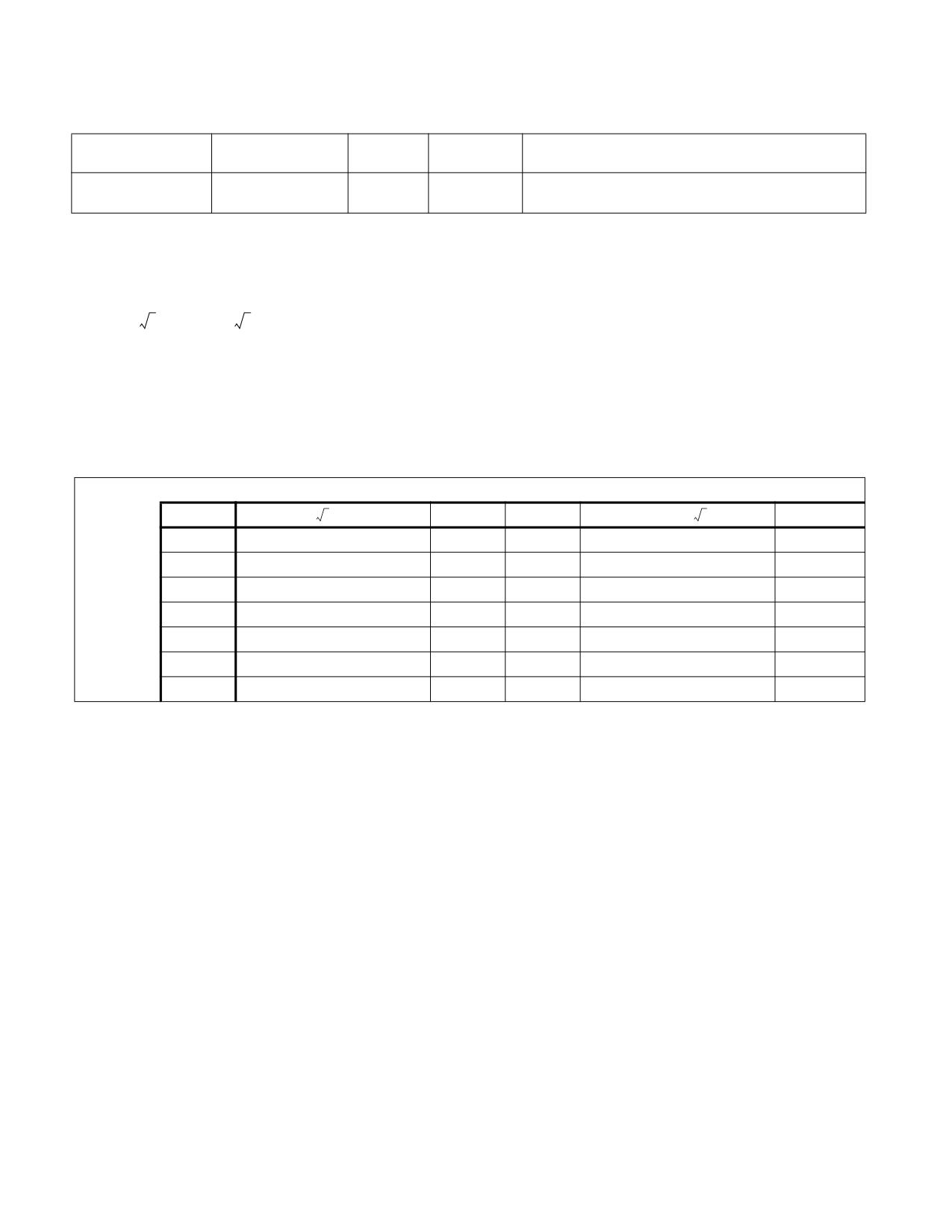
INSTRUCTION SET REFERENCE, A-L
FYL2XP1-Compute y ∗ log2(x +1)
Opcode
Instruction
64-Bit
Compat/
Description
Mode
Leg Mode
D9 F9
FYL2XP1
Valid
Valid
Replace ST(1) with ST(1) ∗ log2(ST(0) + 1.0) and pop the
register stack.
Description
Computes (ST(1) ∗ log2(ST(0) + 1.0)), stores the result in register ST(1), and pops the FPU register stack. The
source operand in ST(0) must be in the range:
-(1 -
2⁄2))to(1-
2⁄2)
The source operand in ST(1) can range from -∞ to +∞. If the ST(0) operand is outside of its acceptable range, the
result is undefined and software should not rely on an exception being generated. Under some circumstances
exceptions may be generated when ST(0) is out of range, but this behavior is implementation specific and not
guaranteed.
The following table shows the results obtained when taking the log epsilon of various classes of numbers, assuming
that underflow does not occur.
Table 3-49. FYL2XP1 Results
ST(0)
-(1 - (
2⁄2
)) to -0
-0
+0
+0 to +(1 - (
2⁄2
))
NaN
− ∞
+∞
*
*
- ∞
NaN
ST(1)
- F
+F
+0
-0
- F
NaN
− 0
+0
+0
-0
- 0
NaN
+0
- 0
- 0
+0
+0
NaN
+F
- F
- 0
+0
+F
NaN
+∞
- ∞
*
*
+∞
NaN
NaN
NaN
NaN
NaN
NaN
NaN
NOTES:
F Means finite floating-point value.
* Indicates floating-point invalid-operation (#IA) exception.
This instruction provides optimal accuracy for values of epsilon [the value in register ST(0)] that are close to 0. For
small epsilon (ε) values, more significant digits can be retained by using the FYL2XP1 instruction than by using
(ε+1) as an argument to the FYL2X instruction. The (ε+1) expression is commonly found in compound interest and
annuity calculations. The result can be simply converted into a value in another logarithm base by including a scale
factor in the ST(1) source operand. The following equation is used to calculate the scale factor for a particular loga-
rithm base, where n is the logarithm base desired for the result of the FYL2XP1 instruction:
scale factor := logn 2
This instruction’s operation is the same in non-64-bit modes and 64-bit mode.
Operation
ST(1) := ST(1) ∗ log2(ST(0) + 1.0);
PopRegisterStack;
FYL2XP1-Compute y * log2(x +1)
Vol. 2A
3-473
INSTRUCTION SET REFERENCE, A-L
FPU Flags Affected
C1
Set to 0 if stack underflow occurred.
Set if result was rounded up; cleared otherwise.
C0, C2, C3
Undefined.
Floating-Point Exceptions
#IS
Stack underflow occurred.
#IA
Either operand is an SNaN value or unsupported format.
#D
Source operand is a denormal value.
#U
Result is too small for destination format.
#O
Result is too large for destination format.
#P
Value cannot be represented exactly in destination format.
Protected Mode Exceptions
#NM
CR0.EM[bit 2] or CR0.TS[bit 3] = 1.
#MF
If there is a pending x87 FPU exception.
#UD
If the LOCK prefix is used.
Real-Address Mode Exceptions
Same exceptions as in protected mode.
Virtual-8086 Mode Exceptions
Same exceptions as in protected mode.
Compatibility Mode Exceptions
Same exceptions as in protected mode.
64-Bit Mode Exceptions
Same exceptions as in protected mode.
3-474
Vol. 2A
FYL2XP1-Compute y * log2(x +1)

INSTRUCTION SET REFERENCE, A-L
GF2P8AFFINEINVQB-Galois Field Affine Transformation Inverse
Opcode/
Op/
64/32 bit
CPUID Feature
Description
Instruction
En
Mode
Flag
Support
66 0F3A CF /r /ib
A
V/V
GFNI
Computes inverse affine transformation in the
GF2P8AFFINEINVQB xmm1,
finite field GF(2^8).
xmm2/m128, imm8
VEX.128.66.0F3A.W1 CF /r /ib
B
V/V
AVX
Computes inverse affine transformation in the
VGF2P8AFFINEINVQB xmm1, xmm2,
GFNI
finite field GF(2^8).
xmm3/m128, imm8
VEX.256.66.0F3A.W1 CF /r /ib
B
V/V
AVX
Computes inverse affine transformation in the
VGF2P8AFFINEINVQB ymm1, ymm2,
GFNI
finite field GF(2^8).
ymm3/m256, imm8
EVEX.128.66.0F3A.W1 CF /r /ib
C
V/V
AVX512VL
Computes inverse affine transformation in the
VGF2P8AFFINEINVQB xmm1{k1}{z},
GFNI
finite field GF(2^8).
xmm2, xmm3/m128/m64bcst, imm8
EVEX.256.66.0F3A.W1 CF /r /ib
C
V/V
AVX512VL
Computes inverse affine transformation in the
VGF2P8AFFINEINVQB ymm1{k1}{z},
GFNI
finite field GF(2^8).
ymm2, ymm3/m256/m64bcst, imm8
EVEX.512.66.0F3A.W1 CF /r /ib
C
V/V
AVX512F
Computes inverse affine transformation in the
VGF2P8AFFINEINVQB zmm1{k1}{z},
GFNI
finite field GF(2^8).
zmm2, zmm3/m512/m64bcst, imm8
Instruction Operand Encoding
Op/En
Tuple
Operand 1
Operand 2
Operand 3
Operand 4
A
N/A
ModRM:reg (r, w)
ModRM:r/m (r)
imm8 (r)
N/A
B
N/A
ModRM:reg (w)
VEX.vvvv (r)
ModRM:r/m (r)
imm8 (r)
C
Full
ModRM:reg (w)
EVEX.vvvv (r)
ModRM:r/m (r)
imm8 (r)
Description
The AFFINEINVB instruction computes an affine transformation in the Galois Field 28. For this instruction, an affine
transformation is defined by A * inv(x) + b where “A” is an 8 by 8 bit matrix, and “x” and “b” are 8-bit vectors. The
inverse of the bytes in x is defined with respect to the reduction polynomial x8 + x4 + x3 + x + 1.
One SIMD register (operand 1) holds “x” as either 16, 32 or 64 8-bit vectors. A second SIMD (operand 2) register
or memory operand contains 2, 4, or 8 “A” values, which are operated upon by the correspondingly aligned 8 “x”
values in the first register. The “b” vector is constant for all calculations and contained in the immediate byte.
The EVEX encoded form of this instruction does not support memory fault suppression. The SSE encoded forms of
the instruction require 16B alignment on their memory operations.
The inverse of each byte is given by the following table. The upper nibble is on the vertical axis and the lower nibble
is on the horizontal axis. For example, the inverse of 0x95 is 0x8A.
GF2P8AFFINEINVQB-Galois Field Affine Transformation Inverse
Vol. 2A
3-475

INSTRUCTION SET REFERENCE, A-L
Table 3-50. Inverse Byte Listings
-
0
1
2
3
4
5
6
7
8
9
A
B
C
D
E
F
0
0
1
8D
F6
CB
52
7B
D1
E8
4F
29
C0
B0
E1
E5
C7
1
74
B4
AA
4B
99
2B
60
5F
58
3F
FD
CC
FF
40
EE
B2
2
3A
6E
5A
F1
55
4D
A8
C9
C1
A
98
15
30
44
A2
C2
3
2C
45
92
6C
F3
39
66
42
F2
35
20
6F
77
BB
59
19
4
1D
FE
37
67
2D
31
F5
69
A7
64
AB
13
54
25
E9
9
5
ED
5C
5
CA
4C
24
87
BF
18
3E
22
F0
51
EC
61
17
6
16
5E
AF
D3
49
A6
36
43
F4
47
91
DF
33
93
21
3B
7
79
B7
97
85
10
B5
BA
3C
B6
70
D0
6
A1
FA
81
82
8
83
7E
7F
80
96
73
BE
56
9B
9E
95
D9
F7
2
B9
A4
9
DE
6A
32
6D
D8
8A
84
72
2A
14
9F
88
F9
DC
89
9A
A
FB
7C
2E
C3
8F
B8
65
48
26
C8
12
4A
CE
E7
D2
62
B
C
E0
1F
EF
11
75
78
71
A5
8E
76
3D
BD
BC
86
57
C
B
28
2F
A3
DA
D4
E4
F
A9
27
53
4
1B
FC
AC
E6
D
7A
7
AE
63
C5
DB
E2
EA
94
8B
C4
D5
9D
F8
90
6B
E
B1
D
D6
EB
C6
E
CF
AD
8
4E
D7
E3
5D
50
1E
B3
F
5B
23
38
34
68
46
3
8C
DD
9C
7D
A0
CD
1A
41
1C
Operation
define affine_inverse_byte(tsrc2qw, src1byte, imm):
FOR i := 0 to 7:
* parity(x) = 1 if x has an odd number of 1s in it, and 0 otherwise.*
* inverse(x) is defined in the table above *
retbyte.bit[i] := parity(tsrc2qw.byte[7-i] AND inverse(src1byte)) XOR imm8.bit[i]
return retbyte
VGF2P8AFFINEINVQB dest, src1, src2, imm8 (EVEX Encoded Version)
(KL, VL) = (2, 128), (4, 256), (8, 512)
FOR j := 0 TO KL-1:
IF SRC2 is memory and EVEX.b==1:
tsrc2 := SRC2.qword[0]
ELSE:
tsrc2 := SRC2.qword[j]
FOR b := 0 to 7:
IF k1[j*8+b] OR *no writemask*:
FOR i := 0 to 7:
DEST.qword[j].byte[b] := affine_inverse_byte(tsrc2, SRC1.qword[j].byte[b], imm8)
ELSE IF *zeroing*:
DEST.qword[j].byte[b] := 0
*ELSE DEST.qword[j].byte[b] remains unchanged*
DEST[MAX_VL-1:VL] := 0
3-476
Vol. 2A
GF2P8AFFINEINVQB-Galois Field Affine Transformation Inverse
INSTRUCTION SET REFERENCE, A-L
VGF2P8AFFINEINVQB dest, src1, src2, imm8 (128b and 256b VEX Encoded Versions)
(KL, VL) = (2, 128), (4, 256)
FOR j := 0 TO KL-1:
FOR b := 0 to 7:
DEST.qword[j].byte[b] := affine_inverse_byte(SRC2.qword[j], SRC1.qword[j].byte[b], imm8)
DEST[MAX_VL-1:VL] := 0
GF2P8AFFINEINVQB srcdest, src1, imm8 (128b SSE Encoded Version)
FOR j := 0 TO 1:
FOR b := 0 to 7:
SRCDEST.qword[j].byte[b] := affine_inverse_byte(SRC1.qword[j], SRCDEST.qword[j].byte[b], imm8)
Intel C/C++ Compiler Intrinsic Equivalent
(V)GF2P8AFFINEINVQB __m128i _mm_gf2p8affineinv_epi64_epi8(__m128i, __m128i, int);
(V)GF2P8AFFINEINVQB __m128i _mm_mask_gf2p8affineinv_epi64_epi8(__m128i, __mmask16, __m128i, __m128i, int);
(V)GF2P8AFFINEINVQB __m128i _mm_maskz_gf2p8affineinv_epi64_epi8(__mmask16, __m128i, __m128i, int);
VGF2P8AFFINEINVQB __m256i _mm256_gf2p8affineinv_epi64_epi8(__m256i, __m256i, int);
VGF2P8AFFINEINVQB __m256i _mm256_mask_gf2p8affineinv_epi64_epi8(__m256i, __mmask32, __m256i, __m256i, int);
VGF2P8AFFINEINVQB __m256i _mm256_maskz_gf2p8affineinv_epi64_epi8(__mmask32, __m256i, __m256i, int);
VGF2P8AFFINEINVQB __m512i _mm512_gf2p8affineinv_epi64_epi8(__m512i, __m512i, int);
VGF2P8AFFINEINVQB __m512i _mm512_mask_gf2p8affineinv_epi64_epi8(__m512i, __mmask64, __m512i, __m512i, int);
VGF2P8AFFINEINVQB __m512i _mm512_maskz_gf2p8affineinv_epi64_epi8(__mmask64, __m512i, __m512i, int);
SIMD Floating-Point Exceptions
None.
Other Exceptions
Legacy-encoded and VEX-encoded: See Table 2-21, “Type 4 Class Exception Conditions.”
EVEX-encoded: See Table 2-50, “Type E4NF Class Exception Conditions.”
GF2P8AFFINEINVQB-Galois Field Affine Transformation Inverse
Vol. 2A
3-477

INSTRUCTION SET REFERENCE, A-L
GF2P8AFFINEQB-Galois Field Affine Transformation
Opcode/
Op/
64/32 bit
CPUID Feature
Description
Instruction
En
Mode
Flag
Support
66 0F3A CE /r /ib
A
V/V
GFNI
Computes affine transformation in the finite
GF2P8AFFINEQB xmm1,
field GF(2^8).
xmm2/m128, imm8
VEX.128.66.0F3A.W1 CE /r /ib
B
V/V
AVX
Computes affine transformation in the finite
VGF2P8AFFINEQB xmm1, xmm2,
GFNI
field GF(2^8).
xmm3/m128, imm8
VEX.256.66.0F3A.W1 CE /r /ib
B
V/V
AVX
Computes affine transformation in the finite
VGF2P8AFFINEQB ymm1, ymm2,
GFNI
field GF(2^8).
ymm3/m256, imm8
EVEX.128.66.0F3A.W1 CE /r /ib
C
V/V
AVX512VL
Computes affine transformation in the finite
VGF2P8AFFINEQB xmm1{k1}{z},
GFNI
field GF(2^8).
xmm2, xmm3/m128/m64bcst, imm8
EVEX.256.66.0F3A.W1 CE /r /ib
C
V/V
AVX512VL
Computes affine transformation in the finite
VGF2P8AFFINEQB ymm1{k1}{z},
GFNI
field GF(2^8).
ymm2, ymm3/m256/m64bcst, imm8
EVEX.512.66.0F3A.W1 CE /r /ib
C
V/V
AVX512F
Computes affine transformation in the finite
VGF2P8AFFINEQB zmm1{k1}{z},
GFNI
field GF(2^8).
zmm2, zmm3/m512/m64bcst, imm8
Instruction Operand Encoding
Op/En
Tuple
Operand 1
Operand 2
Operand 3
Operand 4
A
N/A
ModRM:reg (r, w)
ModRM:r/m (r)
imm8 (r)
N/A
B
N/A
ModRM:reg (w)
VEX.vvvv (r)
ModRM:r/m (r)
imm8 (r)
C
Full
ModRM:reg (w)
EVEX.vvvv (r)
ModRM:r/m (r)
imm8 (r)
Description
The AFFINEB instruction computes an affine transformation in the Galois Field 28. For this instruction, an affine
transformation is defined by A * x + b where “A” is an 8 by 8 bit matrix, and “x” and “b” are 8-bit vectors. One SIMD
register (operand 1) holds “x” as either 16, 32 or 64 8-bit vectors. A second SIMD (operand 2) register or memory
operand contains 2, 4, or 8 “A” values, which are operated upon by the correspondingly aligned 8 “x” values in the
first register. The “b” vector is constant for all calculations and contained in the immediate byte.
The EVEX encoded form of this instruction does not support memory fault suppression. The SSE encoded forms of
the instruction require16B alignment on their memory operations.
Operation
define parity(x):
t := 0
// single bit
FOR i := 0 to 7:
t = t xor x.bit[i]
return t
define affine_byte(tsrc2qw, src1byte, imm):
FOR i := 0 to 7:
* parity(x) = 1 if x has an odd number of 1s in it, and 0 otherwise.*
retbyte.bit[i] := parity(tsrc2qw.byte[7-i] AND src1byte) XOR imm8.bit[i]
return retbyte
3-478
Vol. 2A
GF2P8AFFINEQB-Galois Field Affine Transformation
INSTRUCTION SET REFERENCE, A-L
VGF2P8AFFINEQB dest, src1, src2, imm8 (EVEX Encoded Version)
(KL, VL) = (2, 128), (4, 256), (8, 512)
FOR j := 0 TO KL-1:
IF SRC2 is memory and EVEX.b==1:
tsrc2 := SRC2.qword[0]
ELSE:
tsrc2 := SRC2.qword[j]
FOR b := 0 to 7:
IF k1[j*8+b] OR *no writemask*:
DEST.qword[j].byte[b] := affine_byte(tsrc2, SRC1.qword[j].byte[b], imm8)
ELSE IF *zeroing*:
DEST.qword[j].byte[b] := 0
*ELSE DEST.qword[j].byte[b] remains unchanged*
DEST[MAX_VL-1:VL] := 0
VGF2P8AFFINEQB dest, src1, src2, imm8 (128b and 256b VEX Encoded Versions)
(KL, VL) = (2, 128), (4, 256)
FOR j := 0 TO KL-1:
FOR b := 0 to 7:
DEST.qword[j].byte[b] := affine_byte(SRC2.qword[j], SRC1.qword[j].byte[b], imm8)
DEST[MAX_VL-1:VL] := 0
GF2P8AFFINEQB srcdest, src1, imm8 (128b SSE Encoded Version)
FOR j := 0 TO 1:
FOR b := 0 to 7:
SRCDEST.qword[j].byte[b] := affine_byte(SRC1.qword[j], SRCDEST.qword[j].byte[b], imm8)
Intel C/C++ Compiler Intrinsic Equivalent
(V)GF2P8AFFINEQB __m128i _mm_gf2p8affine_epi64_epi8(__m128i, __m128i, int);
(V)GF2P8AFFINEQB __m128i _mm_mask_gf2p8affine_epi64_epi8(__m128i, __mmask16, __m128i, __m128i, int);
(V)GF2P8AFFINEQB __m128i _mm_maskz_gf2p8affine_epi64_epi8(__mmask16, __m128i, __m128i, int);
VGF2P8AFFINEQB __m256i _mm256_gf2p8affine_epi64_epi8(__m256i, __m256i, int);
VGF2P8AFFINEQB __m256i _mm256_mask_gf2p8affine_epi64_epi8(__m256i, __mmask32, __m256i, __m256i, int);
VGF2P8AFFINEQB __m256i _mm256_maskz_gf2p8affine_epi64_epi8(__mmask32, __m256i, __m256i, int);
VGF2P8AFFINEQB __m512i _mm512_gf2p8affine_epi64_epi8(__m512i, __m512i, int);
VGF2P8AFFINEQB __m512i _mm512_mask_gf2p8affine_epi64_epi8(__m512i, __mmask64, __m512i, __m512i, int);
VGF2P8AFFINEQB __m512i _mm512_maskz_gf2p8affine_epi64_epi8(__mmask64, __m512i, __m512i, int);
SIMD Floating-Point Exceptions
None.
Other Exceptions
Legacy-encoded and VEX-encoded: See Table 2-21, “Type 4 Class Exception Conditions.”
EVEX-encoded: See Table 2-50, “Type E4NF Class Exception Conditions.”
GF2P8AFFINEQB-Galois Field Affine Transformation
Vol. 2A
3-479

INSTRUCTION SET REFERENCE, A-L
GF2P8MULB-Galois Field Multiply Bytes
Opcode/
Op/
64/32 bit
CPUID Feature
Description
Instruction
En
Mode
Flag
Support
66 0F38 CF /r
A
V/V
GFNI
Multiplies elements in the finite field GF(2^8).
GF2P8MULB xmm1, xmm2/m128
VEX.128.66.0F38.W0 CF /r
B
V/V
AVX
Multiplies elements in the finite field GF(2^8).
VGF2P8MULB xmm1, xmm2,
GFNI
xmm3/m128
VEX.256.66.0F38.W0 CF /r
B
V/V
AVX
Multiplies elements in the finite field GF(2^8).
VGF2P8MULB ymm1, ymm2,
GFNI
ymm3/m256
EVEX.128.66.0F38.W0 CF /r
C
V/V
AVX512VL
Multiplies elements in the finite field GF(2^8).
VGF2P8MULB xmm1{k1}{z}, xmm2,
GFNI
xmm3/m128
EVEX.256.66.0F38.W0 CF /r
C
V/V
AVX512VL
Multiplies elements in the finite field GF(2^8).
VGF2P8MULB ymm1{k1}{z}, ymm2,
GFNI
ymm3/m256
EVEX.512.66.0F38.W0 CF /r
C
V/V
AVX512F
Multiplies elements in the finite field GF(2^8).
VGF2P8MULB zmm1{k1}{z}, zmm2,
GFNI
zmm3/m512
Instruction Operand Encoding
Op/En
Tuple
Operand 1
Operand 2
Operand 3
Operand 4
A
N/A
ModRM:reg (r, w)
ModRM:r/m (r)
N/A
N/A
B
N/A
ModRM:reg (w)
VEX.vvvv (r)
ModRM:r/m (r)
N/A
C
Full Mem
ModRM:reg (w)
EVEX.vvvv (r)
ModRM:r/m (r)
N/A
Description
The instruction multiplies elements in the finite field GF(28), operating on a byte (field element) in the first source
operand and the corresponding byte in a second source operand. The field GF(28) is represented in polynomial
representation with the reduction polynomial x8 + x4 + x3 + x + 1.
This instruction does not support broadcasting.
The EVEX encoded form of this instruction supports memory fault suppression. The SSE encoded forms of the
instruction require16B alignment on their memory operations.
Operation
define gf2p8mul_byte(src1byte, src2byte):
tword := 0
FOR i := 0 to 7:
IF src2byte.bit[i]:
tword := tword XOR (src1byte<< i)
* carry out polynomial reduction by the characteristic polynomial p*
FOR i := 14 downto 8:
p := 0x11B << (i-8)
*0x11B = 0000_0001_0001_1011 in binary*
IF tword.bit[i]:
tword := tword XOR p
return tword.byte[0]
3-480
Vol. 2A
GF2P8MULB-Galois Field Multiply Bytes
INSTRUCTION SET REFERENCE, A-L
VGF2P8MULB dest, src1, src2 (EVEX Encoded Version)
(KL, VL) = (16, 128), (32, 256), (64, 512)
FOR j := 0 TO KL-1:
IF k1[j] OR *no writemask*:
DEST.byte[j] := gf2p8mul_byte(SRC1.byte[j], SRC2.byte[j])
ELSE iF *zeroing*:
DEST.byte[j] := 0
* ELSE DEST.byte[j] remains unchanged*
DEST[MAX_VL-1:VL] := 0
VGF2P8MULB dest, src1, src2 (128b and 256b VEX Encoded Versions)
(KL, VL) = (16, 128), (32, 256)
FOR j := 0 TO KL-1:
DEST.byte[j] := gf2p8mul_byte(SRC1.byte[j], SRC2.byte[j])
DEST[MAX_VL-1:VL] := 0
GF2P8MULB srcdest, src1 (128b SSE Encoded Version)
FOR j := 0 TO 15:
SRCDEST.byte[j] :=gf2p8mul_byte(SRCDEST.byte[j], SRC1.byte[j])
Intel C/C++ Compiler Intrinsic Equivalent
(V)GF2P8MULB __m128i _mm_gf2p8mul_epi8(__m128i, __m128i);
(V)GF2P8MULB __m128i _mm_mask_gf2p8mul_epi8(__m128i, __mmask16, __m128i, __m128i);
(V)GF2P8MULB __m128i _mm_maskz_gf2p8mul_epi8(__mmask16, __m128i, __m128i);
VGF2P8MULB __m256i _mm256_gf2p8mul_epi8(__m256i, __m256i);
VGF2P8MULB __m256i _mm256_mask_gf2p8mul_epi8(__m256i, __mmask32, __m256i, __m256i);
VGF2P8MULB __m256i _mm256_maskz_gf2p8mul_epi8(__mmask32, __m256i, __m256i);
VGF2P8MULB __m512i _mm512_gf2p8mul_epi8(__m512i, __m512i);
VGF2P8MULB __m512i _mm512_mask_gf2p8mul_epi8(__m512i, __mmask64, __m512i, __m512i);
VGF2P8MULB __m512i _mm512_maskz_gf2p8mul_epi8(__mmask64, __m512i, __m512i);
SIMD Floating-Point Exceptions
None.
Other Exceptions
Legacy-encoded and VEX-encoded: See Table 2-21, “Type 4 Class Exception Conditions.”
EVEX-encoded: See Table 2-49, “Type E4 Class Exception Conditions.”
GF2P8MULB-Galois Field Multiply Bytes
Vol. 2A
3-481
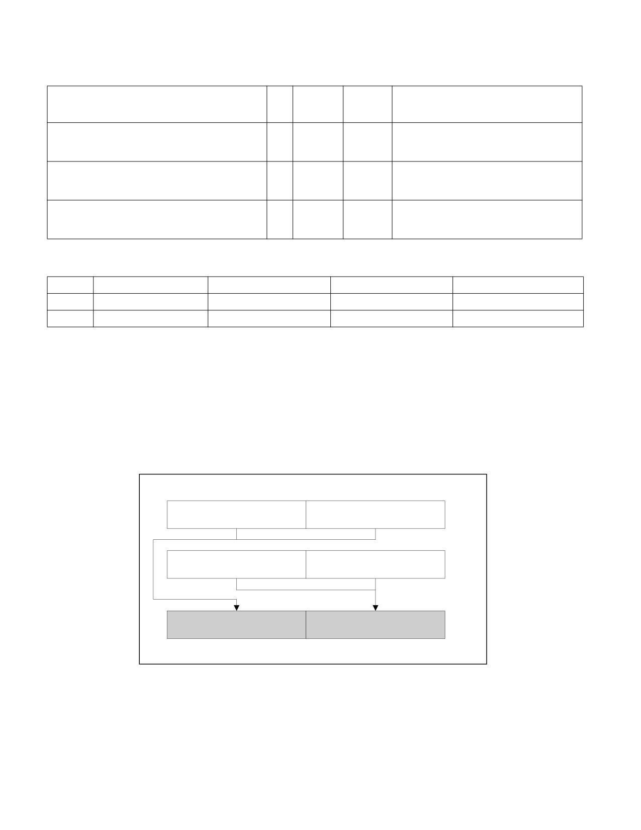
INSTRUCTION SET REFERENCE, A-L
HADDPD-Packed Double Precision Floating-Point Horizontal Add
Opcode/
Op/
64/32-bit
CPUID
Description
Instruction
En
Mode
Feature
Flag
66 0F 7C /r
RM
V/V
SSE3
Horizontal add packed double precision
floating-point values from xmm2/m128 to
HADDPD xmm1, xmm2/m128
xmm1.
VEX.128.66.0F.WIG 7C /r
RVM
V/V
AVX
Horizontal add packed double precision
floating-point values from xmm2 and
VHADDPD xmm1,xmm2, xmm3/m128
xmm3/mem.
VEX.256.66.0F.WIG 7C /r
RVM
V/V
AVX
Horizontal add packed double precision
floating-point values from ymm2 and
VHADDPD ymm1, ymm2, ymm3/m256
ymm3/mem.
Instruction Operand Encoding
Op/En
Operand 1
Operand 2
Operand 3
Operand 4
RM
ModRM:reg (r, w)
ModRM:r/m (r)
N/A
N/A
RVM
ModRM:reg (w)
VEX.vvvv (r)
ModRM:r/m (r)
N/A
Description
Adds the double precision floating-point values in the high and low quadwords of the destination operand and
stores the result in the low quadword of the destination operand.
Adds the double precision floating-point values in the high and low quadwords of the source operand and stores the
result in the high quadword of the destination operand.
In 64-bit mode, use of the REX.R prefix permits this instruction to access additional registers (XMM8-XMM15).
See Figure 3-17 for HADDPD; see Figure 3-18 for VHADDPD.
HADDPD xmm1, xmm2/m128
xmm2
[127:64]
[63:0]
/m128
[127:64]
[63:0]
xmm1
xmm2/m128[63:0] +
Result:
xmm1[63:0] + xmm1[127:64]
xmm2/m128[127:64]
xmm1
[127:64]
[63:0]
OM15993
Figure 3-17. HADDPD-Packed Double Precision Floating-Point Horizontal Add
3-482
Vol. 2A
HADDPD-Packed Double Precision Floating-Point Horizontal Add
INSTRUCTION SET REFERENCE, A-L
SRC1
X3
X2
X1
X0
SRC2
Y3
Y
2
Y1
Y0
DEST
Y2 + Y3
X2 + X3
Y0 + Y1
X0 + X1
Figure 3-18. VHADDPD Operation
128-bit Legacy SSE version: The second source can be an XMM register or an 128-bit memory location. The desti-
nation is not distinct from the first source XMM register and the upper bits (MAXVL-1:128) of the corresponding
YMM register destination are unmodified.
VEX.128 encoded version: the first source operand is an XMM register or 128-bit memory location. The destination
operand is an XMM register. The upper bits (MAXVL-1:128) of the corresponding YMM register destination are
zeroed.
VEX.256 encoded version: The first source operand is a YMM register. The second source operand can be a YMM
register or a 256-bit memory location. The destination operand is a YMM register.
Operation
HADDPD (128-bit Legacy SSE Version)
DEST[63:0] := SRC1[127:64] + SRC1[63:0]
DEST[127:64] := SRC2[127:64] + SRC2[63:0]
DEST[MAXVL-1:128] (Unmodified)
VHADDPD (VEX.128 Encoded Version)
DEST[63:0] := SRC1[127:64] + SRC1[63:0]
DEST[127:64] := SRC2[127:64] + SRC2[63:0]
DEST[MAXVL-1:128] := 0
VHADDPD (VEX.256 Encoded Version)
DEST[63:0] := SRC1[127:64] + SRC1[63:0]
DEST[127:64] := SRC2[127:64] + SRC2[63:0]
DEST[191:128] := SRC1[255:192] + SRC1[191:128]
DEST[255:192] := SRC2[255:192] + SRC2[191:128]
Intel C/C++ Compiler Intrinsic Equivalent
VHADDPD __m256d _mm256_hadd_pd (__m256d a, __m256d b);
HADDPD __m128d _mm_hadd_pd (__m128d a, __m128d b);
Exceptions
When the source operand is a memory operand, the operand must be aligned on a 16-byte boundary or a general-
protection exception (#GP) will be generated.
Numeric Exceptions
Overflow, Underflow, Invalid, Precision, Denormal.
HADDPD-Packed Double Precision Floating-Point Horizontal Add
Vol. 2A
3-483
INSTRUCTION SET REFERENCE, A-L
Other Exceptions
See Table 2-19, “Type 2 Class Exception Conditions.”
3-484
Vol. 2A
HADDPD-Packed Double Precision Floating-Point Horizontal Add
INSTRUCTION SET REFERENCE, A-L
HADDPS-Packed Single Precision Floating-Point Horizontal Add
Opcode/
Op/
64/32-bit
CPUID
Description
Instruction
En
Mode
Feature
Flag
F2 0F 7C /r
RM
V/V
SSE3
Horizontal add packed single precision
floating-point values from xmm2/m128 to
HADDPS xmm1, xmm2/m128
xmm1.
VEX.128.F2.0F.WIG 7C /r
RVM
V/V
AVX
Horizontal add packed single precision floating-
point values from xmm2 and xmm3/mem.
VHADDPS xmm1, xmm2, xmm3/m128
VEX.256.F2.0F.WIG 7C /r
RVM
V/V
AVX
Horizontal add packed single precision floating-
point values from ymm2 and ymm3/mem.
VHADDPS ymm1, ymm2, ymm3/m256
Instruction Operand Encoding
Op/En
Operand 1
Operand 2
Operand 3
Operand 4
RM
ModRM:reg (r, w)
ModRM:r/m (r)
N/A
N/A
RVM
ModRM:reg (w)
VEX.vvvv (r)
ModRM:r/m (r)
N/A
Description
Adds the single precision floating-point values in the first and second dwords of the destination operand and stores
the result in the first dword of the destination operand.
Adds single precision floating-point values in the third and fourth dword of the destination operand and stores the
result in the second dword of the destination operand.
Adds single precision floating-point values in the first and second dword of the source operand and stores the result
in the third dword of the destination operand.
Adds single precision floating-point values in the third and fourth dword of the source operand and stores the result
in the fourth dword of the destination operand.
In 64-bit mode, use of the REX.R prefix permits this instruction to access additional registers (XMM8-XMM15).
HADDPS-Packed Single Precision Floating-Point Horizontal Add
Vol. 2A
3-485
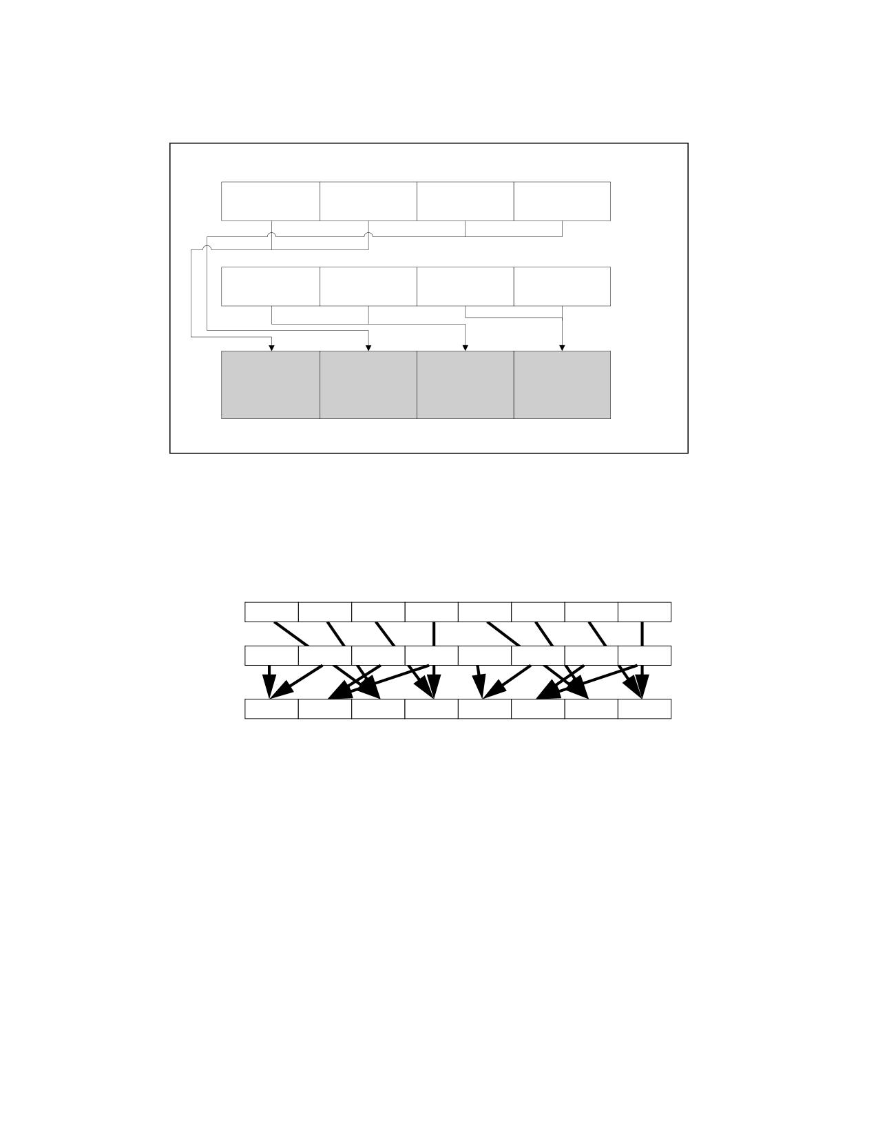
INSTRUCTION SET REFERENCE, A-L
See Figure 3-19 for HADDPS; see Figure 3-20 for VHADDPS.
HADDPS xmm1, xmm2/m128
xmm2/
[127:96]
[95:64]
[63:32]
[31:0]
m128
[127:96]
[95:64]
[63:32]
[31:0]
xmm1
xmm2/m128
xmm2/m128
xmm1[95:64] +
xmm1[31:0] +
RESULT:
[95:64] + xmm2/
[31:0] + xmm2/
xmm1[127:96]
xmm1[63:32]
xmm1
m128[127:96]
m128[63:32]
[127:96]
[95:64]
[63:32]
[31:0]
OM15994
Figure 3-19. HADDPS-Packed Single Precision Floating-Point Horizontal Add
SRC1
X7
X6
X5
X4
X3
X2
X1
X0
SRC2
Y7
Y6
Y5
Y4
Y3
Y2
Y1
Y0
DEST
Y6+Y7
Y4+Y5
X6+X7
X4+X5
Y2+Y3
Y0+Y1
X2+X3
X0+X1
Figure 3-20. VHADDPS Operation
128-bit Legacy SSE version: The second source can be an XMM register or an 128-bit memory location. The desti-
nation is not distinct from the first source XMM register and the upper bits (MAXVL-1:128) of the corresponding
YMM register destination are unmodified.
VEX.128 encoded version: the first source operand is an XMM register or 128-bit memory location. The destination
operand is an XMM register. The upper bits (MAXVL-1:128) of the corresponding YMM register destination are
zeroed.
VEX.256 encoded version: The first source operand is a YMM register. The second source operand can be a YMM
register or a 256-bit memory location. The destination operand is a YMM register.
3-486
Vol. 2A
HADDPS-Packed Single Precision Floating-Point Horizontal Add
INSTRUCTION SET REFERENCE, A-L
Operation
HADDPS (128-bit Legacy SSE Version)
DEST[31:0] := SRC1[63:32] + SRC1[31:0]
DEST[63:32] := SRC1[127:96] + SRC1[95:64]
DEST[95:64] := SRC2[63:32] + SRC2[31:0]
DEST[127:96] := SRC2[127:96] + SRC2[95:64]
DEST[MAXVL-1:128] (Unmodified)
VHADDPS (VEX.128 Encoded Version)
DEST[31:0] := SRC1[63:32] + SRC1[31:0]
DEST[63:32] := SRC1[127:96] + SRC1[95:64]
DEST[95:64] := SRC2[63:32] + SRC2[31:0]
DEST[127:96] := SRC2[127:96] + SRC2[95:64]
DEST[MAXVL-1:128] := 0
VHADDPS (VEX.256 Encoded Version)
DEST[31:0] := SRC1[63:32] + SRC1[31:0]
DEST[63:32] := SRC1[127:96] + SRC1[95:64]
DEST[95:64] := SRC2[63:32] + SRC2[31:0]
DEST[127:96] := SRC2[127:96] + SRC2[95:64]
DEST[159:128] := SRC1[191:160] + SRC1[159:128]
DEST[191:160] := SRC1[255:224] + SRC1[223:192]
DEST[223:192] := SRC2[191:160] + SRC2[159:128]
DEST[255:224] := SRC2[255:224] + SRC2[223:192]
Intel C/C++ Compiler Intrinsic Equivalent
HADDPS __m128 _mm_hadd_ps (__m128 a, __m128 b);
VHADDPS __m256 _mm256_hadd_ps (__m256 a, __m256 b);
Exceptions
When the source operand is a memory operand, the operand must be aligned on a 16-byte boundary or a general-
protection exception (#GP) will be generated.
Numeric Exceptions
Overflow, Underflow, Invalid, Precision, Denormal.
Other Exceptions
See Table 2-19, “Type 2 Class Exception Conditions.”
HADDPS-Packed Single Precision Floating-Point Horizontal Add
Vol. 2A
3-487
INSTRUCTION SET REFERENCE, A-L
HLT-Halt
Opcode
Instruction
Op/
64-Bit
Compat/
Description
En
Mode
Leg Mode
F4
HLT
ZO
Valid
Valid
Halt
Instruction Operand Encoding
Op/En
Operand 1
Operand 2
Operand 3
Operand 4
ZO
N/A
N/A
N/A
N/A
Description
Stops instruction execution and places the processor in a HALT state. An enabled interrupt (including NMI and
SMI), a debug exception, the BINIT# signal, the INIT# signal, or the RESET# signal will resume execution. If an
interrupt (including NMI) is used to resume execution after a HLT instruction, the saved instruction pointer
(CS:EIP) points to the instruction following the HLT instruction.
When a HLT instruction is executed on an Intel 64 or IA-32 processor supporting Intel Hyper-Threading Technology,
only the logical processor that executes the instruction is halted. The other logical processors in the physical
processor remain active, unless they are each individually halted by executing a HLT instruction.
The HLT instruction is a privileged instruction. When the processor is running in protected or virtual-8086 mode,
the privilege level of a program or procedure must be 0 to execute the HLT instruction.
This instruction’s operation is the same in non-64-bit modes and 64-bit mode.
Operation
Enter Halt state;
Flags Affected
None.
Protected Mode Exceptions
#GP(0)
If the current privilege level is not 0.
#UD
If the LOCK prefix is used.
Real-Address Mode Exceptions
None.
Virtual-8086 Mode Exceptions
Same exceptions as in protected mode.
Compatibility Mode Exceptions
Same exceptions as in protected mode.
64-Bit Mode Exceptions
Same exceptions as in protected mode.
3-488
Vol. 2A
HLT-Halt
INSTRUCTION SET REFERENCE, A-L
HRESET-History Reset
Opcode/
Op/
64/32 bit
CPUID Feature
Description
Instruction
En
Mode
Flag
Support
F3 0F 3A F0 C0 /ib
A
V/V
HRESET
Processor history reset request. Controlled by the
HRESET imm8, <EAX>
EAX implicit operand.
Instruction Operand Encoding
Op/En
Tuple
Operand 1
Operand 2
Operand 3
Operand 4
A
N/A
ModRM:r/m (r)
N/A
N/A
N/A
Description
Requests the processor to selectively reset selected components of hardware history maintained by the current
logical processor. HRESET operation is controlled by the implicit EAX operand. The value of the explicit imm8
operand is ignored. This instruction can only be executed at privilege level 0.
The HRESET instruction can be used to request reset of multiple components of hardware history. Prior to the
execution of HRESET, the system software must take the following steps:
1. Enumerate the HRESET capabilities via CPUID.20H.0H:EBX, which indicates what components of hardware
history can be reset.
2. Only the bits enumerated by CPUID.20H.0H:EBX can be set in the IA32_HRESET_ENABLE MSR.
HRESET causes a general-protection exception (#GP) if EAX sets any bits that are not set in the IA32_HRESET_EN-
ABLE MSR.
Any attempt to execute the HRESET instruction inside a transactional region will result in a transaction abort.
Operation
IF EAX = 0
THEN NOP
ELSE
FOREACH i such that EAX[i] = 1
Reset prediction history for feature i
FI
Flags Affected
None.
Protected Mode Exceptions
#GP(0)
If CPL > 0 or (EAX AND NOT IA32_HRESET_ENABLE) ≠0.
#UD
If CPUID.07H.01H:EAX.HRESET[bit 22] = 0.
Real-Address Mode Exceptions
Same exceptions as in protected mode.
Virtual-8086 Mode Exceptions
#GP(0)
HRESET instruction is not recognized in virtual-8086 mode.
Compatibility Mode Exceptions
Same exceptions as in protected mode.
HRESET-History Reset
Vol. 2A
3-489
INSTRUCTION SET REFERENCE, A-L
64-Bit Mode Exceptions
Same exceptions as in protected mode.
3-490
Vol. 2A
HRESET-History Reset