FANUC a Series AC SERVO MOTOR. Description Manual (GFZ-65142E/02) - page 6
IV. FANUC AC SERVO MOTOR αC series
B-65142E/02
FANUC AC SERVO MOTOR αC series
1. GENERAL
GENERAL
1
The FANUC AC servo motor αC series is suitable for application to the
feed axes of machine tools. These motors have the following features:
High cost-effectiveness
High cost-effectiveness has been achieved. Although a low-power
amplifier is used, high acceleration is offered.
Compact
The use of the latest ferrite magnet, combined with an optimized
mechanical design, reduces both the overall length and weight. The result
is compact, lightweight servo motors.
Excellent waterproofing
The use of waterproof connectors and FANUC’s unique stator seal
provide excellent waterproofing, ensuring that no liquid, such as coolant,
can enter the motor.
Smooth rotation
Further improvements have been made to the unique magnetic pole shape
to minimize torque ripple. The result is extremely smooth rotation.
Controllability
The use of the latest servo software maintains controllability even when
a disturbance occurs.
High-performance
High-resolution pulse coder αA64 or αI64 is used in the standard
detector
configuration, enabling precise positioning.
Powerful brake
A powerful brake with an increased holding torque is available as an
option. The brake uses an asbestos-free design.
The αC series includes models αC3 and αC6, both of which are
compatible with α series models α3 and α6 in their installation size, and
models αC12 and αC22, which are compatible with series models α12
and α22 in their installation size.
153
2.TYPES OF MOTORS
AND DESIGNATION
FANUC AC SERVO MOTOR αC series
B-65142E/02
TYPES, OF, MOTORS, AND, DESIGNATION
2
The types and specifications of αC series servo motors are described as
follows.
Models
A06B-01jj-Bl ff
αC3/2000, andαC6/2000
jj
21 : Model αC3/2000
26 : Model αC6/2000
l
0 : Taper shaft (standard)
1 : Taper shaft with the brake (8Nm)
5 : Straight shaft
6 : Straight shaft with the brake (8Nm)
ff
75 : With the pulse coder αA64
77 : With the pulse coder αI64
The standard shafts used for models αC3/2000 and αC6/2000 are taper
shafts. Use a taper shaft as far as circumstances, such as the delivery
time and maintenance, permit.
Models
A06B-01jj-Bl ff
αC12/2000 and αC22/1500
jj
41 : Model αC12/2000
45 : Model αC22/1500
l
0 : Straight shaft (standard)
1 : Straight shaft with the brake (35Nm)
5 : Taper shaft
6 : Taper shaft with the brake (35Nm)
ff
75 : With the pulse coder αA64
77 : With the pulse coder αI64
A straight shaft is fitted as the standard shaft for models αC12/2000 and
αC22/1500. When early delivery and case-of-maintenance are
important, a straight shaft should be used.
Note
For the αC series, serial pulse coder A cannot be used.
154
3. SPECIFICATIONS AND
B-65142E/02
FANUC AC SERVO MOTOR αC series
CHARACTERISTICS
SPECIFICATIONS AND CHARACTERISTICS
3
155
3.SPECIFICATIONS AND
CHARACTERISTICS
FANUC AC SERVO MOTOR αC series
B-65142E/02
3.1
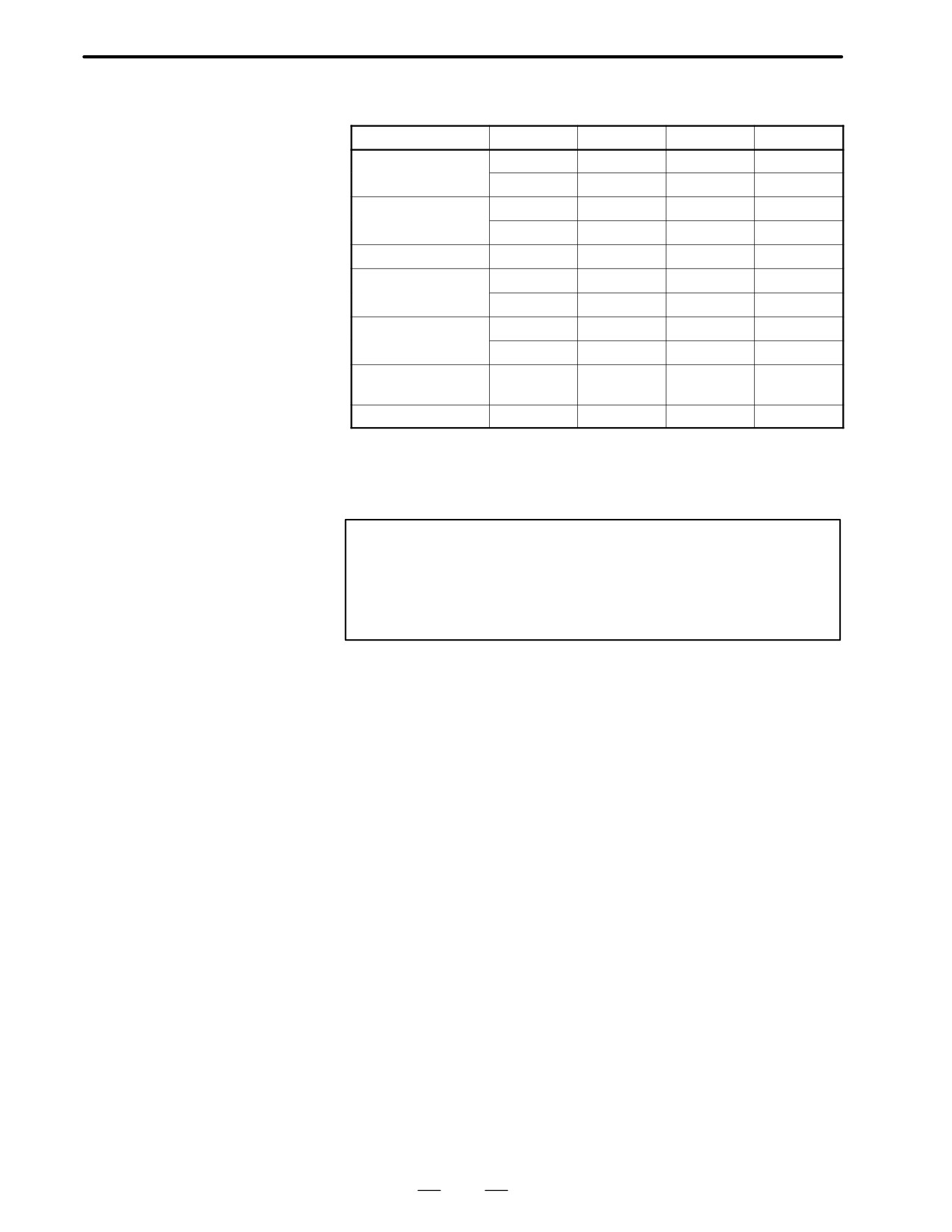
TYPES OF MOTORS
Item
Unit
αC3/2000
αC6/2000
αC12/2000
αC22/1500
AND
kw
0.3
0.6
1.0
1.5
SPECIFICATIONS
Output
HP
0.4
0.8
1.4
2.1
Nm
3.0
6.0
12
22
Rated torque
at stall
kgf⋅cm
31
61
122
224
Rating output
1/min
2000
2000
2000
1500
speed
Maximum
Nm
27
56
66
130
theoretical
torque
kgf⋅cm
280
570
670
1400
kg⋅m2
0.0014
0.0026
0.0062
0.012
Rotor inertia
kgf⋅cm⋅s2
0.014
0.027
0.064
0.12
Maximum
theoretical
rad/s2
20000
21000
11000
11000
acceleration
Weight
kg
8
13
18
29
The above values are under the condition at 20°C.
Note
The above values shown in the maximum theoretical torque
are the theoretical values.
The actual maximum torque is restricted by the current limit
values of the drive amplifier.
156
3. SPECIFICATIONS AND
B-65142E/02
FANUC AC SERVO MOTOR αC series
CHARACTERISTICS
3.2
CHARACTERISTIC
CURVE AND DATA
SHEET
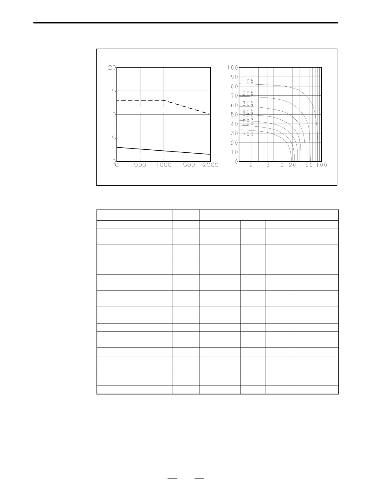
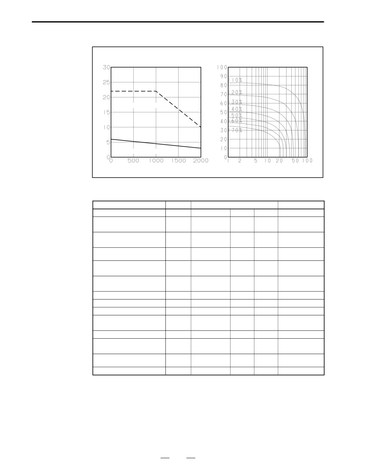
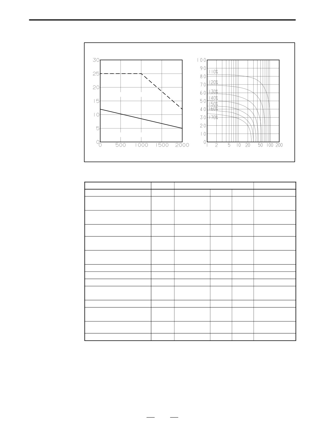
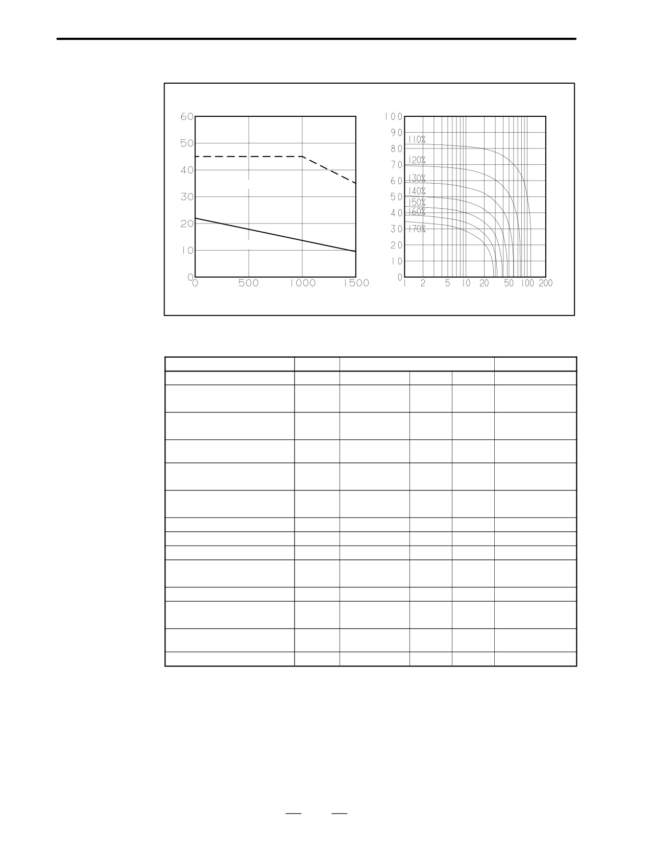
Speed-torque
The intermittent operation zone is determined by the input voltage
characteristics
applied to the drive amplifier. The curve shown is the value for the rated
input voltage (200V).
Overload duty
The overload duty characteristic curves are determined based on the
characteristic
temperature restriction for the single motor unit (the temperature is
restricted by means of a thermal trip built into the motor). The curves are
determined by assuming that the temperature increases gradually under
certain overload conditions. Therefore, the curves do not apply to the
rapid temperature rise which occurs, for example, when the motor shaft
is locked. (An overcurrent flows in the motor windings until the thermal
trip operates. The temperature rises momentarily.)
To detect such an abrupt temperature rise, the FANUC digital servo
system provides a software thermal function that uses servo software to
observe the current. During operation that is characterized by frequent
acceleration/deceleration cycles, control is imposed by the software
thermal function.
Driving units (such as amplifiers) and built-in detectors contain their own
overheating protection devices. Therefore, note that control may be
imposed according to how the equipment is being used.
Data sheet
The parameters given in the data sheet are representative values for an
ambient temperature of 20°C. They are subject to an error of +10%.
The indicated logical values are threshold values for the single motor unit
(when the motor is not restricted by the control system).
The maximum torque that can be produced during acceleration or
deceleration in actual use is calculated as the approximate product of the
motor torque constant and the current limit value of the amplifier.
Example : αC3/2000
A Motor torque constant = 1.06 (Nm/Arms)
A Amplifier limit value = 20 Apeak
A Maximum torque value
= 20 x 0.707 x 1.06
(Converted to an effective value)
= 14.9 Nm (Converted to an effective value)
This value is for reference only. The actual value will vary depending on
changes in the power supply, as well as variations in motor parameters and
amplifier limit values.
In some models, if the maximum current flows in the motor, the actual
maximum torque is affected by, for example, magnetic saturation. As a
result, the actual maximum torque will be lower than the calculated value.
The intermittent operation area (maximum torque value) indicated in the
speed to torque characteristics is the effective value, determined
according to the combination with the amplifier.
157
3.SPECIFICATIONS AND
CHARACTERISTICS
FANUC AC SERVO MOTOR αC series
B-65142E/02
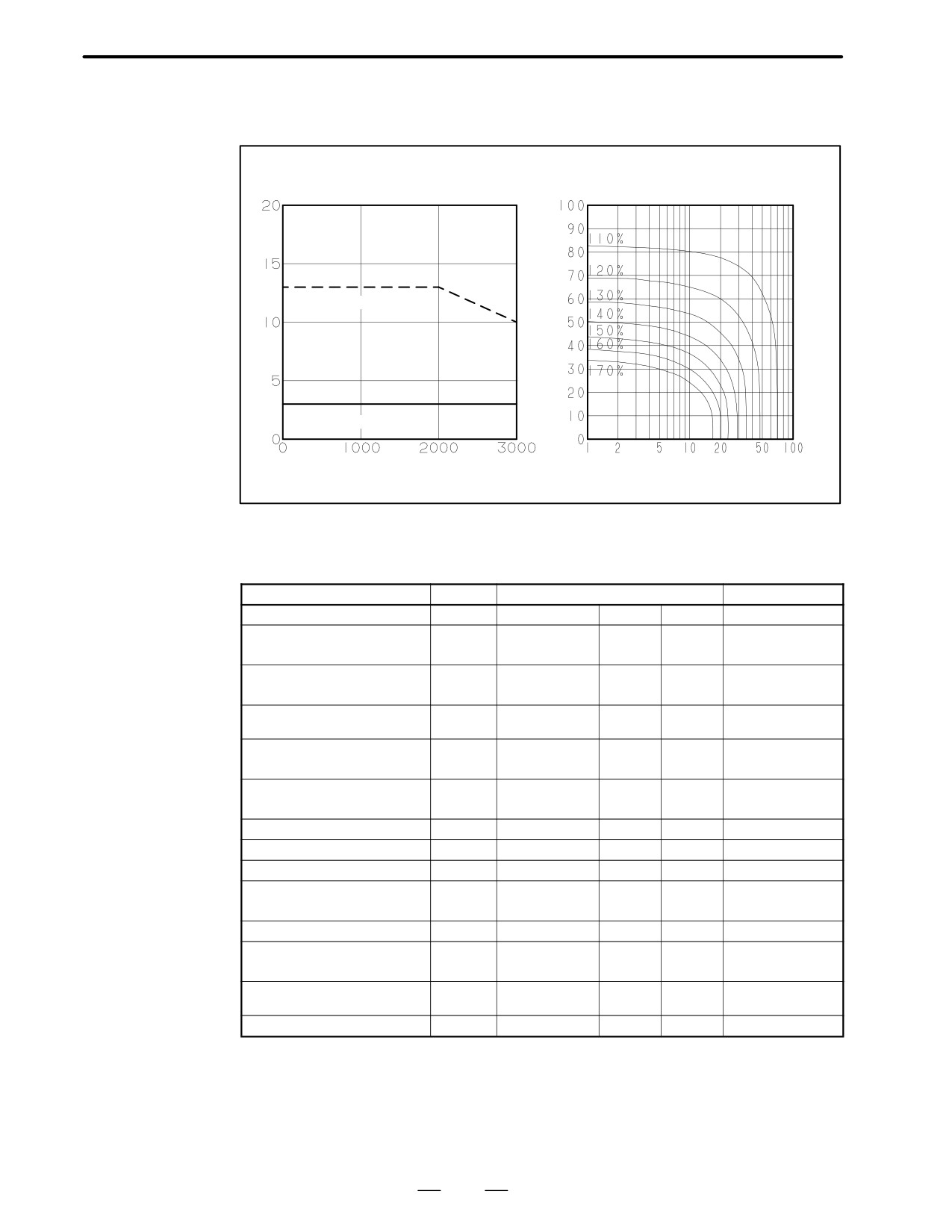
Model αC3/2000
Specification : A06B-0121-Bjjj
Torque
Duty
Speed - torque characteristics
Over load duty
(Nm)
(time %)
Intermittent operating
Continuous operating
Speed (1/min)
”ON” time (min.)
Data sheet
Parameter
Symbol
Value
Unit
Rating output speed
Nmax
2000
min -1
3. 0
Nm
Rated torque at stall
(*)
Ts
31
kgfcm
0. 0014
kgm2
Rotor inertia
Jm
0. 014
kgfcms2
Continuous RMS current at stall
Is
2. 8
A (rms)
(*)
1. 06
Nm/A (rms)
Torque constant
(*)
Kt
10. 8
kgfcm/A (rms)
Back EMF constant
(*)
Ke
37
V/1000min -1
(*)
Kv
0. 35
Vsec/rad
Armature resistance
(*)
Ra
1. 85
Ω
Mechanical time constant
(*)
tm
0. 006
s
Thermal time constant
tt
45
min
0. 3
Nm
Static friction
Tf
3
kgfcm
Maximum allowable current
Im
37
A (peak)
27
Nm
Maximum theoretical torque
Tm
280
kgfcm
Maximum theoretical
20000
rad/s2
acceleration
Weight
8
kg
(*) The values are the standard values at 20°C and the tolerance is "10%.
The speed-torque characteristics very depending on the type of software, parameter
setting, and input voltage of the digital servo motor. (The above figures show average
values.) These values may be changed without prior notice.
158
3. SPECIFICATIONS AND
B-65142E/02
FANUC AC SERVO MOTOR αC series
CHARACTERISTICS
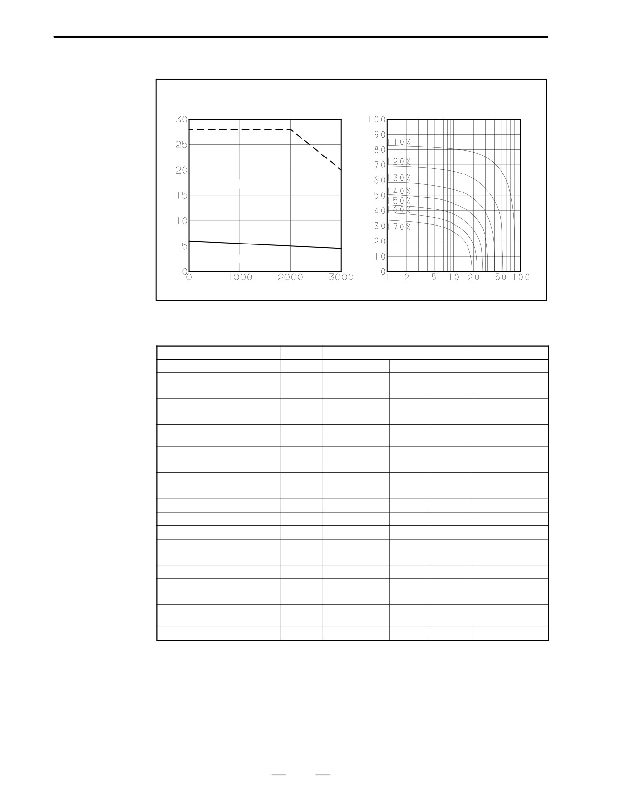
Model αC6/2000
Specification : A06B-0126-Bjjj
Torque
Duty
Speed - torque characteristics
Over load duty
(Nm)
(time %)
Intermittent operating
Continuous operating
Speed (1/min)
”ON” time (min.)
Data sheet
Parameter
Symbol
Value
Unit
Rating output speed
Nmax
2000
min -1
6. 0
Nm
Rated torque at stall
(*)
Ts
61
kgfcm
0. 0026
kgm2
Rotor inertia
Jm
0. 027
kgfcms2
Continuous RMS current at stall
Is
3. 6
A (rms)
(*)
1. 68
Nm/A (rms)
Torque constant
(*)
Kt
17. 1
kgfcm/A (rms)
Back EMF constant
(*)
Ke
59
V/1000min -1
(*)
Kv
0. 56
Vsec/rad
Armature resistance
(*)
Ra
1. 52
Ω
Mechanical time constant
(*)
tm
0. 004
s
Thermal time constant
tt
50
min
0. 3
Nm
Static friction
Tf
3
kgfcm
Maximum allowable current
Im
47
A (peak)
56
Nm
Maximum theoretical torque
Tm
570
kgfcm
Maximum theoretical
21000
rad/s2
acceleration
Weight
13
kg
(*) The values are the standard values at 20°C and the tolerance is "10%.
The speed-torque characteristics very depending on the type of software, parameter
setting, and input voltage of the digital servo motor. (The above figures show average
values.) These values may be changed without prior notice.
159
3.SPECIFICATIONS AND
CHARACTERISTICS
FANUC AC SERVO MOTOR αC series
B-65142E/02
Model αC12/2000
Specification : A06B-0141-Bjjj
Torque
Duty
(Nm)
Speed - torque characteristics
(time %)
Over load duty
Intermittent operating
Continuous operating
Speed (1/min)
”ON” time (min.)
Data sheet
Parameter
Symbol
Value
Unit
Rating output speed
Nmax
2000
min -1
12
Nm
Rated torque at stall
(*)
Ts
122
kgfcm
0. 0062
kgm2
Rotor inertia
Jm
0. 064
kgfcms2
Continuous RMS current at stall
Is
5. 9
A (rms)
(*)
2. 04
Nm/A (rms)
Torque constant
(*)
Kt
20. 8
kgfcm/A (rms)
Back EMF constant
(*)
Ke
71
V/1000min -1
(*)
Kv
0. 68
Vsec/rad
Armature resistance
(*)
Ra
1. 092
Ω
Mechanical time constant
(*)
tm
0. 005
s
Thermal time constant
tt
60
min
0. 8
Nm
Static friction
Tf
8
kgfcm
Maximum allowable current
Im
46
A (peak)
66
Nm
Maximum theoretical torque
Tm
670
kgfcm
Maximum theoretical
11000
rad/s2
acceleration
Weight
18
kg
(*) The values are the standard values at 20°C and the tolerance is "10%.
The speed-torque characteristics very depending on the type of software, parameter
setting, and input voltage of the digital servo motor. (The above figures show average
values.) These values may be changed without prior notice.
160
3. SPECIFICATIONS AND
B-65142E/02
FANUC AC SERVO MOTOR αC series
CHARACTERISTICS
Model αC22/1500
Specification : A06B-0145-Bjjj
Torque
Duty
(Nm)
Speed - torque characteristics
(time %)
Over load duty
Intermittent operating
ÂÂÂÂÂÂÂ
Continuous operating
ÂÂÂÂÂÂÂ
Speed (1/min)
”ON” time (min.)
Data sheet
Parameter
Symbol
Value
Unit
Rating output speed
Nmax
1500
min -1
22
Nm
Rated torque at stall
(*)
Ts
224
kgfcm
0. 012
kgm2
Rotor inertia
Jm
0. 12
kgfcms2
Continuous RMS current at stall
Is
12. 5
A (rms)
(*)
1. 76
Nm/A (rms)
Torque constant
(*)
Kt
18. 0
kgfcm/A (rms)
Back EMF constant
(*)
Ke
62
V/1000min -1
(*)
Kv
0. 59
Vsec/rad
Armature resistance
(*)
Ra
0. 315
Ω
Mechanical time constant
(*)
tm
0. 004
s
Thermal time constant
tt
65
min
1. 2
Nm
Static friction
Tf
12
kgfcm
Maximum allowable current
Im
105
A (peak)
130
Nm
Maximum theoretical torque
Tm
1400
kgfcm
Maximum theoretical
11000
rad/s2
acceleration
Weight
30
kg
(*) The values are the standard values at 20°C and the tolerance is "10%.
The speed-torque characteristics very depending on the type of software, parameter
setting, and input voltage of the digital servo motor. (The above figures show average
values.) These values may be changed without prior notice.
161
3.SPECIFICATIONS AND
CHARACTERISTICS
FANUC AC SERVO MOTOR αC series
B-65142E/02
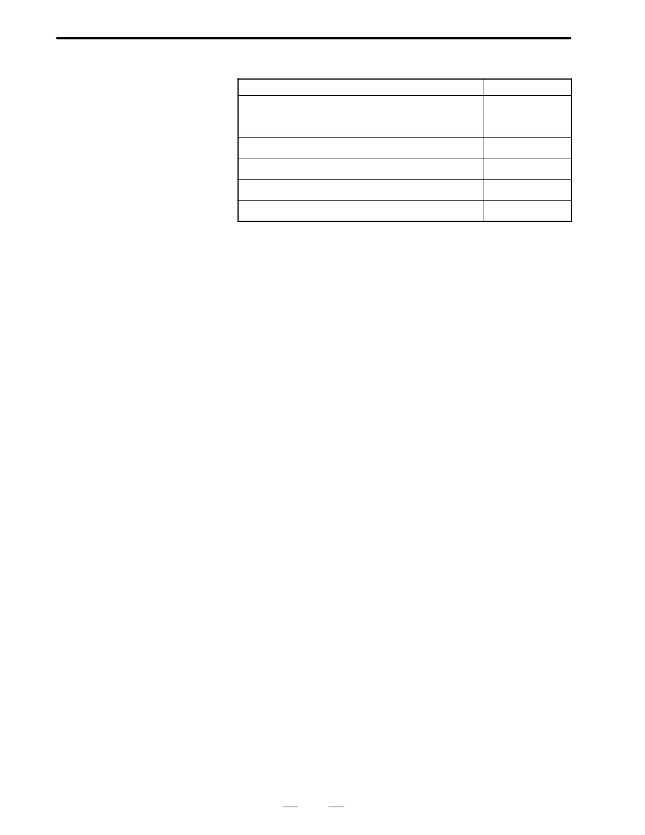
3.3
OUTLINE DRAWINGS
Model
Fig. No.
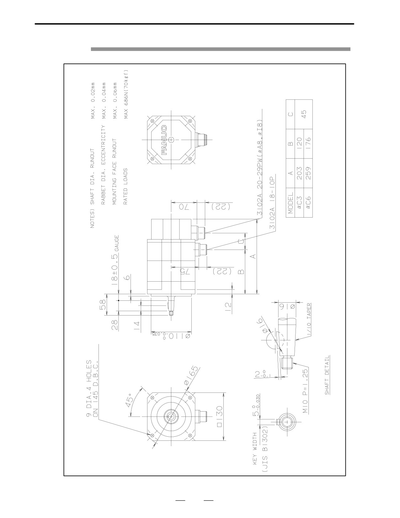
Models αC3/2000 and αC6/2000
Fig. 3.3(a)
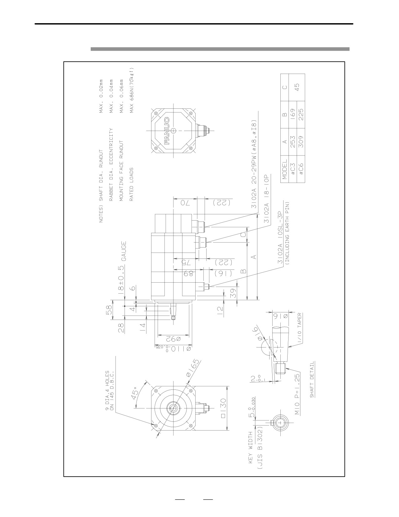
Models αC3/2000 and αC6/2000 (with the brake)
Fig. 3.3(b)
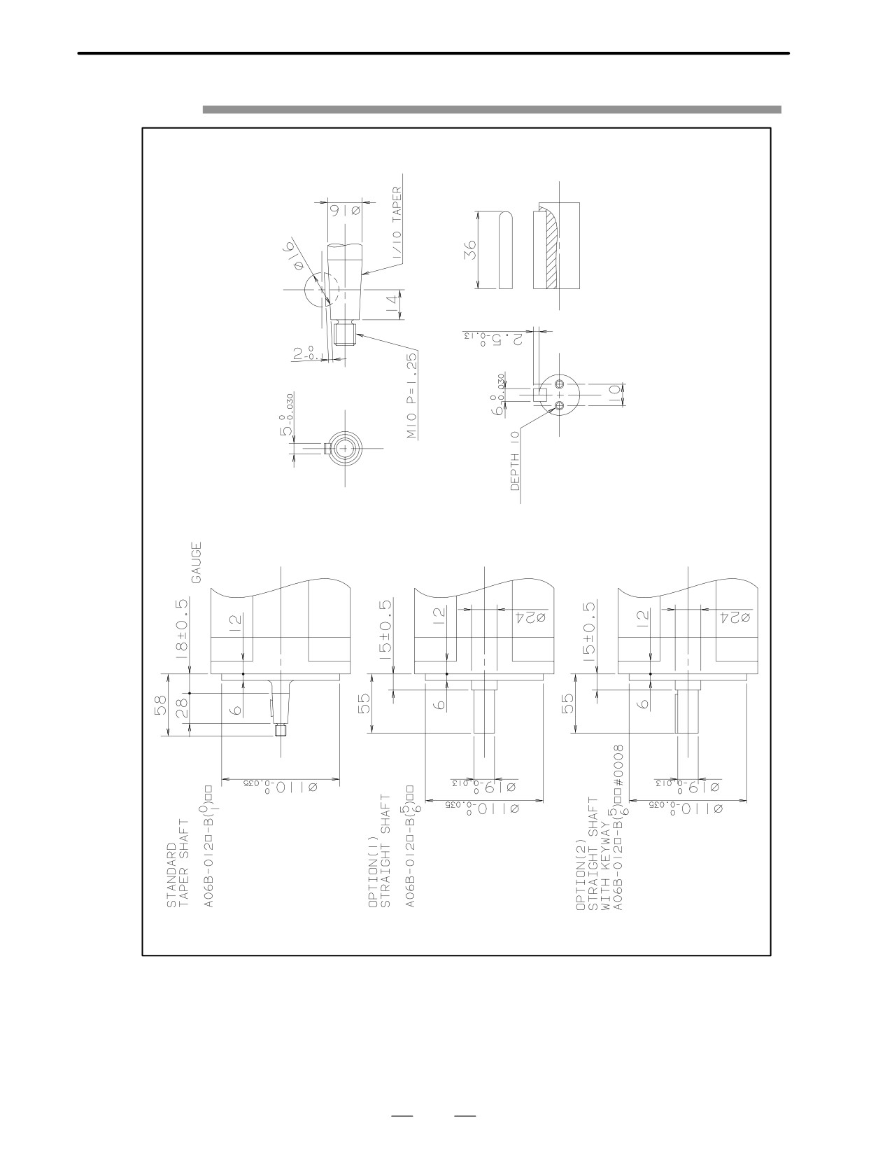
Models αC3/2000 and αC6/2000 (shaft option)
Fig. 3.3(c)
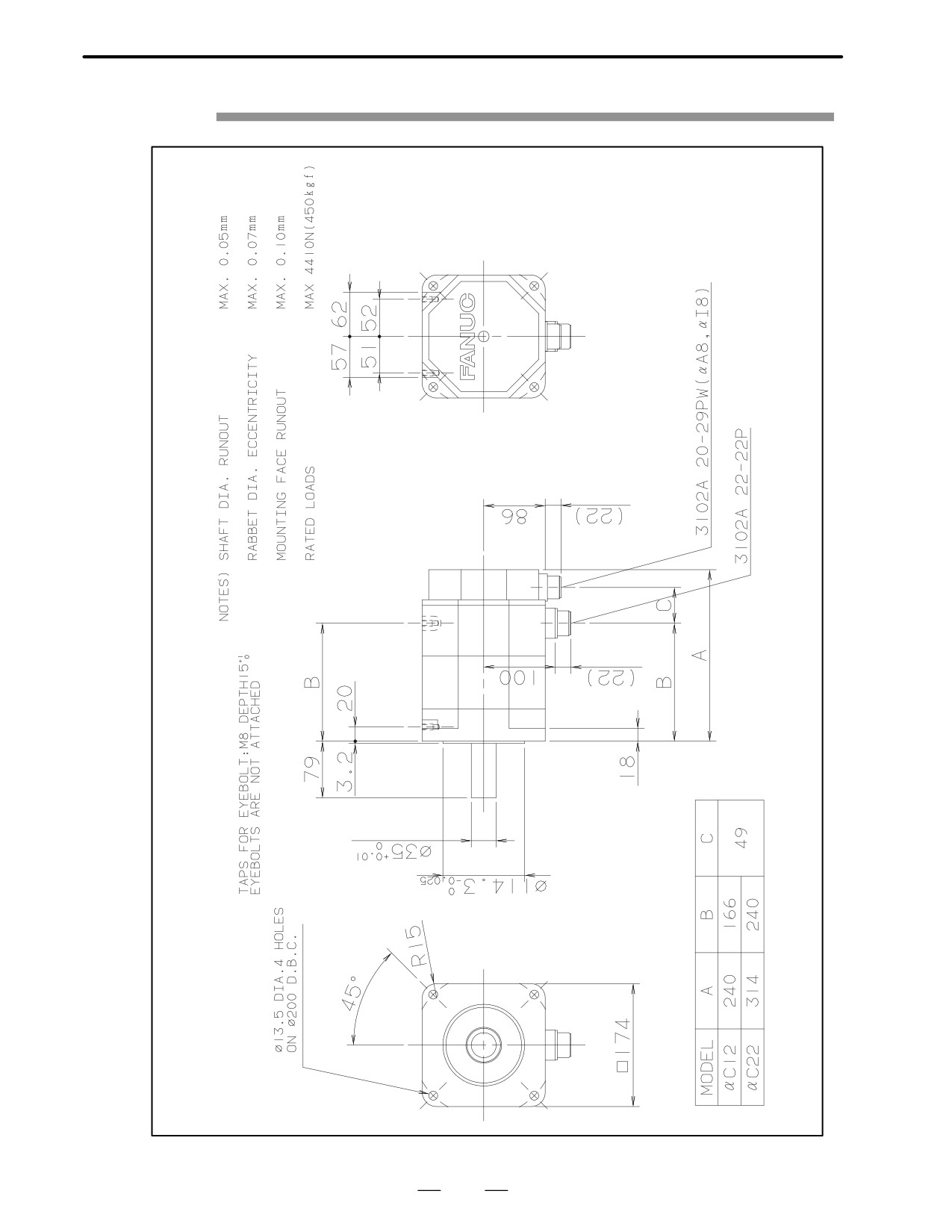
Models αC12/2000 and αC22/1500
Fig. 3.3(d)
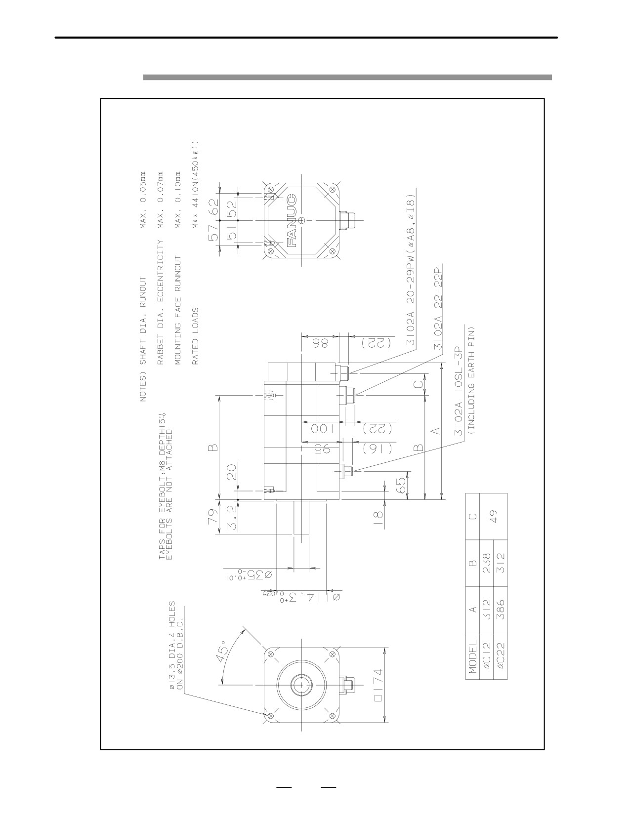
Models αC12/2000 and αC22/1500 (with the brake)
Fig. 3.3(e)
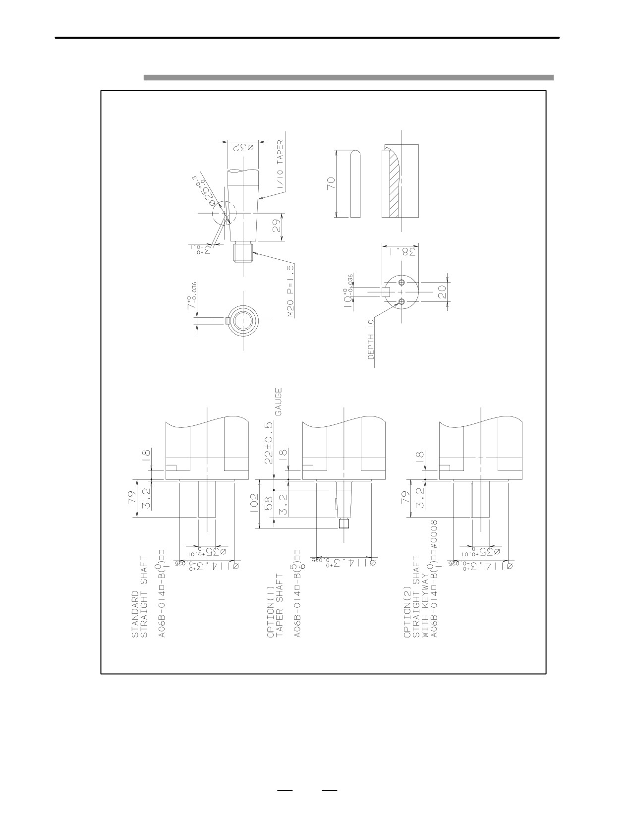
Models αC12/2000 and αC22/1500 (shaft option)
Fig. 3.3(f)
162
3. SPECIFICATIONS AND
B-65142E/02
FANUC AC SERVO MOTOR αC series
CHARACTERISTICS
Fig. 3.3 (a)Models αC3/2000 and αC6/2000
163
3.SPECIFICATIONS AND
CHARACTERISTICS
FANUC AC SERVO MOTOR αC series
B-65142E/02
Fig. 3.3 (b)Models αC3/2000 and αC6/2000 (with the brake)
164
3. SPECIFICATIONS AND
B-65142E/02
FANUC AC SERVO MOTOR αC series
CHARACTERISTICS
Fig. 3.3 (c)Models αC3/2000 and αC6/2000 (shaft option)
165
3.SPECIFICATIONS AND
CHARACTERISTICS
FANUC AC SERVO MOTOR αC series
B-65142E/02
Fig. 3.3 (d)Models αC12/2000 and αC22/1500
166
3. SPECIFICATIONS AND
B-65142E/02
FANUC AC SERVO MOTOR αC series
CHARACTERISTICS
Fig. 3.3 (e)Models αC12/2000 and αC22/1500 (with the brake)
167
3.SPECIFICATIONS AND
CHARACTERISTICS
FANUC AC SERVO MOTOR αC series
B-65142E/02
Fig. 3.3 (f)Models αC12/2000 and αC22/1500 (shaft option)
168
3. SPECIFICATIONS AND
B-65142E/02
FANUC AC SERVO MOTOR αC series
CHARACTERISTICS
3.4
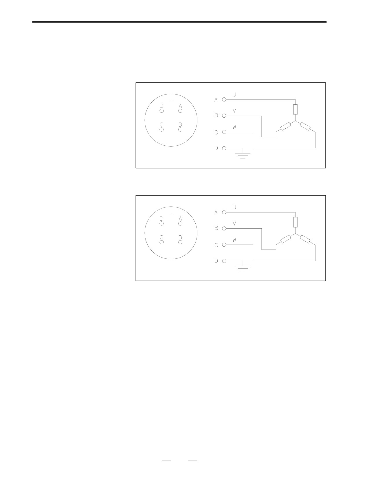
CONNECTION OF
POWER LINE
Models
αC3/2000 and αC6/2000
Motor
coil
Ground plate
3102A 18-10P
Motor body
Models
αC12/2000 and
αC22/1500
Motor
coil
Ground plate
3102A 22-22P
Motor body
169
V. FANUC AC SERVO MOTOR αM series
B-65142E/02
FANUC AC SERVO MOTOR αM series
1. GENERAL
GENERAL
1
The FANUC AC servo motor αM series is suitable for application to the
feed axes of small machine tools. It has the following features:
Excellent acceleration
A high maximum output torque and intermediate rotor inertia result in
characteristics
excellent acceleration characteristics.
Compact
The use of the latest neodymium ferrite magnet further reduces the size
and weight of the servo motors. This produces a servo motor that is
sufficiently compact to allow its use in small machine tools.
Excellent waterproofing
The use of waterproof connectors and FANUC’s unique stator seal
provide excellent waterproofing, ensuring that no liquid, such as coolant,
can enter the motor.
Extended
The use of the latest servo software minimizes the heat generated by
continuous-operation
high-speed rotation, allowing continuous operation over a wide range.
Smooth rotation
Further improvements have been made to the unique magnetic pole shape
to minimize torque ripple. The result is extremely smooth rotation.
Controllability
The use of the latest servo software maintains controllability even when
a disturbance occurs.
High-performance
The AC servo motor αM series are fitted with incremental pulse coder
detector
αI64 or absolute pulse coder αA64 as its standard pulse coder.
Powerful brake
A powerful brake with an increased holding torque is available as an
option. The brake uses an asbestos-free design.
The αM series includes αM3, αM6, and αM9, for which mounting
dimensions are compatible with those for α series models α3 and α6.
173
2.TYPES OF MOTORS
AND DESIGNATION
FANUC AC SERVO MOTOR αM series
B-65142E/02
TYPES OF MOTORS AND DESIGNATION
2
The types and specifications of αM series servo motors are described as
follows.
Models
A06B-01jj-Bl ff
αM3/3000, αM6/3000, and
jj
αM9/3000
61 : Model αM3/3000
62 : Model αM6/3000
63 : Model αM9/3000
l
0 : Taper shaft (standard)
1 : Taper shaft with the brake (8Nm)
5 : Straight shaft
6 : Straight shaft with the brake (8Nm)
ff
75 : With the pulse coder αA64
77 : With the pulse coder αI64
84 : With the serial pulse coder A
The standard shafts used for αM series are taper shafts. Use a taper shaft
as far as circumstances, such as the delivery time and maintenance,
permit.
174
3.SPECIFICATIONS AND
CHARACTERISTICS
FANUC AC SERVO MOTOR αM series
B-65142E/02
3.1
TYPES OF MOTORS
Item
Unit
αM3/3000
αM6/3000
αM9/3000
AND
kW
0.9
1.4
1.8
Output
SPECIFICATIONS
HP
1.3
1.9
2.4
Nm
3.0
6.0
9.0
Rated torque at stall
kgf⋅cm
31
61
92
Rating output speed
1/min
3000
3000
3000
Nm
31
63
130
Maximum theoreti-
cal torque
kgf⋅cm
320
650
1300
2
kg⋅m
0.0007
0.0013
0.0025
Rotor inertia
kgf⋅cm⋅s2
0.008
0.014
0.026
Maximum theoreti-
rad/s2
42000
47000
52000
cal acceleration
Weight
kg
5
8
12
The above values are under the condition at 20°C.
Note
The above values shown in the maximum theoretical torque
are the theoretical values.
The actual maximum torque is restricted by the current limit
values of the drive amplifier.
176
3. SPECIFICATIONS AND
B-65142E/02
FANUC AC SERVO MOTOR αM series
CHARACTERISTICS
3.2
CHARACTERISTIC
CURVE AND DATA
SHEET
Speed-torque
The intermittent operation zone is determined by the input voltage
characteristics
applied to the drive amplifier. The curve shown is the value for the rated
input voltage (200V).
Overload duty
The overload duty characteristic curves are determined based on the
characteristic
temperature restriction for the single motor unit (the temperature is
restricted by means of a thermal trip built into the motor). The curves are
determined by assuming that the temperature increases gradually under
certain overload conditions. Therefore, the curves do not apply to the
rapid temperature rise which occurs, for example, when the motor shaft
is locked. (An overcurrent flows in the motor windings until the thermal
trip operates. The temperature rises momentarily.)
To detect such an abrupt temperature rise, the FANUC digital servo
system provides a software thermal function that uses servo software to
observe the current. During operation that is characterized by frequent
acceleration/deceleration cycles, control is imposed by the software
thermal function.
Driving units (such as amplifiers) and built-in detectors contain their own
overheating protection devices. Therefore, note that control may be
imposed according to how the equipment is being used.
Data sheet
The parameters given in the data sheet are representative values for an
ambient temperature of 20°C. They are subject to an error of +10%.
The indicated logical values are threshold values for the single motor unit
(when the motor is not restricted by the control system).
The maximum torque that can be produced during acceleration or
deceleration in actual use is calculated as the approximate product of the
motor torque constant and the current limit value of the amplifier.
This value is for reference only. The actual value will vary depending on
changes in the power supply, as well as variations in motor parameters and
amplifier limit values.
In some models, if the maximum current flows in the motor, the actual
maximum torque is affected by, for example, magnetic saturation. As a
result, the actual maximum torque will be lower than the calculated value.
The intermittent operation area (maximum torque value) indicated in the
speed to torque characteristics is the effective value, determined
according to the combination with the amplifier.
177
3.SPECIFICATIONS AND
CHARACTERISTICS
FANUC AC SERVO MOTOR αM series
B-65142E/02
Model αM3/3000
Specification : A06B-0161-Bjjj
Torque
Duty
(Nm)
Speed - torque characteristics
Over load duty
(time %)
Intermittent operating
ÂÂÂÂÂÂ
Continuous operating
ÂÂÂÂÂÂÂ
Speed (1/min)
”ON” time (min.)
Data sheet
Parameter
Symbol
Value
Unit
Rating output speed
Nmax
3000
min -1
3. 0
Nm
Rated torque at stall
(*)
Ts
31
kgfcm
0. 0007
kgm2
Rotor inertia
Jm
0. 008
kgfcms2
Continuous RMS current at stall
Is
5. 3
A (rms)
(*)
0. 57
Nm/A (rms)
Torque constant
(*)
Kt
5. 8
kgfcm/A (rms)
Back EMF constant
(*)
Ke
20
V/1000min -1
(*)
Kv
0. 19
Vsec/rad
Armature resistance
(*)
Ra
0. 695
Ω
Mechanical time constant
(*)
tm
0. 005
s
Thermal time constant
tt
40
min
0. 3
Nm
Static friction
Tf
3
kgfcm
Maximum allowable current
Im
75
A (peak)
31
Nm
Maximum theoretical torque
Tm
320
kgfcm
Maximum theoretical
42000
rad/s2
acceleration
Weight
5
kg
(*) The values are the standard values at 20°C and the tolerance is "10%.
The speed-torque characteristics very depending on the type of software, parameter
setting, and input voltage of the digital servo motor. (The above figures show average
values.) These values may be changed without prior notice.
178
3. SPECIFICATIONS AND
B-65142E/02
FANUC AC SERVO MOTOR αM series
CHARACTERISTICS
Model αM6/3000
Specification : A06B-0162-Bjjj
Torque
Duty
(Nm)
Speed - torque characteristics
Over load duty
(time %)
ÂÂÂÂÂÂÂ
ntermittent operating
Continuous operating
ÂÂÂÂÂÂÂ
Speed (1/min)
”ON” time (min.)
Data sheet
Parameter
Symbol
Value
Unit
Rating output speed
Nmax
3000
min -1
6. 0
Nm
Rated torque at stall
(*)
Ts
61
kgfcm
0. 0013
kgm2
Rotor inertia
Jm
0. 014
kgfcms2
Continuous RMS current at stall
Is
8. 0
A (rms)
(*)
0. 75
Nm/A (rms)
Torque constant
(*)
Kt
7. 6
kgfcm/A (rms)
Back EMF constant
(*)
Ke
26
V/1000min -1
(*)
Kv
0. 25
Vsec/rad
Armature resistance
(*)
Ra
0. 463
Ω
Mechanical time constant
(*)
tm
0. 003
s
Thermal time constant
tt
45
min
0. 3
Nm
Static friction
Tf
3
kgfcm
Maximum allowable current
Im
120
A (peak)
63
Nm
Maximum theoretical torque
Tm
650
kgfcm
Maximum theoretical
47000
rad/s2
acceleration
Weight
8
kg
(*) The values are the standard values at 20°C and the tolerance is "10%.
The speed-torque characteristics very depending on the type of software, parameter
setting, and input voltage of the digital servo motor. (The above figures show average
values.) These values may be changed without prior notice.
179
3.SPECIFICATIONS AND
CHARACTERISTICS
FANUC AC SERVO MOTOR αM series
B-65142E/02
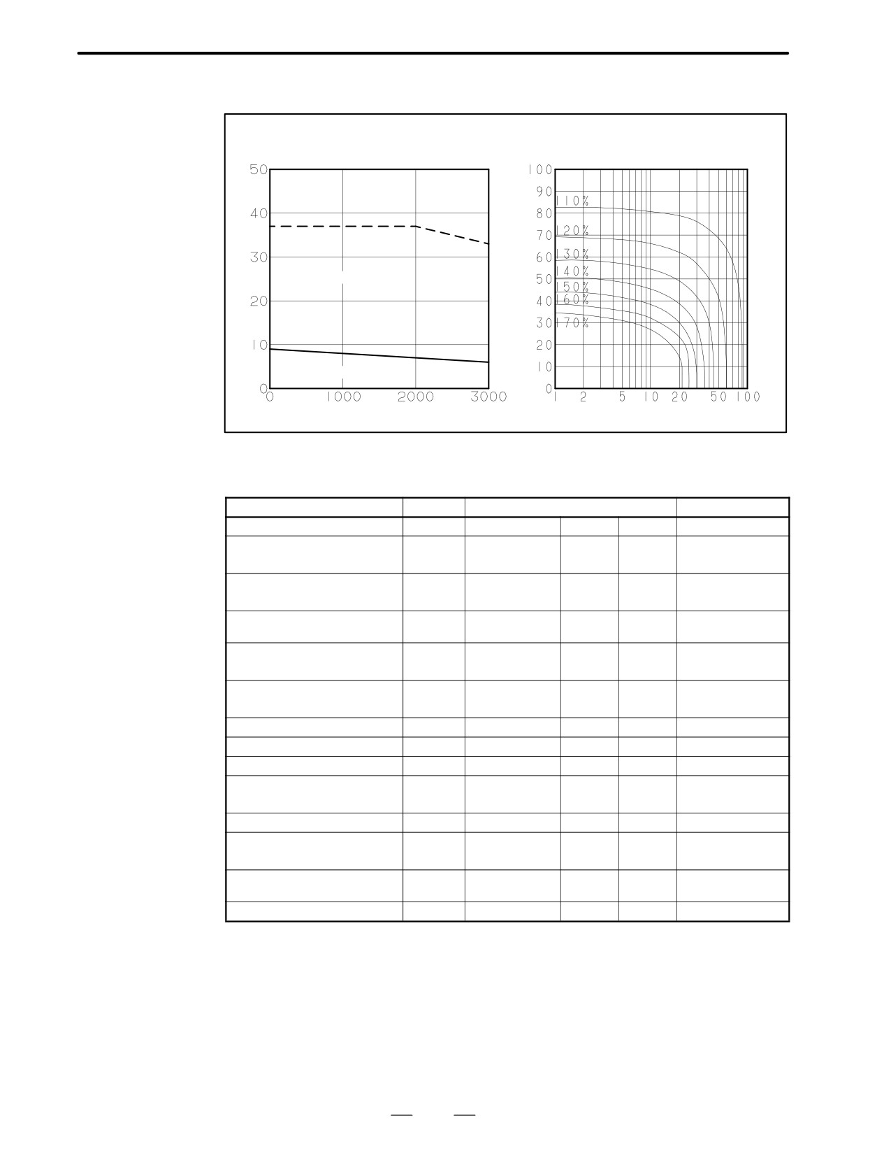
Model αM9/3000
Specification : A06B-0163-Bjjj
Torque
Speed - torque characteristics
Duty
Over load duty
(Nm)
(time %)
Intermittent operating
Continuous operating
ÂÂÂÂÂÂÂ
Speed (1/min)
”ON” time (min.)
Data sheet
Parameter
Symbol
Value
Unit
Rating output speed
Nmax
3000
min -1
9. 0
Nm
Rated torque at stall
(*)
Ts
92
kgfcm
0. 0025
kgm2
Rotor inertia
Jm
0. 026
kgfcms2
Continuous RMS current at stall
Is
10. 4
A (rms)
(*)
0. 86
Nm/A (rms)
Torque constant
(*)
Kt
8. 8
kgfcm/A (rms)
Back EMF constant
(*)
Ke
30
V/1000min -1
(*)
Kv
0. 29
Vsec/rad
Armature resistance
(*)
Ra
0. 181
Ω
Mechanical time constant
(*)
tm
0. 002
s
Thermal time constant
tt
50
min
0. 3
Nm
Static friction
Tf
3
kgfcm
Maximum allowable current
Im
216
A (peak)
130
Nm
Maximum theoretical torque
Tm
1300
kgfcm
Maximum theoretical
52000
rad/s2
acceleration
Weight
12
kg
(*) The values are the standard values at 20°C and the tolerance is "10%.
The speed-torque characteristics very depending on the type of software, parameter
setting, and input voltage of the digital servo motor. (The above figures show average
values.) These values may be changed without prior notice.
180

3. SPECIFICATIONS AND
B-65142E/02
FANUC AC SERVO MOTOR αM series
CHARACTERISTICS
3.3
OUTLINE DRAWINGS
Model
Fig. No.
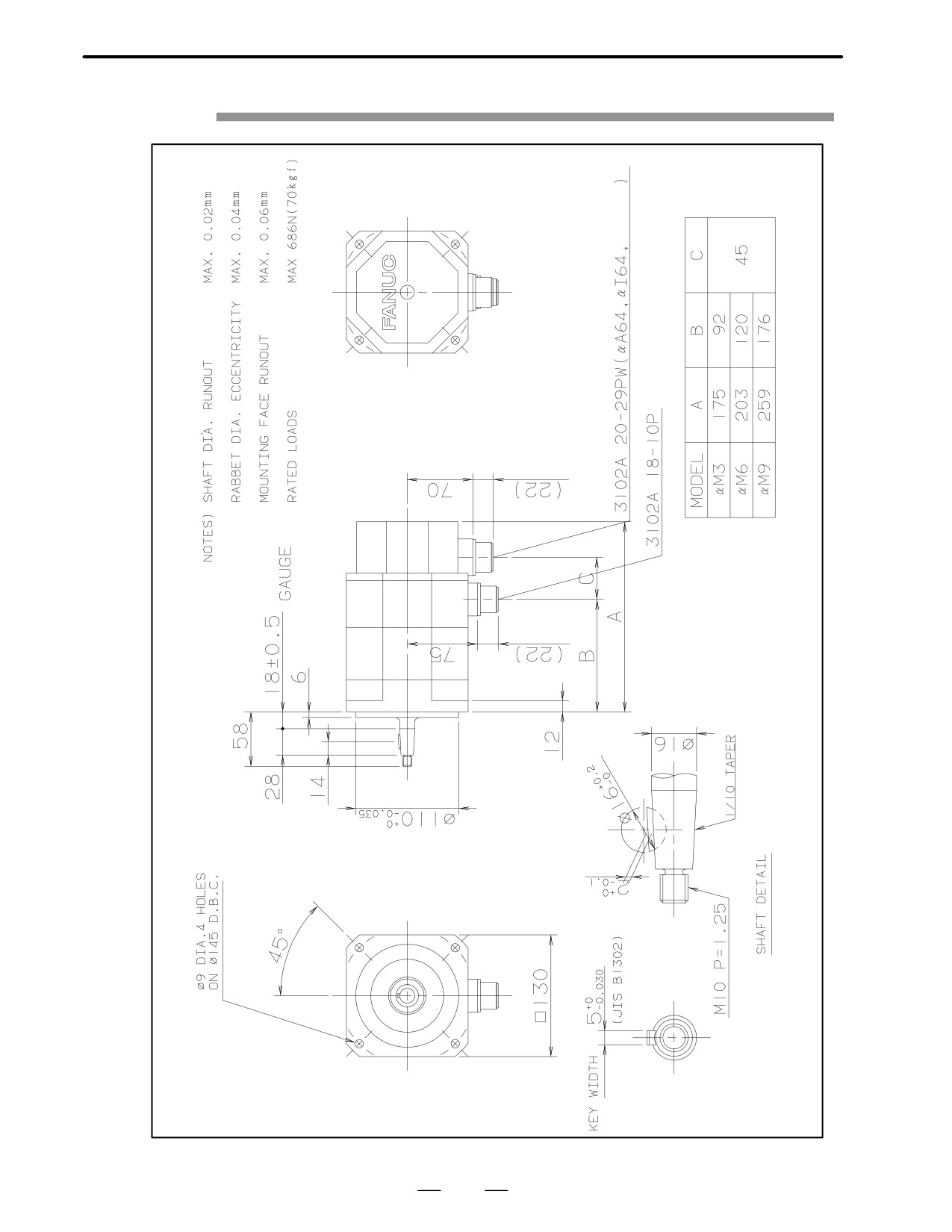
Models αM3, αM6 and αM9
Fig. 3.3 (a)
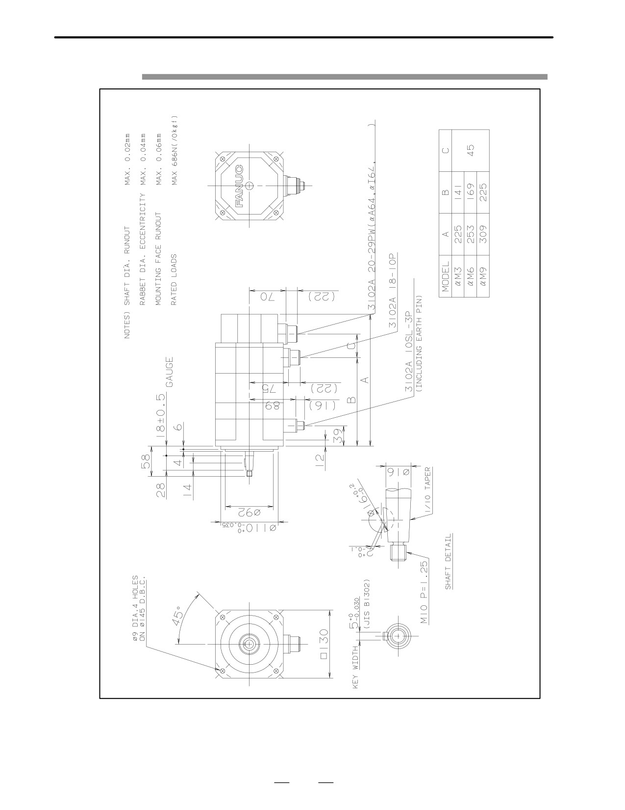
Models αM3, αM6 and αM9 (with the brakeK
Fig. 3.3 (b)
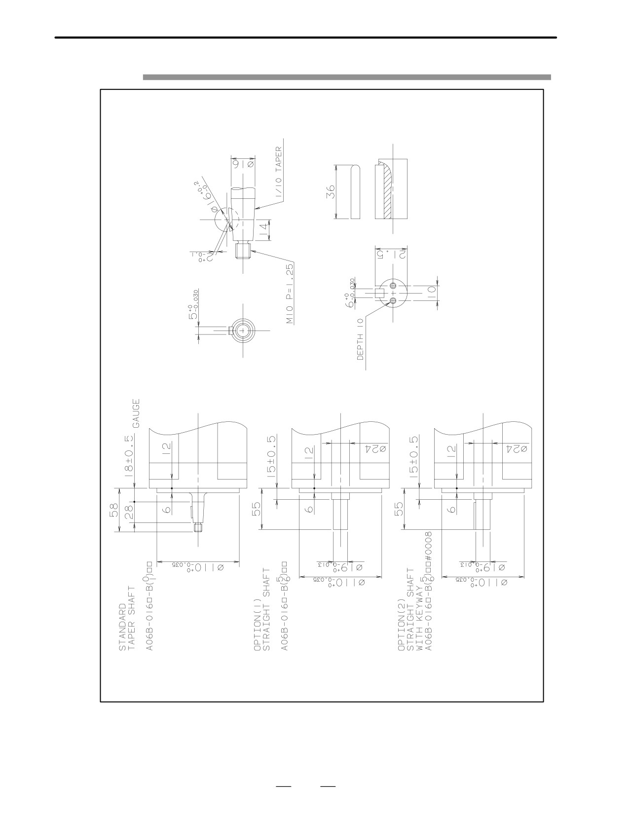
Models αM3 and αM6 (shaft option)
Fig. 3.3 (c)
Model αM9 (shaft option)
Fig. 3.3 (d)
181
3.SPECIFICATIONS AND
CHARACTERISTICS
FANUC AC SERVO MOTOR αM series
B-65142E/02
Fig. 3.3 (a)Models αM3,αM6, and αM9
Serial A
182
3. SPECIFICATIONS AND
B-65142E/02
FANUC AC SERVO MOTOR αM series
CHARACTERISTICS
Fig. 3.3 (b)Models αM3,αM6, and αM9 (with the brake)
Serial A
183
3.SPECIFICATIONS AND
CHARACTERISTICS
FANUC AC SERVO MOTOR αM series
B-65142E/02
Fig. 3.3 (c)Models αM3, and αM6 (shaft option)
184