FANUC a Series AC SERVO MOTOR. Description Manual (GFZ-65142E/02) - page 3
B-65142E/02
DESCRIPTIONS FOR THE α series
6. FEEDBACK DETECTOR
FEEDBACKB DETECTOR
6
57
6. FEEDBACK DETECTDESCRIPTIONS FOR THE α series
B-65142E/02
All AC servo motors feature a pulse coder (optical encoder).
6.1
The pulse coder outputs position information and an alarm signal.
BUILT-IN DETECTOR
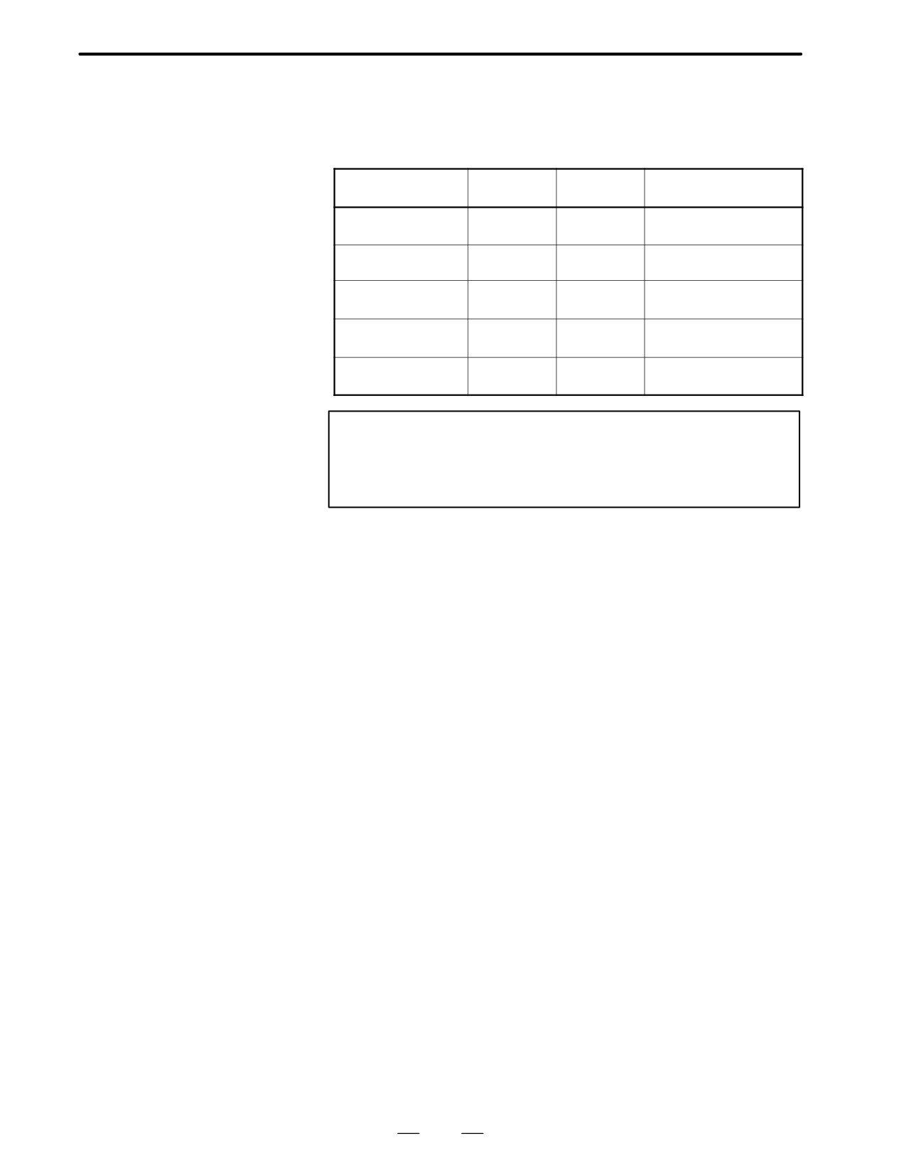
The following lists the available pulse coders, together with their
specifications and the motors with which they are compatible.
Pulse coder type
Resolution
Absolute/
Applicable motor
Division/rev
incremental
Pulse coder αA64
65,536
Absolute
α(HV), αC, αM, αL, and
α series except α0.5
Pulse coder αA8B
8,192
Absolute
α0.5 (Pulse coder is built
into the motor.)
Pulse coder αI64
65,536
Incremental
α(HV), αC, αM, αL, and
α series except α0.5
Pulse coder αI8B
8,192
Incremental
α0.5 (Pulse coder is built
into the motor.)
Pulse coder A
1,000,000
Absolute
α(HV), αM, αL, and α
series except α0.5
Note
The pulse coders listed above can be connected to an NC
if the NC is fitted with the serial pulse coder interface, and
the digital servo software for the α pulse coders is installed.
58
B-65142E/02
DESCRIPTIONS FOR THE α series
6. FEEDBACK DETECTOR
6.2
PULSE CODER
RESOLUTION AND
CONTROL
RESOLUTION
65,536
With the NC’s flexible feed gear function, 1-µm control can be performed
divisions/revolution
for feed pitches of up to 30 mm per motor revolution.
Note that, however, that this function is subject to a rounding error of
1/65,536 revolution exists.
8,192
This pulse coder is suitable for applications that require a precision of
divisions/revolution
about 2 µm, which tend to correspond to feed pitches up to about 12 mm
per motor revolution.
Although 1-µm control can be set, note that this is subject to a rounding
error of 1/8,192 revolution. If 1-µm control is performed with a feed pitch
exceeding 8 mm per motor revolution, the motor may not be stable when
stopped. In such a case, it is recommended that CMR be set to 1/2, and
the detection unit to 2 µm.
1,000,000
With the NC’s flexible feed gear function 0.1-µm control (up to 100
divisions/revolution
mm/revolution) and 0.01-µm control (up to 10 mm/revolution) can be
performed.
59
6. FEEDBACK DETECTDESCRIPTIONS FOR THE α series
B-65142E/02
When the NC is turned off, the pulse coder position detection function is
6.3
backed up by battery. So, when the NC is next turned on, the operator does
ABSOLUTE-TYPE
not have to perform reference position return.
PULSE CODER
For backup, a battery unit must be installed in the NC or servo amplifier.
If a low-battery indication appears on the NC, renew the battery as soon
as possible.
Replace the battery while the NC is turned on.
60
B-65142E/02
DESCRIPTIONS FOR THE α series
6. FEEDBACK DETECTOR
For detecting a position by attaching directly to a ball screw or a machine,
6.4
use a separate type position detector. Pay attention to the following items
SEPARATE TYPE
when using the separate type position detector.
POSITION
Increase the machine rigidity between the servo motor and the position
DETECTOR
detector to minimize mechanical vibration. If the machine rigidity is
low or the structure vibrates, poor performance is likely to occur.
Generally, when the separate type detector is used, the influence of
gear, ball screw pitch error or table inclination is decreased and the
positioning accuracy and geometrical accuracy (roundness, etc.) are
increased, but the smoothness may deteriorate due to the elasticity in
the machine between the servo motor and the position detector.
It is necessary to use the built-in pulse coder with a resolution equal
to or finer than that of the separate type position detector.
To connect the separate type position detector to the NC, connect only the
signals described in the connecting manual.
(A, B, Z, 0V, 5V and REQ
if necessary)
When the other signal is connected, the unit may malfunction.
Do not connect the C1, C2, C4, and C8 signals output from the separate
type pulse coder unit.
FANUC provides the following external position (rotary) detector.
Pulse coder unit
Available in the following specifications. The feature and restrictions on
the feed rate, etc. are the same those of the built-in pulse coder.
Incremental pulse coder
A860-0301-T0jj
unit
jj
01 : 2000P/rev (Up to 3000min -1)
02 : 2500P/rev (Up to 2400min -1)
03 : 3000P/rev (Up to 2000min -1)
04 : 4000P/rev (Up to 1500min -1)
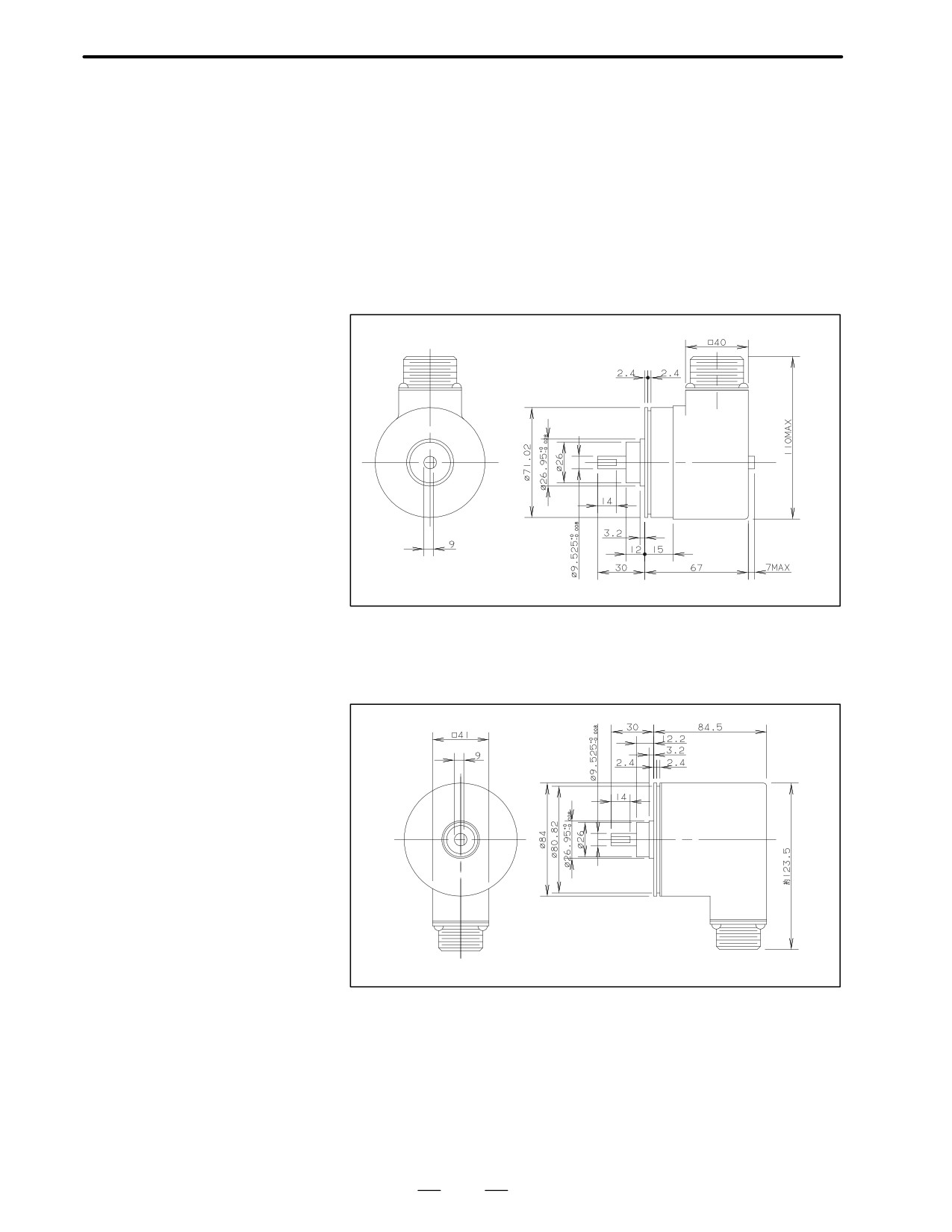
The dimensions are given in “Pulse Coder Unit Outside Dimensions” in
this section.
Absolute pulse coder
A860-0324-T1jj
unit
jj
01 : 2000P/rev (Up to 3000min -1)
02 : 2500P/rev (Up to 2400min -1)
03 : 3000P/rev (Up to 2000min -1)
04 : 4000P/rev (Up to 1500min -1)
The dimensions are given in “Pulse Coder Unit Outside Dimensions” in
this section.
61
6. FEEDBACK DETECTDESCRIPTIONS FOR THE α series
B-65142E/02
High-speed high
A860-0314-T1jj
resolution pulse coder
unit
jj
11 : 20000/rev (Up to 3000min -1)
12 : 25000/rev (Up to 2400min -1)
13 : 30000/rev (Up to 2000min -1)
Pulse coder unit outside
dimensions
Incremental pulse coder
unit
Absolute pulse coder
unit
High-speed high
resolution pulse coder
unit
62
B-65142E/02
DESCRIPTIONS FOR THE α series
6. FEEDBACK DETECTOR
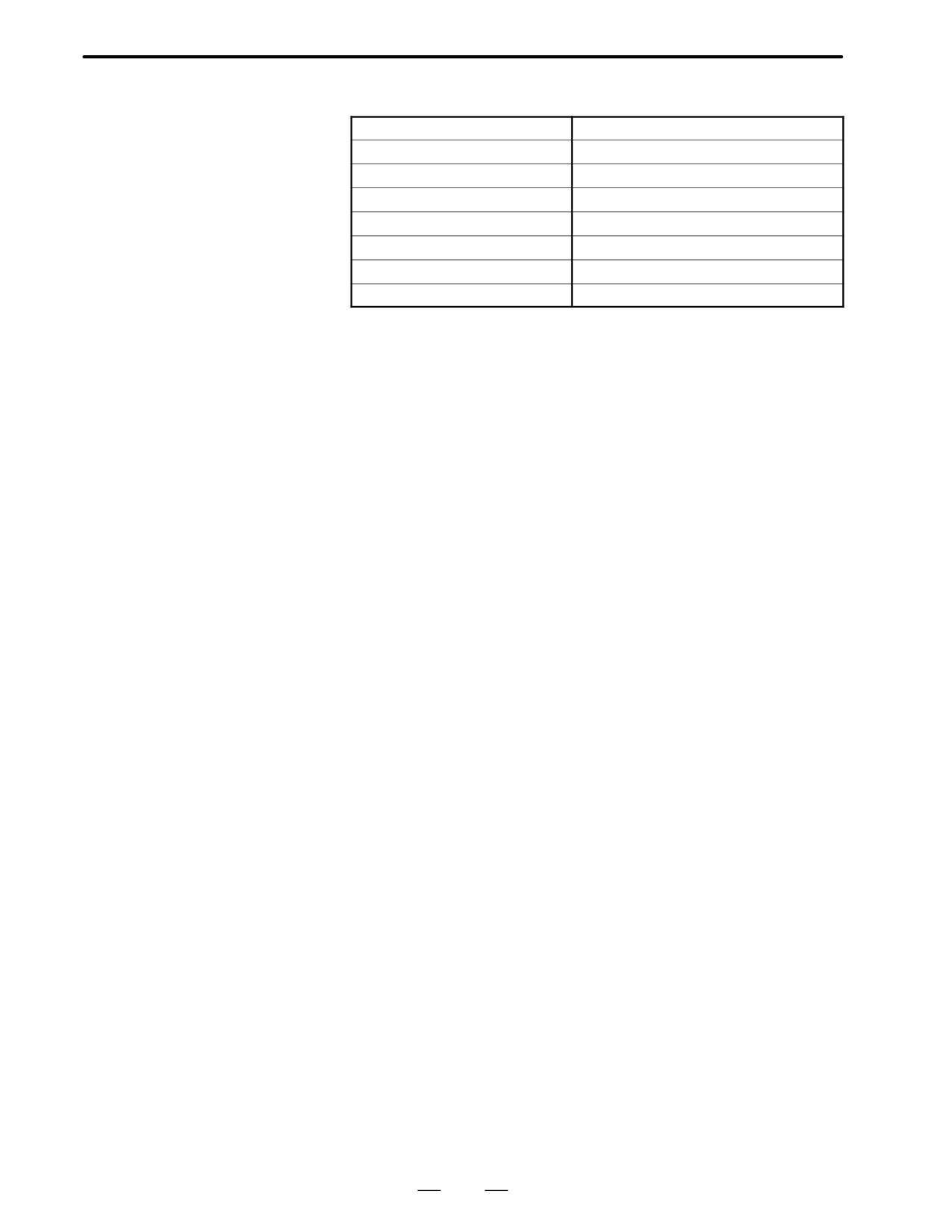
Pulse coder unit
specifications
Power supply
5V"5%, 0.35A or less
Maximum pulse rate
100KHz
Working temperature range
0°C to 60 °C
Rated loads
Radial 2.0kg, Axial 1.0kg
Shaft diameter runout
0.02mm
Weight
2.0kg
Rotor inertia
Max. 0.057g·cm·sec2
Friction torque
Max. 0.8kg·cm
63
6. FEEDBACK DETECTDESCRIPTIONS FOR THE α series
B-65142E/02
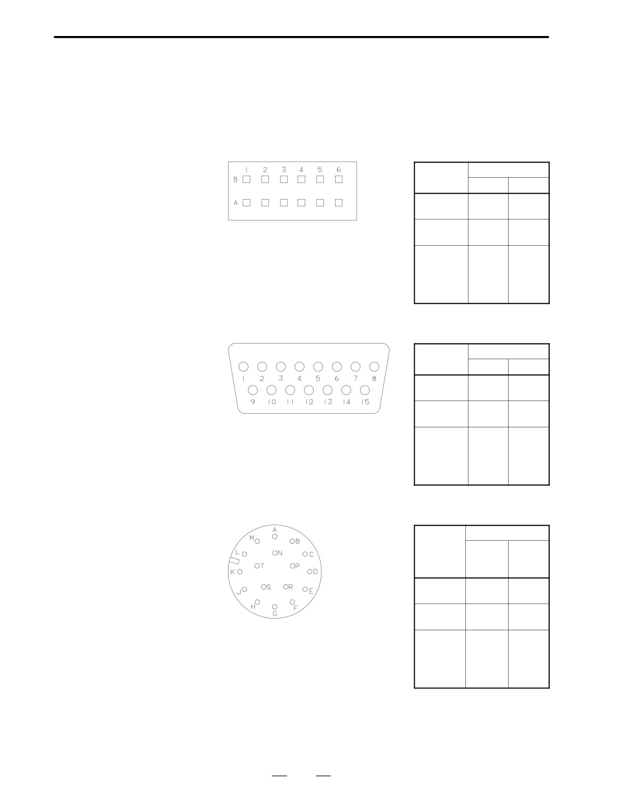
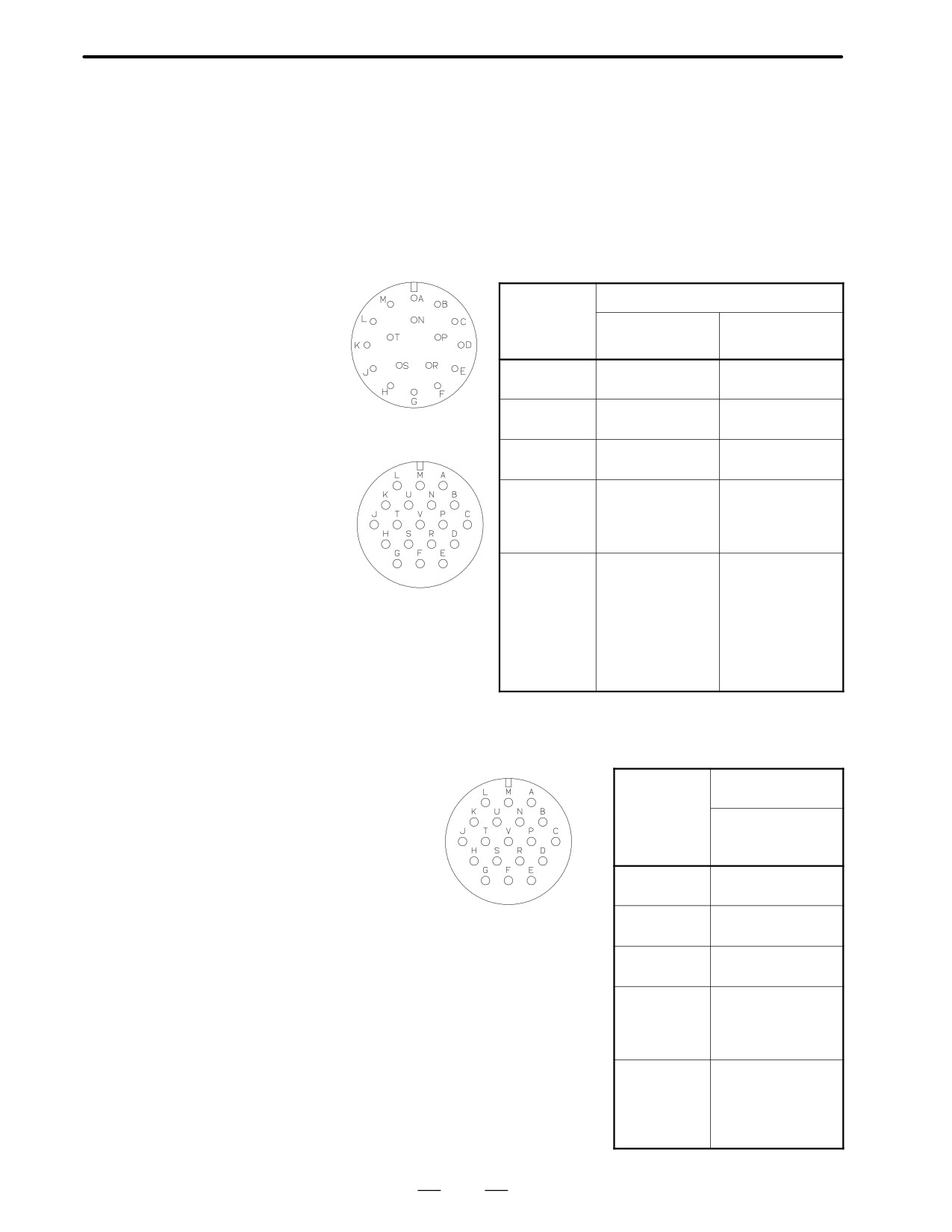
The α-type pulse coders signals are inputed or outputed as shown below.
6.5
The pin assignments of the signals for the connector used for each model
DETECTOR
are also shown. (The output signals and pin assignments for serial pulse
INPUT/OUTPUT
coder A are the same as those for the α-type pulse coder.)
SIGNALS
Model
α0.5/3000
Signal
Pin No.
name
αA8B
αI8B
SD
A4
A4
*SD
B4
B4
REQ
A3
A3
Dynamic D-3100D
*REQ
B3
B3
Free hanging type
(Manufactured by AMP Japan;
+5V
A2, B2
A2, B2
178964-6)
0V
A1, B1
A1, B1
Shield
B6
B6
Mating cable connector housing
+6VA
A5
-
specifications
0VA
A6
-
(Manufactured by AMP Japan;
178289-6)
Models
α1/3000, α2/2000,
Signal
Pin No.
α2/3000
name
αA64
αI64
SD
12
12
*SD
13
13
REQ
5
5
*REQ
6
6
D-SUB 15P
+5V
8, 15
8, 15
0V
1, 2, 3
1, 2, 3
Shield
4
4
+6VA
14
-
0VA
10
-
Models
α3/3000 to α150/2000
Pin No.
α3/3000HV to α30/3000HV
Signa
l
αA64
αI64
αC3/2000 to αC22/1500
name
αA8
αI8
αM3/3000 to αM9/3000
SerialA
αL3/3000 to αL50/3000
SD
A
A
*SD
D
D
REQ
F
F
*REQ
G
G
3102A 20-29PW
+5V
J, K
J, K
0V
N, T
N, T
Shield
H
H
+6VA
R
-
0VA
S
-
64
B-65142E/02
DESCRIPTIONS FOR THE α series
6. FEEDBACK DETECTOR
The separate-type detector signals are inputted or outputted as follows:
6.6
SIGNALS
INPUT/OUTPUT
FROM
SEPARATE-TYPE
DETECTOR
Separate type
incremental absolute
Signal
Pin names of the connector
pulse coder unit
names of
Incremental
Absolute
the pulse
310A20-29P
3102A22-14P
coder
A
A
A
*A
D
B
B
B
C
3102A20-29P
*B
E
D
Z
F
E
*Z
G
F
C1
-
G
C2
-
H
C4
-
J
C8
-
K
+5V
C, J, K
L
0V
N, P, T
M
3102A22-14P
shield
H
N
OH1
-
-
OH2
-
-
REQ
-
S
+6VA
-
T
0VA
-
U
Separate type
high-speed and
Pin names of the
high-resolution pulse
Signal
connector
names of
coder unit
the pulse
High-speed and
high-resolution
coder
3102A22-14P
A
A
AR
B
B
C
3102A22-14P
BR
D
Z
E
*Z
F
C1
G
C2
H
C4
J
C8
K
+5V
L, T
0V
M, U
Shield
N
OH1
-
OH2
-
65
7. BUILT-IN BRAKE
DESCRIPTIONS FOR THE α series
B-65142E/02
BUILT-IN BRAKE
7
Some of the α, α(HV), αC, αM, and αL series Models use motors that
contain a holding brake to prevent falling along a vertical axis.
Motors with a built-in brake have different outlines and weight from other
types of motors. For their outlines, refer to appropriate outline drawings.
66
B-65142E/02
DESCRIPTIONS FOR THE α series
7. BUILT-IN BRAKE
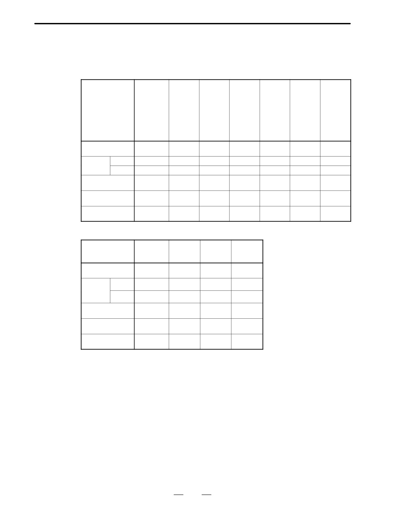
The specifications of built-in brakes are listed below.
7.1
BRAKE
SPECIFICATIONS
α3
α12
α6
α22
α3HV
α30
α6HV
α65
α1
α12HV
Motor model
Unit
α0.5
αC3
α40
α100
α2
α22HV
αC6
α150
α30HV
αM3
αC12
αM6
αC22
αM9
Nm
0.65
2
8
35
35
100
Brake torque
kgf⋅cm
6.6
20
82
357
357
1020
Release
msec
40
60
80
150
150
150
Response
time
Brake
msec
20
10
40
20
20
20
Supply voltage
VDC("10%)
90
90
90
90
90
90
Current
A
0.1 or less
0.3 or less
0.4 or less
0.6 or less
0.6 or less
0.9 or less
kg
Approx.
Approx.
Approx.
Approx.
Approx.
Approx.
Weight increase
0.4kg
1.3kg
2.3kg
6.3kg
10kg
15kg
kg⋅m
2
0.000009
0.00002
0.00007
0.0006
0.0010
0.0010
Inertia increase
kgf⋅cm⋅s2
0.00009
0.0002
0.0007
0.006
0.010
0.010
αL3
αL25
αL25
Motor model
Unit
αL6
αL50
αL50
αL9
Nm
8
18
40
Brake torque
kgf⋅cm
82
184
408
Response
msec
80
100
130
Release
time
Brake
msec
40
60
60
Supply voltage
VDC("10%)
90
90
90
Current
A
0.4 or less
0.6 or less
0.8 or less
kg
Approx.
Approx.
Approx.
Weight increase
2.3kg
6.0kg
7.0kg
2
kg⋅m
0.00007
0.0006
0.0006
Inertia increase
kgf⋅cm⋅s2
0.0007
0.006
0.006
67
7. BUILT-IN BRAKE
DESCRIPTIONS FOR THE α series
B-65142E/02
Common notes to each
series
Notes
1. Use the full-wave rectified 100VAC or 90VDC as a power
supply. Don’t use the half-wave rectified 200VAC. The
surge suppressor may be damaged.
Use a rectifier with dielectric strength of 400V or higher.
Connect CR as shown in the drawing, to protect the contact
of the switch.
2. This brake is used to hold the machine when the servo
motor control is turned off. It is possible to brake the
machine by turning off the brake power at emergency stop
such as at the stroke end, but it is impossible to use this
brake to reduce the stop distance in normal operation.
3. Allow sufficient time to start the servo motor before
releasing the brake. Don’t use the brake as an aid for the
axis to stop at the same position for a long time, such as an
index table. Turn the servo off when holding the axis by the
built-in brake or another holding means. At this time, allow
sufficient time to set the brake before turning off the servo.
4. Models α40/2000 are longer because they contain a brake.
If an excessive load is applied to the opposite side of the
flange, the flange may be damaged. Do not apply any load
to the opposite side of the flange, and do not subject the
motor to excessive force.
68
B-65142E/02
DESCRIPTIONS FOR THE α series
7. BUILT-IN BRAKE
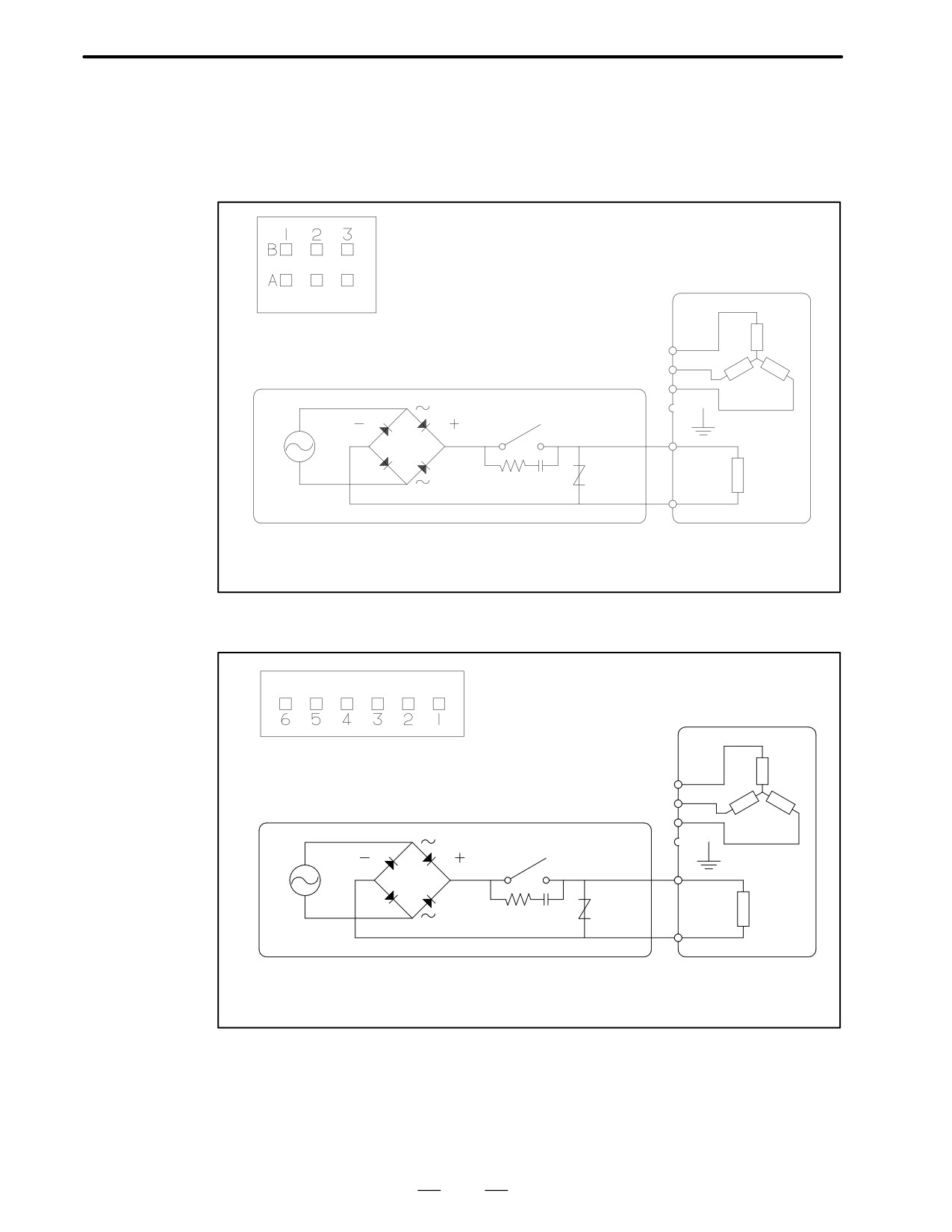
The example of the connection of the brakes are as follows.
7.2
CONNECTION OF
THE BRAKES
Model
α0.5
Dynamic D-3200M
Free Hanging Type
(Manufactured by AMP
Ltd. 3-179554-3)
U
Motor
coil
A1
V
W
Magnetics cabinet
A2
A3
Grounding plate
B1
500VDC
Surge
Motor body
absorber
B2
Brake
500Ω/0.2µF
coil
100VAC
B3
Surge absorber: Manufactured by Matsushita Electronic Parts Ltd.
ERZ-C20DK221, ERZ-C10DK221 or equivalent
Models
α1gand α2
(Manufactured by AMP Ltd.
176339-2)
U
Motor
coil
1
V
W
Magnetics cabinet
2
3
Grounding plate
4
500VDC
Surge
absorber
Motor body
5
Brake
500Ω/0.2µF
coil
100VAC
6
Surge absorber: Manufactured by Matsushita Electronic Parts Ltd.
ERZ-C20DK221, ERZ-C10DK221 or equivalent
69
7. BUILT-IN BRAKE
DESCRIPTIONS FOR THE α series
B-65142E/02
Models
α3 to α150, αC, αM, and
αL
A
C A
Brake
90VDC
Surge
coil
suppressor
B
B
Grounding plate
3102A 10SL-3P
C
Motor body
Magnetics cabinet
500VDC
Motor
A
Surge
Brake
500Ω/0.2µF
suppressor
coil
B
100VAC
C
Ground plate
Motor body
70
B-65142E/02
DESCRIPTIONS FOR α series
8. CONNECTORS
CONNECTORS
8
71
8. CONNECTORS
DESCRIPTIONS FOR α series
B-65142E/02
The FANUC α series AC servo motors use TÜV-approved connectors
8.1
on the power cable and brake/fan unit in order to comply with the IEC34
CONNECTOR ON
standard. Dripproof receptacle connectors are used as standard for all
THE MOTOR SIDE
cables including those for signals (except for the α0.5, α1, and α2 series).
These connectors are dripproof even when not engaged.
Strictly speaking, the IEC34 for connectors is different from the MS
standard with respect to the connector disengaged-state waterproof
function and appearance (black in color). However, the TÜV-approved
connectors are compatible with the MS-standard round connectors in size
and shape. So, MS-standard plug connectors other than those
recommended below are also usable.
(The waterproof plug connectors
recommended in Sections 8.3.1 and 8.3.2 should be used if it is necessary
to keep the whole system waterproof.)
α0.5 to α2
8.1.1
Specifications of
Motor model
Power cable
Signal cable
Brake circuit cable
Connectors on the
α0.5/3000
3-179554-3
178964-6
The brake circuit
Motor Side
(AMP Japan)
(AMP Japan)
cable should be ac-
commodated in the
power cable con-
α1/3000
176339-2
SDAB-15P
nector. See Section
α2/2000, α2/3000
(AMP Japan)
(Hirose Electric)
6.2 for detailed con-
nection diagrams.
Note
The specification of the AMP Japan connector for the model
α0.5 does not include a contact; it only includes a connector
housing.
α 3 to α40, α(HV), αC, αM, α L
Power cable
Signal cable
Brake/fan cable
α3/3000, α6/2000
α12/2000, α12/3000
α22/3000, α30/2000
(Common to all
(Common to all
α6/3000
α22/1500, α22/2000
α30/3000, α40/2000
models)
models)
α3/3000HV, α6/3000HV
α30/1200
α40/2000fan
αC3/2000, αC6/2000
α12/3000HV
αL25/3000
αM3/3000, αM6/3000
α22/3000HV
αL50/2000
αM9/3000, αL3/3000
α30/3000HV
αL6/3000, αL9/3000
αC12/2000,
αC22/1500
H/MS3102A18-10P-D-T(10)
JL04HV-2E22-22PE-B
JL04V-2E24-10PE(G)B
H/MS3102A20-29PCW4(10)
JL04V-2E10SL-3PE-B
(Hirose electric)
(Japan Aviation
(Japan Aviation
(Hirose electric)
(Japan Aviation
Electronics Industry)
Electronics Industry)
Electronics Industry)
72
B-65142E/02
DESCRIPTIONS FOR α series
8. CONNECTORS
Notes
1. The motors should be installed with their connector facing downward as long as possible.
When it is impossible to install a motor in this position, allow slack in the cable to keep liquids
such as a dielectric fluid from going along the cable into the cable or motor. If there is a
possibility that the motors and connectors get wet, provide a cover to protect them.
2. If a motor is not connected to the earth ground through the machine (frame), connect the motor
grounding point and the amplifier grounding point to absorb noise using a 1.25 mm2 or larger
conductor other than the grounding conductor in the power cable. Keep the grounding
conductor as far from the power cable as possible.
73
8. CONNECTORS
DESCRIPTIONS FOR α series
B-65142E/02
FANUC can provide TÜV-approved connectors for models α0.5, α1,
8.2
and α2. The table below lists the specifications of connector kits. The
CONNECTORS ON
connectors used in models α1 and α2 are dripproof in an engaged
THE CABLE SIDE
position.
(MODELS A0.5, A1
AND A2)
8.2.1
Connector Kit
Motor model
Power cable
Signal cable
Specifications
(straight type)
α0.5/3000
3-178129-6 [housing]
178289-6 [housing]
1-175217-2 [contact]
1-175217-2 [contact]
(AMP Japan)
(AMP Japan)
A06B-6050-K119
A06B-6050-K120
(FANUC specification)
(FANUC specification)
Necessary num-
4
11 (for absolute) or
ber of contacts
(or 6 for model with a brake)
9 (for incremental)
Applicable wire
AWG#20
AWG#24
AWG#22
size (Note 1)
AWG#20
Insulation exter-
f1.7∼2.6
f1.2∼1.6
f1.7∼2.6
nal diameter
(Note 2)
α1/3000
176346-6 (AMP Japan)
HDAB-15S [contact]
α2/2000, α2/3000
A06B-6050-K121
HDAW-15-CV
(FANUC specification)
[waterproof cover]
(Hirose Electric)
A06B-6050-K115
(FANUC specification)
Contact
Contacts are included.
One-piece soldering type
Applicable wire
AWG#18
AWG#16
AWG#20 (maximum)
size (Note1)
Insulation exter-
f1.8∼2.8
f2.2∼2.8
nal diameter
(Note 2)
74
B-65142E/02
DESCRIPTIONS FOR α series
8. CONNECTORS
Notes
1. AMP Japan connector contacts used in the power cable for
the α0.5 and signal cable for the α1 and α2 are crimp type.
Be careful about the applicable wire and necessary number
of contacts (α0.5 only). Each FANUC specification includes
the contacts and housing. The size of conductors used
must meet the following requirements so that they carry the
required current.
α0.5 power cable:
AWG#20
α1 and 2 power cables:
AWG#18 to 16
α0.5, α1 and α2 signal cables: AWG#20 for +5V, 0V, 6VA,
and 0VA, and AWG#24 or
greater for the others
2. For crimp contacts, insulations as well as wires are crimped.
So, they must meet the size requirements listed above. An
insulation smaller than those listed here may also be used
depending on the wire and tool used. Contact AMP Japan
for details. For α1 and α2 power cables, select the external
diameter that matches the cable clamp applicable range
(9.9 to 10.9 mm2) in order to secure TUV approval and
waterproof performance.
The following dedicated tools are required to insert and remove the
contacts. They should be prepared separately from the connector kit.
Crimping tool specification (α1 and α2): 914596-3 (AMP Japan)
A97L-0200-0979/L
(FANUC)
Crimping tool specification (α0.5): 914595-2 (AMP Japan)
A97L-0200-0979/M (FANUC)
Extractor specification (common to α0.5, α1, and α2):
914677-1 (AMP Japan)
A97L-0200-0980/D3 (FANUC)
8.2.2
Cable Assembly
Motor
Power cable
Power cable
Signal cable
Specifications
model
(for model with brake)
(straight type)
(14m standard)
α0.5/3000
A06B-6050-K822
A06B-6050-K823
A02B-0200-K802
(FANUC specification)
(FANUC specification)
(FANUC specification)
α1/3000
A06B-6050-K824
A06B-6050-K825
A06B-6050-K853
α2/2000
(FANUC specification)
(FANUC specification)
(FANUC specification)
α2/3000
Note
The signal cable assembly is applicable when the NC is
Series16, Series18-A, Series15-B, Series21-TA, Power
Mate MODEL D or F (type A interface), Series16-B,
Series18-B, Series20, Series21-GA, Series21-TB, or
Power Mate MODEL H (type B interface).
75
8. CONNECTORS
DESCRIPTIONS FOR α series
B-65142E/02
To meet the IEC34 standard, TÜV-approved plug connectors and cable
8.3
clamps should be used in connecting the power cable and brake/fan unit.
SPECIFICATIONS OF
To meet the IEC34 standard by using a cable or conduit hose seal adaptor,
THE CONNECTORS
contact the manufacturer for details.
ON THE CABLE SIDE
FANUC can provide TÜV-approved types (waterproof), waterproof
(MODELS A3 AND
types, and non-waterproof types as plug connectors on the cable side for
HIGHER)
the FANUC α series AC servo motors; all these connectors are black. Of
course, conventional plug connectors may be used, because they are
MS-compatible.
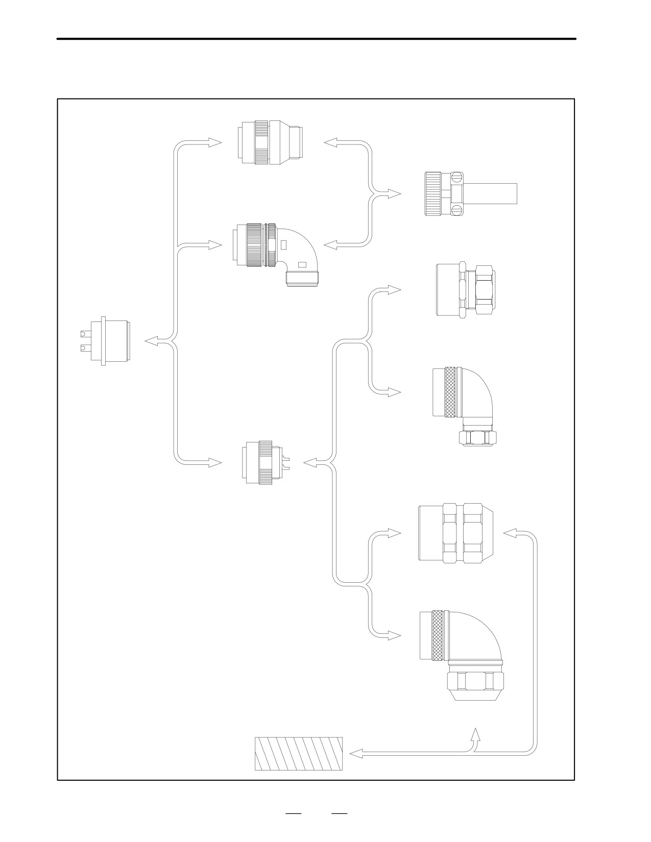
The specifications of each connector are explained based on the examples
shown below.
76
B-65142E/02
DESCRIPTIONS FOR α series
8. CONNECTORS
Example of connector connection
[A]
[C]
Plug connector
(straight type)
[B]
Cable clamp
[E]
Plug connector
(elbow type)
Cable seal adapter
(straight type)
[F]
Receptacle connector
(motor side)
[D]
Cable seal adapter
(90° elbow type)
[G]
Plug connector
(single-unit block type)
Conduit hose seal adapter
(straight type)
[H]
Conduit hose seal adapter
(90° elbow type)
Conduit hose
77
8. CONNECTORS
DESCRIPTIONS FOR α series
B-65142E/02
8.3.1
Specifications of Plug
Connectors on the
Cable Side (Waterproof
TÜV-Approved Type)
Con-
Power cable
Signal cable
Brake/fan cable
nec-
(Common to
(Common to
tor
A3/3000,
A6/2000
A12/2000, A12/3000
A22/3000, A30/2000
all models)
all models)
type
A6/3000
A22/1500, A22/2000
A30/3000, A40/2000
A3/3000HV, A6/3000HV
A30/1200
A40/2000fan
AC3/2000, AC6/2000
A12/3000HV
AL25/3000, AL50/2000
AM3/3000, AM6/3000
A22/3000HV
AM9/3000, AL3/3000
A30/3000HV
AL6/3000, AL9/3000
AC12/2000
AC22/1500
[A]
H/MS3106A18-10S-D-T(10)
JL04V-6A22-22SE-EB
JL04V-6A24-10SE(G)-EB
The IEC34
JL04V-6A10SL-3SE-EB
(Hirose Electric)
(Japan Aviation
(Japan Aviation
standard does
(Japan Aviation
Electronics Industry)
Electronics Industry)
not apply to
Electronics Industry)
signal cable
[B]
H/MS3108B18-10S-D-T(10)
JL04V-8A22-22SE-EB
JL04V-8A24-10SE(G)-EB
connectors.
JL04V-8A10SL-3SE-EB
(Hirose Electric)
(Japan Aviation
(Japan Aviation
(Japan Aviation
Electronics Industry)
Electronics Industry)
Electronics Industry)
[C]
H/MS3057-10A(10)
JL04-2022CK-(14)
JL04-2428CK-(17)
JL04-1012CK-(05)
(Hirose Electric)
(Japan Aviation
(Japan Aviation
(Japan Aviation
Electronics Industry)
Electronics Industry)
Electronics Industry)
[D]
H/MS3106A18-10S-D-T(13)
JL04V-6A22-22SE
JL04V-6A24-10SE(G)
JL04V-6A10SL-3SE
(Hirose Electric)
(Japan Aviation
(Japan Aviation
(Japan Aviation
Electronics Industry)
Electronics Industry)
Electronics Industry)
See the examples of connector connection for [A] to [D].
Note
If connector type [D] is used in conjunction with a cable or
conduit seal adapter to meet the IEC34 standard, contact
an appropriate maker for details.
78
B-65142E/02
DESCRIPTIONS FOR α series
8. CONNECTORS
8.3.2
Specifications of Plug
Connectors on the
Cable Side
(Waterproof Type)
Con-
Power cable
Signal cable
Brake/fan cable
nec-
(Common
to
(Common
to
A3/3000,
A6/2000
A12/2000, A12/3000
A22/3000, A30/2000
tor
all models)
all models)
A6/3000,
A3/3000HV
A22/1500, A22/2000
A30/3000, A40/2000
type
A6/3000HV
A30/1200
A40/2000fan
AC3/2000, AC6/2000
A12/3000HV
AL25/3000,
AM3/3000, AM6/3000
A22/3000HV
AL50/2000
AM9/3000, AL3/3000
A30/3000HV
AL6/3000, AL9/3000
AC12/2000
AC22/1500
[A]
H/MS3106A18-10S(10)
H/MS3106A22-22S(10)
H/MS3106A24-10S(10)
H/MS3106A20-29SW(11)
H/MS3106A10SL-3S(10)
(Hirose Electric)
(Hirose Electric)
(Hirose Electric)
(Hirose Electric)
(Hirose Electric)
JA06A-18-10S-J1-EB
JA06A-22-22S-J1-EB
JA06A-24-10S-J1-EB
JA06A-20-29SW-J1-EB
JA06A-10SL-3S-J1-EB
(Japan Aviation
(Japan Aviation
(Japan Aviation
(Japan Aviation
(Japan Aviation
Electronics Industry)
Electronics Industry)
Electronics Industry)
Electronics Industry)
Electronics Industry)
[B]
H/MS3108B18-10S(10)
H/MS3108B22-22S(10)
H/MS3108B24-10S(10)
H/MS3108B20-29SW(11)
H/MS3108B10SL-3S(10)
(Hirose Electric)
(Hirose Electric)
(Hirose Electric)
(Hirose Electric)
(Hirose Electric)
JA08A-18-10S-J1-EB
JA08A-22-22S-J1-EB
JA08A-24-10S-J1-EB
JA08A-20-29SW-J1-EB
JA08A-10SL-3S-J1-EB
(Japan Aviation
(Japan Aviation
(Japan Aviation
(Japan Aviation
(Japan Aviation
Electronics Industry)
Electronics Industry)
Electronics Industry)
Electronics Industry)
Electronics Industry)
[C]
H/MS3057-10A(10)
H/MS3057-12A(10)
H/MS3057-16A(10)
H/MS3057-12A(10)
H/MS3057-4A(10)
(Hirose Electric)
(Hirose Electric)
(Hirose Electric)
(Hirose Electric)
(Hirose Electric)
JL04-18CK-(13)
JL04-2022CK-(14)
JL04-2428CK-(17)
JL04-2022CK-(14)
JL04-1012CK-(05)
(Japan Aviation
(Japan Aviation
(Japan Aviation
(Japan Aviation
(Japan Aviation
Electronics Industry)
Electronics Industry)
Electronics Industry)
Electronics Industry)
Electronics Industry)
[D]
JA06A-18-10S-J1-(A72)
JA06A-22-22S-J1-(A72
JA06A-24-10S-J1-(A72)
JA06A-20-29SW-J1-(A72)
JA06A-10SL-3S-J1-(A72)
(Japan Aviation
)
(Japan Aviation
(Japan Aviation
(Japan Aviation
Electronics Industry)
(Japan Aviation
Electronics Industry)
Electronics Industry)
Electronics Industry)
H/MS3106A18-10S-(13)
Electronics Industry)
H/MS3106A24-10S(13)
H/MS3106A20-29SW(14)
H/MS3106A10SL-3S(13)
(Hirose Electric)
H/MS3106A22-22S(13)
(Hirose Electric)
(Hirose Electric)
(Hirose Electric)
(Hirose Electric)
[E]
YSO 18-12-14
YSO 22-12-14
YSO 24-15-17
YSO 20-9-11
YSO 10-5-8
(Daiwa Dengyo)
(Daiwa Dengyo)
(Daiwa Dengyo)
(Daiwa Dengyo)
(Daiwa Dengyo)
ACS-12RL-MS18F
ACS-16RL-MS22F
ACS-20RL-MS24F
ACS-12RL-MS20F
(Nippon Flex)
(Nippon Flex)
(Nippon Flex)
(Nippon Flex)
[F]
YLO 18-12-14
YLO 22-12-14
YLO 24-15-17
YLO 20-9-11
YLO 10-5-8
(Daiwa Dengyo)
(Daiwa Dengyo)
(Daiwa Dengyo)
(Daiwa Dengyo)
(Daiwa Dengyo)
ACA-12RL-MS18F
ACA-16RL-MS22F
ACA-20RL-MS24F
ACA-12RL-MS20F
(Nippon Flex)
(Nippon Flex)
(Nippon Flex)
(Nippon Flex)
[G]
BOS 18-15
BOS 22-19
BOS 24-19
BOS 20-15
BOS 10-9
(Daiwa Dengyo)
(Daiwa Dengyo)
(Daiwa Dengyo)
(Daiwa Dengyo)
(Daiwa Dengyo)
RCC-104RL-MS18F
RCC-106RL-MS22F
RCC-106RL-MS24F
RCC-104RL-MS20F
(Nippon Flex)
(Nippon Flex)
(Nippon Flex)
(Nippon Flex)
[H]
BOL 18-15
BOL 22-19
BOL 24-19
BOL 20-15
BOL 10-9
(Daiwa Dengyo)
(Daiwa Dengyo)
(Daiwa Dengyo)
(Daiwa Dengyo)
(Daiwa Dengyo)
RCC-304RL-MS18F
RCC-306RL-MS22F
RCC-306RL-MS24F
RCC-304RL-MS20F
(Nippon Flex)
(Nippon Flex)
(Nippon Flex)
(Nippon Flex)
See the examples of connector connection for [A] to [H].
Combining a plug connector (one-piece block type) and an adapter
(combination of
[D] with
[E] to
[H] in
“Example of connector
connection”) can enhance waterproofness for cables and connector
contacts. (Specification numbers of two manufacturers are listed for
reference.) Of course, conventional waterproof plug connectors may be
used, because they are MS-compatible. This table is only a guideline.
Contact an appropriate maker for details. Do not connect the 0V pulse
corder signal line to the connector shell.
79
8. CONNECTORS
DESCRIPTIONS FOR α series
B-65142E/02
8.3.3
Specifications of Plug
Connectors on the
Cable Side
(Non-waterproof Type)
Con-
Power cable
Signal cable
Brake/fan cable
nec-
(Common to
(Common to
tor
A3/3000,
A6/2000
A12/2000, A12/3000
A22/3000, A30/2000
all models)
all models)
type
A6/3000,
A3/3000HV
A22/1500, A22/2000
A30/3000, A40/2000
A6/3000HV
A30/1200
A40/2000fan
AC3/2000, AC6/2000
A12/3000HV
AL25/3000
AM3/3000, AM6/3000
A22/3000HV
AL50/2000
AM9/3000, AL3/3000
A30/3000HV
AL6/3000, AL9/3000
AC12/2000
AC22/1500
[A]
MS3106B18-10S-(A72)
MS3106B22-22S-(A72)
MS3106B24-10S-(A72)
MS3106B20-29SW-(A72)
MS3106B10SL-3S-(A72)
(Japan Aviation
(Japan Aviation
(Japan Aviation
(Japan Aviation
(Japan Aviation
Electronics Industry)
Electronics Industry)
Electronics Industry)
Electronics Industry)
Electronics Industry)
H/MSA3106A18-10S(10)
H/MSA3106A22-22S(10)
H/MSA3106A24-10S(10)
H/MSA3106A20-29SW(11)
H/MSA3106A10SL-3S(10)
(Hirose Electric)
(Hirose Electric)
(Hirose Electric)
(Hirose Electric)
(Hirose Electric)
[B]
MS3108B18-10S-(A72)
MS3108B22-22S-(A72)
MS3108B24-10S-(A72)
MS3108B20-29SW-(A72)
MS3108B10SL-3S-(A72)
(Japan Aviation
(Japan Aviation
(Japan Aviation
(Japan Aviation
(Japan Aviation
Electronics Industry)
Electronics Industry)
Electronics Industry)
Electronics Industry)
Electronics Industry)
H/MSA3108B18-10S(10)
H/MSA3108B22-22S(10)
H/MSA3108B24-10S(10)
H/MSA3108B20-29SW(11)
H/MSA3108B10SL-3S(10)
(Hirose Electric)
(Hirose Electric)
(Hirose Electric)
(Hirose Electric)
(Hirose Electric)
[C]
MS3057-10A-(A72)
MS3057-12A-(A72)
MS3057-16A-(A72)
MS3057-16A-(A72)
MS3057-4A-(A72)
(Japan Aviation
(Japan Aviation
(Japan Aviation
(Japan Aviation
(Japan Aviation
Electronics Industry)
Electronics Industry)
Electronics Industry)
Electronics Industry)
Electronics Industry)
H/MSA3057-10A(10)
H/MSA3057-12A(10)
H/MSA3057-16A(10)
H/MSA3057-12A(10)
H/MSA3057-4A(10)
(Hirose Electric)
(Hirose Electric)
(Hirose Electric)
(Hirose Electric)
(Hirose Electric)
See the examples of connector connection for [A] to [C].
This table lists only examples. Contact each manufacturer for details.
80
B-65142E/02
DESCRIPTIONS FOR THE α series
9. COOLING FAN FOR MODEL α40
COOLING, FAN, FOR, MODEα,40
9
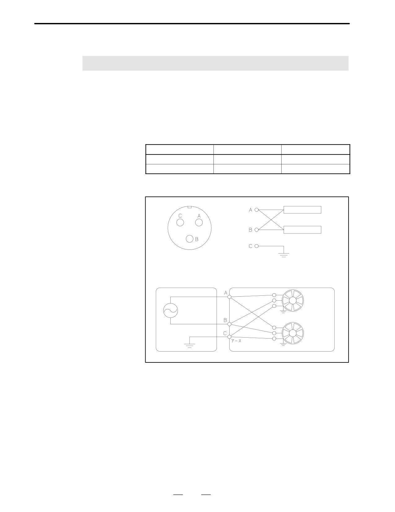
Model α40 can be fitted with an optional cooling fan. The cooling fan
requires a single-phase 200 VAC power supply.
The connection and operating current are given below. Use fuses or a
circuit breaker in the power magnetics cabinet.
Input voltage
Steady-state current
Surge current
200V
Approx. 0.85Arms
Approx. 1.60Arms
230V
Approx. 0.98Arms
Approx. 1.84Arms
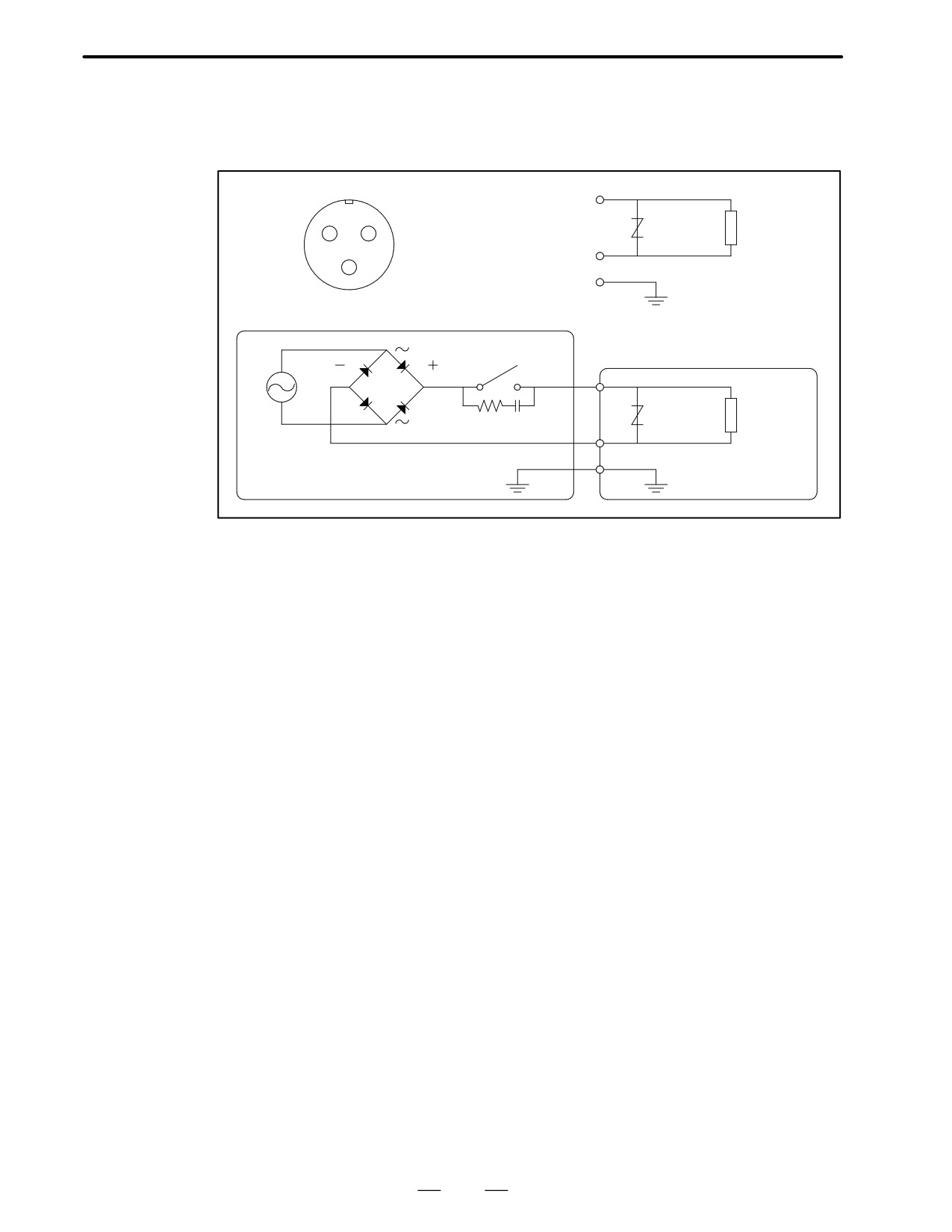
Connection diagram
Fan motor 1
200VAC
Fan motor 2
Grounding plate
Fan motor body
3102A 10SL-3P
Power magnetics
Fan motor unit
Fan
motor 1
Fan
motor 2
81
II. FANUC AC SERVO MOTOR α series
B-65142E/02
FANUC AC SERVO MOTOR α series
1. GENERAL
GENERAL
1
85
1. GENERAL
FANUC AC SERVO MOTOR α series
B-65142E/02
The FANUC AC servo motor α0.5 is a compact servo motor suitable for
1.1
peripheral machine tool equipment. It has the following features:
FEATURES OF
COMPACT-TYPE
α SERVO MOTOR
(α0.5)
Excellent acceleration
A high maximum output torque and intermediate rotor inertia result in
characteristics
excellent acceleration characteristics.
Compact
The use of the latest neodymium ferrite magnet, combined with a
redesigned stator, results in servo motor that is both smaller and lighter
than previous models.
Extended
The use of the latest servo software minimizes the heat generated by
continuous-operation
high-speed rotation, allowing continuous operation over a wide range.
Controllability
The use of the latest servo software maintains controllability even when
a disturbance occurs.
High-performance
The AC servo motor α0.5 is fitted with incremental pulse coder αI8B or
detector
absolute pulse coder αA8B as its standard pulse coder.
Powerful brake
A powerful brake with an increased holding torque is available as an
option. The brake uses an asbestos-free design.
86
B-65142E/02
FANUC AC SERVO MOTOR α series
1. GENERAL
The FANUC AC servo motor α series consists of a range of servo motors
1.2
that are suitable for the feed axes of machine tools. They have the
FEATURES OF
following features:
SERVO MOTOR
α series (α1 to α150)
Excellent acceleration
The rotor inertia has been reduced without sacrificing maximum output
characteristics
torque. As a result, the motors offer excellent acceleration characteristics.
Compact
The use of the latest ferrite magnet, combined with an optimized
mechanical design, reduces both the overall length and weight. The result
is compact, lightweight servo motors.
Excellent waterproofing
The use of waterproof connectors and FANUC’s unique stator seal
provide excellent waterproofing, ensuring that no liquid, such as coolant,
can enter the motor.
Extended
The use of the latest servo software minimizes the heat generated by
continuous-operation
high-speed rotation, allowing continuous operation over a wide range.
Smooth rotation
Further improvements have been made to the unique magnetic pole shape
to minimize torque ripple. The result is extremely smooth rotation.
Controllability
The use of the latest servo software maintains controllability even when
a disturbance occurs.
High-performance
The high-resolution pulse coder model αA64 or αI64 is provided as
detector
standard. This pulse coder allows precise positioning.
Powerful brake
A powerful brake with an increased holding torque is available as an
option. The brake uses an asbestos-free design.
87
2.TYPES OF MOTORS
AND DESIGNATION
FANUC AC SERVO MOTOR α series
B-65142E/02
TYPES, OF, MOTORS, AND, DESIGNATION
2
The types and specifications of α series servo motors are described as
follows.
Model
A06B-01jj-Bl ff
α0.5/3000
jj
13 : Model α0.5/3000
l
0 : Straight shaft (standard)
1 : Straight shaft with the brake (0.65Nm)
ff
78 : With the pulse coder αA8B
80 : With the pulse coder αI8B
Models
A06B-03jj-Bl ff
α1/3000,,α2/2000,
jj
and α2/3000
71 : Model α1/3000
72 : Model α2/2000
73 : Model α2/3000
l
0 : Taper shaft (standard)
1 : Taper shaft with the brake (2Nm)
5 : Straight shaft
6 : Straight shaft with the brake (2Nm)
ff
75 : With the pulse coder αA64
77 : With the pulse coder αI64
84 : With the serial pulse coder A
The standard shafts used for models α1/3000, α2/2000, and α2/3000 are
taper shafts. Use a taper shaft as far as circumstances, such as the delivery
time and maintenance, permit.
88