FANUC I/O Unit–MODEL A CONNECTION AND MAINTENANCE MANUAL MARMGIOMA12801E REV. F (B-61813EN/06) - page 2
1.FANUC I/O Link i AND
B-61813E/06
CONNECTION
FANUC I/O Link
1.2
CONFIGURATION
CNC unit
CNC unit
Group 0
Group 0
JD51A
JD51A
I/O Link
I/O Link i
JD1B
JD1B
JD1A
JD1A
JD2
Group 1
Base
expansion
JD1B
JD3
JD1A
JD2
Group 23
Group 1
JD1B
JD1B
JD1A
JD1A
Group 15
JD1B
JD1A
Maximum number of I/O signals per group
Maximum number of groups per channel
Maximum number of I/O signals per channel
I/O Link i: 512 / 512
I/O Link i (normal mode): 24 groups
I/O Link i (normal mode): 2048 / 2048
I/O Link: 256 / 256
I/O Link: 16 groups
I/O Link: 1024 / 1024
(1) I/O Link i and I/O Link are each comprised of one master and several slaves.
(2) Any slave can be connected to any group. However, different slave types cannot be mixed in one
group.
(3) With I/O Link, up to two units (two bases) can be connected to one group.
(4) With I/O Link i, only one unit (one base) can be connected to one group (no base expansion is
allowed).
- 5 -
1. FANUC I/O Link i AND
FANUC I/O Link
CONNECTION
B-61813E/06
1.3
ALLOCATION OF I/O POINTS
I/O Link i and I/O Link each have the following number of I/O points per channel or group as viewed from
the master.
Number of I/O signals per channel (Xc
Number of I/O signals per group
Communication method
/ Yc)
(Xg / Yg)
I/O Link i
2048 / 2048
512 / 512
I/O Link
1024 / 1024
256 / 256
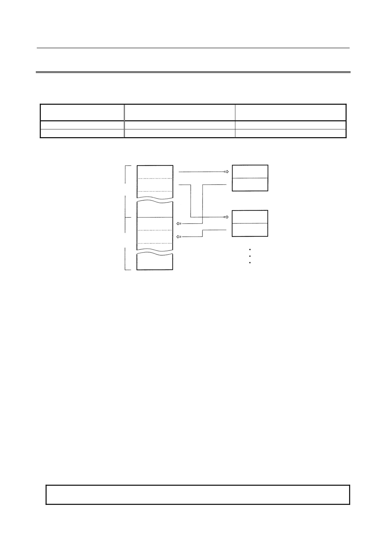
Assigning this I/O to each slave enables periodic I/O data transfer to be performed between the master and
slaves.
Master
Slave #0
Output
Input
Output
Yc points
Slave #1
Output
Input
Input
Xc points
Each slave can occupy as many I/O points as determined for it. For the I/O Link i or I/O Link, the total
number of I/O points occupied by all slaves per channel must meet:
Number of input points ≤ Xc
Number of output points ≤ Yc
Number of actual I/O points may differ from that of the occupied ones.
How to determine the number of I/O points to be allotted to each slave and restrictions for allocation are
shown in the followings.
(For the allocation method for I/O points, refer to the PMC PROGRAMMING MANUAL.)
(1) Sum the numbers of the I/O points for all slaves connected with a single I/O Link i or I/O Link. The
sum must satisfy the following restriction :
Number of input points ≤ Xc (per one channel)
Number of output points ≤ Yc (per one channel)
(2) Number of the occupied I/O points per one group must satisfy the following restriction :
Number of input points ≤ Xg (per one group)
Number of output points ≤ Yg (per one group)
(3) Determine the number of I/O points for the I/O Unit-A using the following.
[Output points]
Sum of the actual output points in a group
Occupied output points
0 to 32
⇒ 32 points
40 to 64
⇒ 64 points
72 to 128
⇒ 128 points
136 to 256
⇒ 256 points
NOTE
Count AOA05E as 8 points AOA12F as 16 points.
- 6 -
1.FANUC I/O Link i AND
B-61813E/06
CONNECTION
FANUC I/O Link
[Input points]
Sum of the actual output points in a group Occupied output points
0 to 32
⇒ 32 points
40 to 64
⇒ 64 points
72 to 128
⇒ 128 points
136 to 256
⇒ 256 points
However, as result of the calculation above, when the number of input points is not larger than that of
the output points in a single group, the number of input points is assumed to be equal to that of the
output points.
Example 1 :
When the following modules are used in the group No. 0.
AOD32C 3
AID32A
5
AOA12F 2
AIA16G
3
[Output points]
32 × 3 + 16 × 2 = 128 ⇒ 128 points
[Input points]
32 × 5 + 16 × 3 = 208 ⇒ 256 points
Example 2:
When the following modules are used in the group No.2
AOD16C 7 AID16C 4
AOA05E 9 AIA16G 3
[Output points]
16 ×7 + 8 ×9 = 184 ⇒ 256 points
[Input points]
16 ×4 + 16×3 = 112 ⇒ 128 points
In this case, as the number of input points is not larger than that of the output points, the number of
input points is assumed to be equal to that of the output points, in other words, 256 points.
NOTE
If no base expansion has been performed, an attempt to allocate I/O points for
base expansion results in an I/O Link error.
- 7 -
2.I/O Unit CONFIGURATION
CONNECTION
B-61813E/06
2 I/O Unit CONFIGURATION
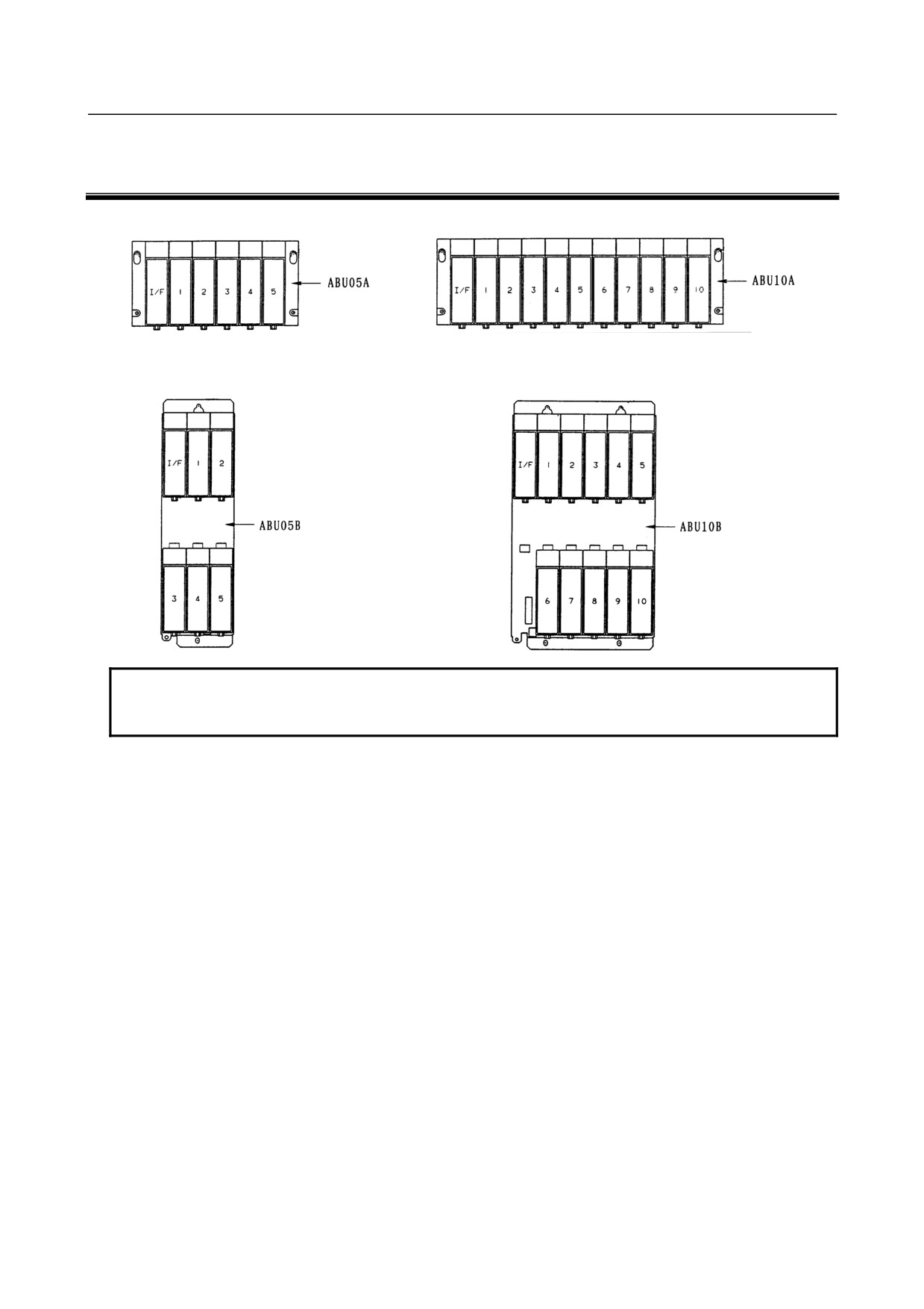
5-slot horizontal base unit (ABU05A)
10-slot horizontal base unit (ABU10A)
5-slot vertical base unit (ABU05B) 10-slot vertical base unit (ABU10B)
NOTE
I/F
: Interface module (AIF01A, AIF01A2, AIF01B, AIF02C, or AIF01D)
1 to 10 : I/O modules
- 8 -
B-61813E/06
CONNECTION
3.INSTALLATION
3 INSTALLATION
3.1
ENVIRONMENT FOR INSTALLATION
3.1.1
Environmental Conditions inside the Cabinet
The peripheral units and the CNC unit have been designed on the assumption that they are housed in closed
cabinets. In this manual "cabinet" refers to the following:
• Cabinet manufactured by the machine tool builder for housing the CNC unit or peripheral units;
• Operation pendant, manufactured by the machine tool builder, for housing the LCD/MDI unit or
operator's panel.
• Equivalent to the above.
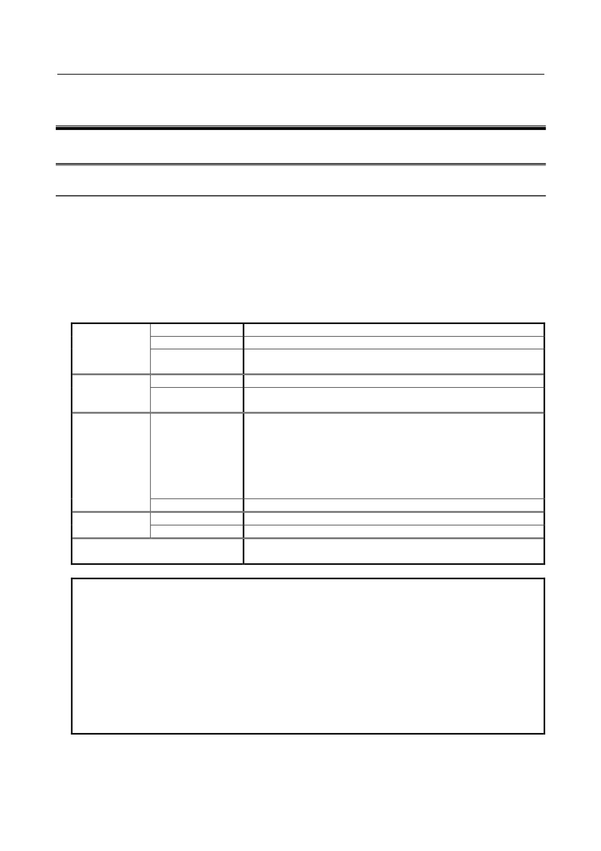
The environmental conditions when installing these cabinets shall conform to the following table. Section
3.2 describes the installation and design conditions of a cabinet satisfying these conditions.
Ambient
Operating
0°C to 55°C
temperature
Storage, Transport
-20°C to 60°C
Temperature
0.3°C/minute or less
change
Humidity
Normal
75%RH or less, no condensation
Short period
95%RH or less, no condensation
(less than 1 month)
Vibration
Operating
0.5G or less
A FANUC evaluation test is performed under the following conditions.
10 to 58Hz
:
0.075mm (amplitude)
58 to 500Hz
:
1G
Vibration directions
: X, Y, and Z directions
Scanning frequency
:
10 cycles
IEC60068-2-6 compliant
Non-operating
1.0G or less
Meters above
Operating
Up to 1000 m (Note)
sea level
Non-operating
Up to 12000 m
Environment
Prevent coolant, lubricant, and chippings from being applied directly to on
the control
NOTE
If the CNC is installed 1000 m or higher above sea level, the allowable upper
ambient temperature of the CNC in the cabinet is changed as follows.
Assume that the allowable upper ambient temperature of the CNC in the cabinet
installed 1000 m or higher above sea level decreases by 1.0°C for every 100 m
rise in altitude.
Example)
The upper allowable ambient temperature of the CNC in the cabinet installed
1750 m above sea level is:
55°C - (1750-1000)/100 × 1.0°C = 47.5°C
Therefore, the allowable ambient temperature range is from 0°C to 47.5°C.
- 9 -
3.INSTALLATION
CONNECTION
B-61813E/06
3.2
DESIGNING CONDITION FOR A CABINET
When designing a cabinet to contain the I/O Unit-A, take the same care as taken for the cabinet containing
the CNC control unit and other units. For details, refer to the CNC CONNECTION MANUAL.
In addition, when mounting the I/O Unit, conform to the followings in view of maintenance, environmental
durability, noise resistance and the like.
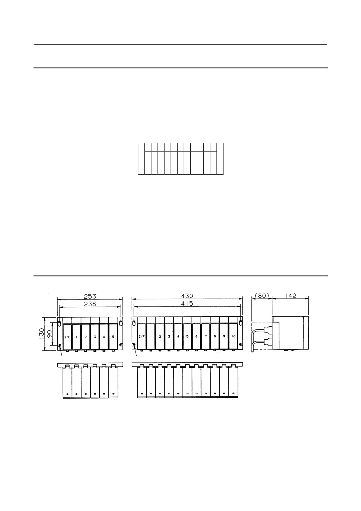
(1) In order to ventilate inside the module well, mount the I/O Unit in the direction shown in the figure
below.
Upside
Downside
(2) Separate each I/O Unit at least 100 mm vertically from the other units so as to ensure effective
ventilation and make it easy to attach/detach wires and modules.
(3) Do not put equipments which generate a large amount of heat under the I/O Unit.
(4) Low-level signals are transferred through the signal cables K1X and K2X. (For these cables, see the
general connection diagram.) Lay out these cables apart from the wires for AC power source and the
I/O wires of the I/O module by 100 mm or more.
(5) Make sure that there is no protruding portion such as a screw on the mounting surface of the I/O Unit.
(6) See Section 3.4, “HEAT VALUE AND WEIGHT OF EACH MODULE” for heat values of I/O Unit.
3.3
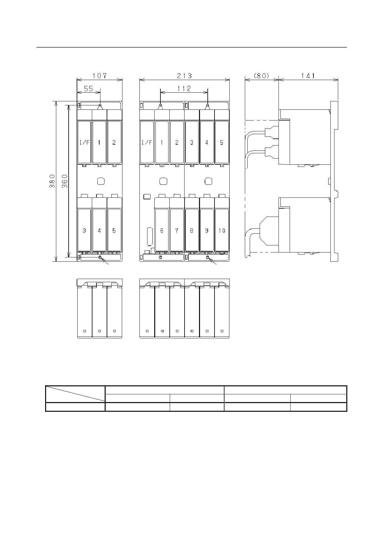
OUTER DIMENSION OF I/O Unit
Horizontal base units (ABU05A and ABU10A)
Hole for an M4 screw (4 places)
Hole for an M4 screw (4 places)
- 10 -
B-61813E/06
CONNECTION
3.INSTALLATION
Vertical base units (ABU05B and ABU10B)
Hole for an M4 screw (2 places)
Hole for an M4 screw (4 places)
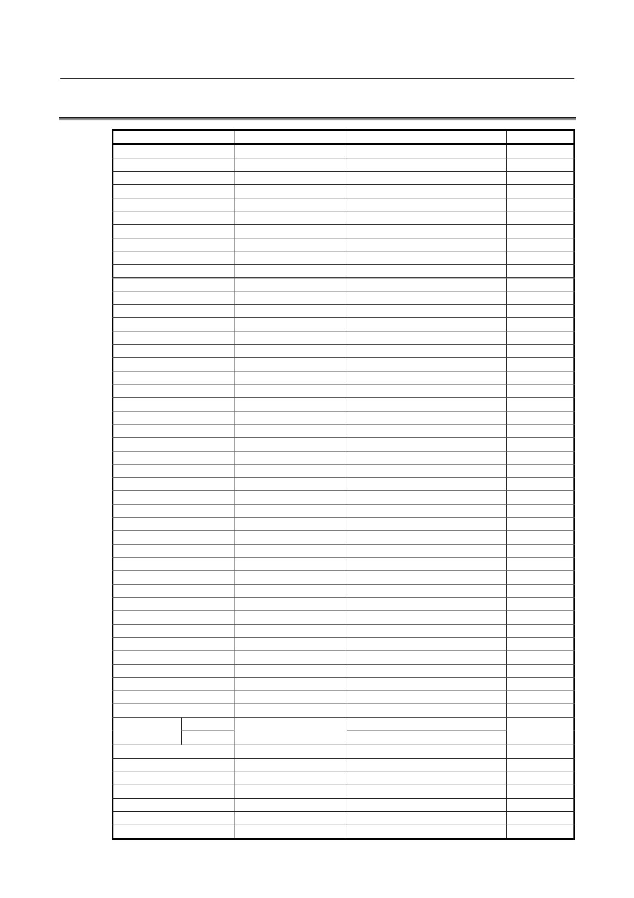
* The ABU05B and ABU10B units that were shipped early on are housed in a metal case.
The distances between mounting holes for the metal case and their size are the same as for the plastic
case used for the current units. However, the width of the metal case differs from that of the plastic
case as listed below.
ABU05B
ABU10B
Plastic case
Metal case
Plastic case
Metal case
Width
107mm
110mm
213mm
217mm
- 11 -
3.INSTALLATION
CONNECTION
B-61813E/06
3.4
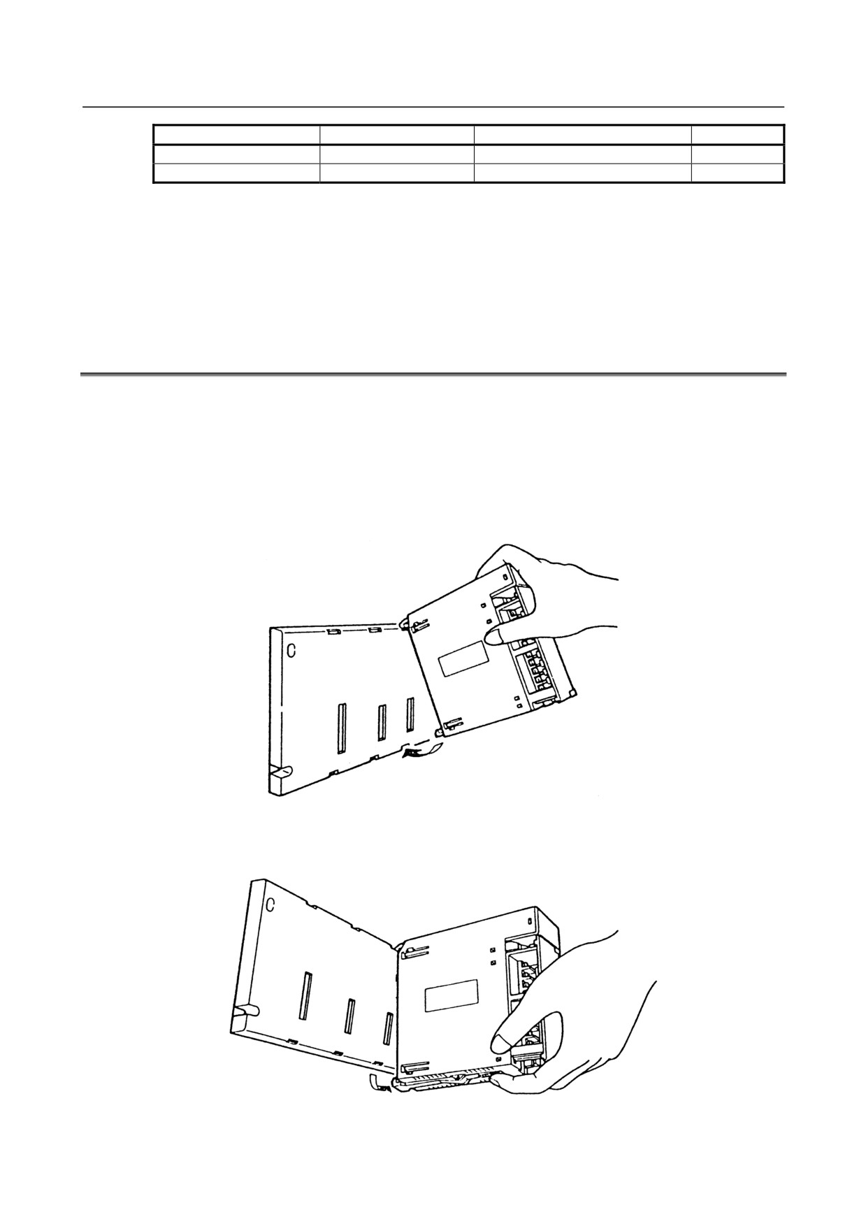
HEAT VALUE AND WEIGHT OF EACH MODULE
Module name
Basic heat value (W)
Heat value per one I/O point (W)
Weight (g)
ABU10A
-
-
600
ABU10B
-
-
740
ABU05A
-
-
350
ABU05B
-
-
380
AIF01A
1.2
-
300
AIF01A2
1.2
-
300
AIF01B
1.2
-
270
AIF02C
1.2
-
300
AIF01D
1.2
-
220
*1
AID32A1
1.2
0.23
250
*2
AID32B1
1.2
0.23
250
AID32H1
1.2
0.23
250
AID16C
0.1
0.21
300
AID16K
0.1
0.21
300
AID16D
0.1
0.21
300
AID16L
0.1
0.21
300
AID16DM
0.1
0.21
290
AID16LM
0.1
0.21
290
*3
AID32E1
0.1
0.23
220
AID32E2
0.1
0.23
220
*4
AID32F1
0.1
0.23
220
AID32F2
0.1
0.23
220
AIA16G
0.1
0.21
300
*5
AOD32A1
0.3
-
220
AOD08C
0.1
0.04+0.4×IL2
380
AOD08D
0.1
0.04+0.6×IL2
380
AOD08DP
0.1
0.04+0.1×IL2
310
AOD16C
0.1
0.04+1.4×IL2
300
AOD16D
0.1
0.04+1.4×IL2
320
AOD16DM
0.1
0.04+0.32×IL2
270
AOD16D2
0.1
0.04+0.1×IL2
320
AOD16D3
0.1
0.04+0.1×IL2
320
AOD16DP
0.1
0.04+1.8×IL2
310
*6
AOD32C1
0.1
0.01+0.8×IL2
220
AOD32C2
0.1
0.01+0.8×IL2
220
*7
AOD32D1
0.1
0.01+0.8×IL2
200
AOD32D2
0.1
0.01+0.8×IL2
200
AOA05E
0.1
0.13+1.5×IL
370
AOA08E
0.1
0.13+1.5×IL
370
AOA12F
0.1
0.11+1.5×IL
320
AOR08G
0.1
0.3+0.1×IL2
300
AOR16G
0.1
0.3+0.1×IL2
350
AOR16H2
0.1
0.3+0.1×IL2
250
Input
0.23
AIO40A
0.2
350
Output
0.01+1.3×IL
AAD04A
3.1
-
350
AAD04B
3.1
-
370
ADA02A
3.1
-
350
ADA02B
3.1
-
350
ACT01A
4.1
-
220
ATI04A
4.0
-
260
ATI04B
4.0
-
260
- 12 -
B-61813E/06
CONNECTION
3.INSTALLATION
Module name
Basic heat value (W)
Heat value per one I/O point (W)
Weight (g)
ATB01A
-
-
100
ATB01B
-
-
120
• Total ‘Heat value per 1 I/O point’ for simultaneous ON points plus ‘Basic heat value’ is the heat value
of the module.
• IL : Load current of output
•
*1 to *7 : "AxD32x" produced to the old specification is equivalent to "AxD32x1" (with additional
"1" at the end) produced to the current specification. (Example: Old specification AID32E
→ AID32E1)
3.5
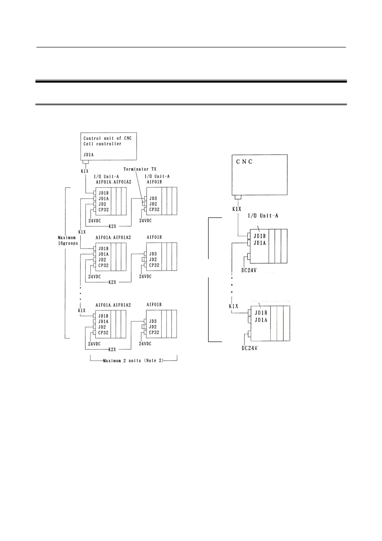
MOUNTING AND DISMOUNTING MODULES
Interface modules and various types of I/O modules can be mounted to and dismounted from the base unit
easily as shown below.
Mounting
Hang the hook at the top of the module on the groove in the upper side of the base unit, and make the
connector of the module engage with that of the base unit. Push the module in the lower groove of the
base unit till the stopper in the lower side of the module stops.
Dismounting
Release the stopper by pushing the lever at the bottom of the module, and then push the module
upwards.
- 13 -
4.CONNECTION
CONNECTION
B-61813E/06
4 CONNECTION
4.1
GENERAL CONNECTION DIAGRAM
Connection diagram of I/O Link
Connection diagram of I/O Link i
JD51A
AIF01D
CPD26
Maximum
24 groups
AIF01D
CPD26
- 14 -
B-61813E/06
CONNECTION
4.CONNECTION
NOTE
1 Number of I/O Units and connecting method are restricted depending on the
allocation of the I/O points. Refer to the section 1.3,"Allocation of I/O points."
2 In case of communication method is I/O Link, one group consists of up to two I/O
units. If the master unit is the F-D Mate, however, one group consists of up to four
I/O units. If the master unit is the F-D Mate, one group can consist of up to four I/O
Units.
3 In case of communication method is I/O Link i, one group consists of up to one I/O
unit only. (No base expansion is allowed.)
4 Cable K1X can be an optical fiber cable by using the optical I/O Link adapter.
See chapter 10.
5 Terminator TX is required for connector JD2 of the AIF01B that is the last unit to
be connected in the group. If no AIF01B is in use, no terminator has to be attached
to the JD2 connector of the AIF01A or AIF01A2.
6 If you want to have the I/O Unit-A support I/O Link i, use the interface module
AIF01D. Doing so makes it possible to the use existing base units and DI/DO
modules.
However, the high-speed counter modules whose unit drawing number is
A03B-0819-C053 or A03B-0807-C053 are dedicated to I/O Link. (See Chapter 8.)
7 Usable power connectors vary depending on which interface module is used.
Before using interface modules, be sure to check their power connectors.
- 15 -
4.CONNECTION
CONNECTION
B-61813E/06
4.2
CONNECTING INPUT POWER SOURCE
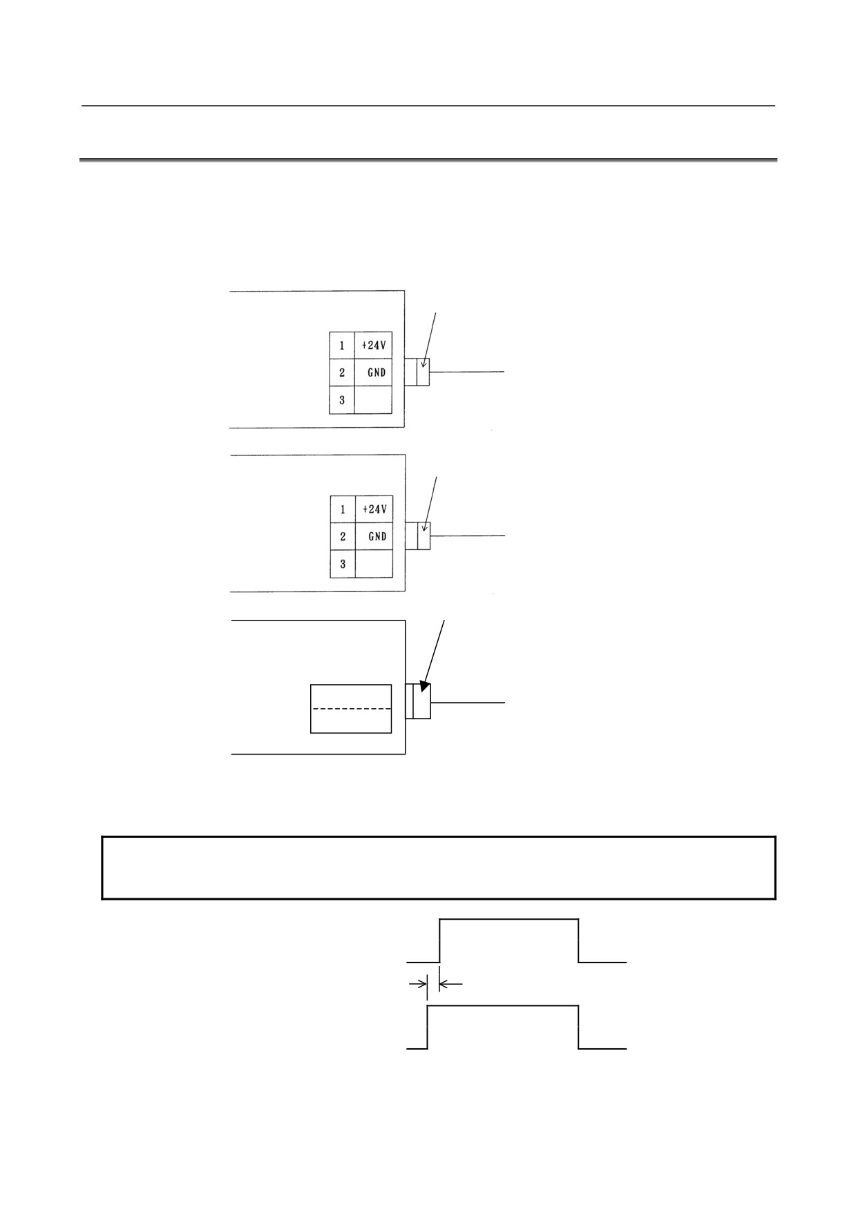
Connect the following power source with the connector CP32, CP1, or CPD26 of the interface module
(AIF01A, AIF01A2, AIF01B, AIF02C, or AIF01D).
• Voltage:
24VDC ±10%
SORIAU JAPAN (manufactured by
• Current: Determine from Table 4.4
former Nippon Burndy)
Tri-pole connector (Brown)
Housing
: SMS3PNS-5
AIF01A / AIF01B / AIF02C
A63L-0001-0202#3LN
CP32
Contact
: RC16M-SCT3
A63L-0001-0226
24VDC
Tyco Electronics
Housing
:
1-178288-3
AIF01A2
Contact
:
1-175218-5
CP1
Housing and contact set
A02B-0120-K324
24VDC
Tyco Electronics
Housing
:
175362-1
Contact
:
1-175218-2
Housing and contact set
AIF01D
A06B-6093-K304
CPD26
Kit of 2 housings and 4 contacts
B A
For input
2
+24V 0V
24VDC
For branch output
1
+24E 0V
NOTE
The contacts in the AIF01D connector kit A06B-6093-K304 are coated with gold.
No tin-coated contact is usable with the AIF01D.
ON
Power for the master
device
OFF
t
ON
Power for the I/O Unit
OFF
t : -500 ms (Turn ON of the power for I/O Unit can be late 500 ms or less.)
- 16 -
B-61813E/06
CONNECTION
4.CONNECTION
NOTE
1 Turn ON the power for the I/O Unit just when or before the power for the CNC or
the cell controller is turned ON. When the CNC or cell controller power is turned
OFF, make sure to turn the power to the I/O Unit OFF as well. Failing to observe
this power ON/OFF sequence may result in an error occurring in the CNC unit or
an I/O unit not being recognized normally.
2 For system safety, configure an external circuit so that the load is supplied with
power only after the I/O unit is supplied with power. Supplying power to the load
before the I/O unit may lead to an accident due to an incorrect output or
malfunction of an output module or the like when the I/O unit is turned on.
3 Always shut off the power to the load before the I/O unit. Otherwise, it is likely that
a machine breakdown or accident may occur.
- 17 -
4.CONNECTION
CONNECTION
B-61813E/06
4.3
GROUNDING
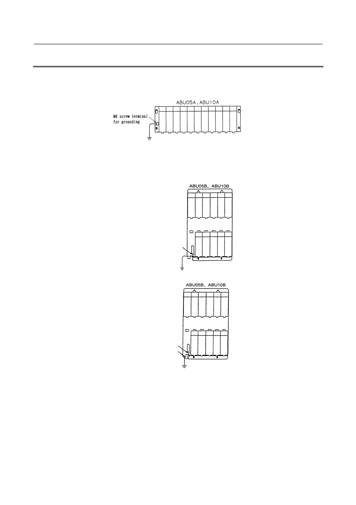
Connect the grounding terminal of the base unit (ABU05A, ABU05B, ABU10A, or ABU10B) to ground.
(1) Horizontal type base unit
Use a wire of 2 mm2 or more for grounding.
(2) Vertical type base unit
(a) For plastic case
M3 screw terminal for
grounding terminal
(b) For metal case (early shipment)
M3 screw terminal for
grounding terminal
M4 hole for grounding
- 18 -
B-61813E/06
CONNECTION
4.CONNECTION
NOTE
1 Connect the screw terminal for grounding terminal to the grounding hole portion.
2 Use dedicated grounds as much as possible.
Observe your national grounding standards (protective grounding class C or
stricter). If possible, use a dedicated ground to isolate it from that for other units.
If no dedicated ground is available for the unit, it can share a common ground with
other units.
However, absolutely avoid having the unit share a ground with high-power
equipment such as motors and inverters. Ground them at their respective
grounds so that they will not mutually affect others.
Do not ground the unit at a point where many units are grounded in order to
prevent electrical shocks.
3 Use single-point grounding so that no noise will be induced on the grounding
line between units. In some cases, however, both ends grounding or both ends
opening may be more effective depending on the environment where the unit is
used. Select one of the grounding types, whichever is appropriate, depending on
what the ambient noise is like.
- 19 -
4.CONNECTION
CONNECTION
B-61813E/06
4.4
REQUIRED CURRENT
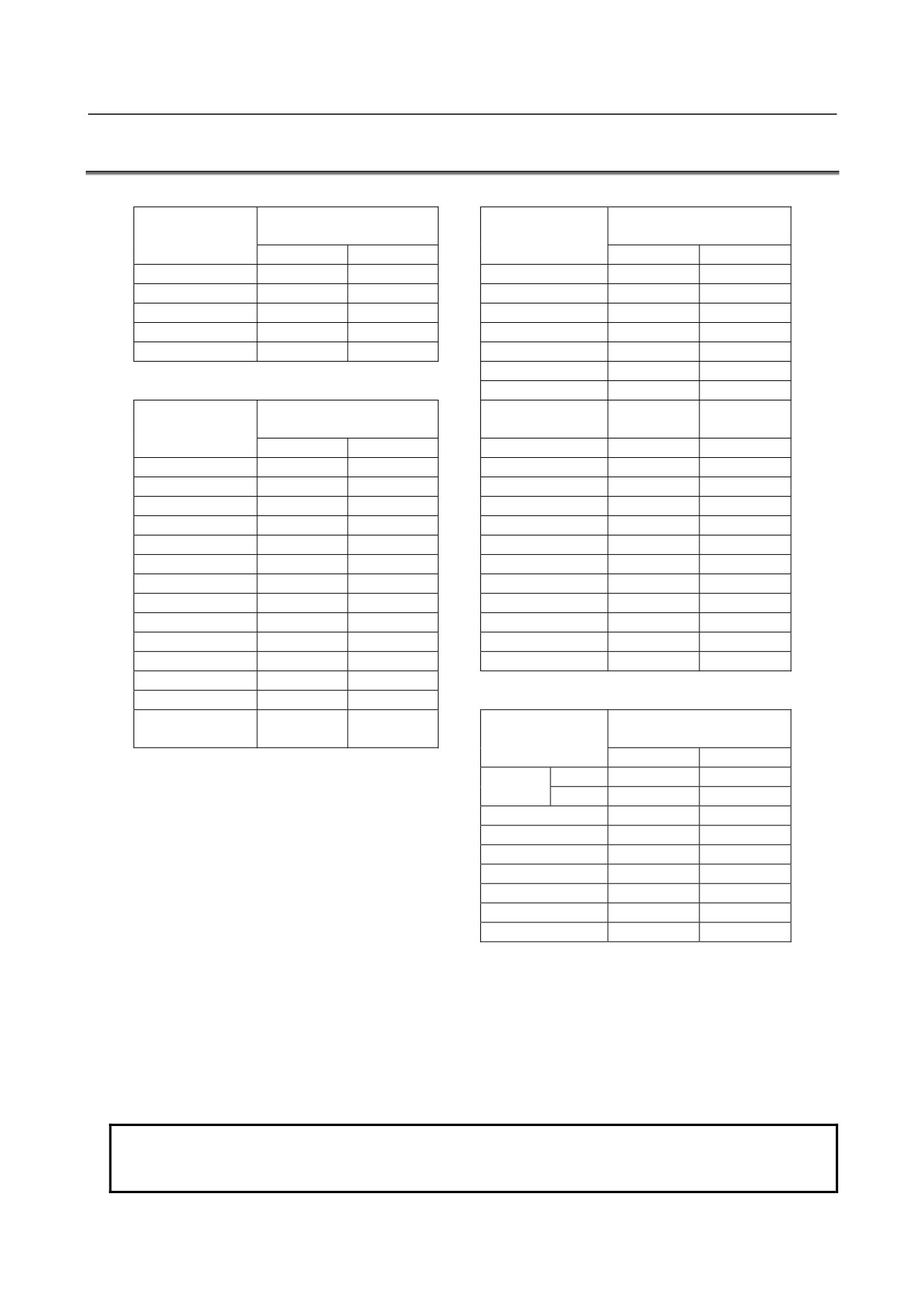
Interface module
Output module
Required current (mA)
Required current (mA)
Module name
of+24V
Module name
of+24V
A
B
A
B
AIF01A
50
AOD32A1
14
AIF01A2
50
AOD08C
5+2×n
AIF01B
50
AOD08D
5+2×n
AIF02C
50
AOD08DP
5+2×n
AIF01D
50
AOD16C
5+2×n
AOD16D
5+2×n
Input module
AOD16DM
5+2×n
Required current (mA)
AOD16D2
5+2×n
Module name
of+24V
A
B
AOD16D3
5+2×n
AID32A1
20+0.5×n
30+7.5×n
AOD16DP
5+2×n
AID32B1
20+0.5×n
30+7.5×n
AOD32C1
5+0.5×n
AID32H1
20+0.5×n
30+7.5×n
AOD32C2
5+0.5×n
AID16C
5
AOD32D1
5+0.5×n
AID16K
5
AOD32D2
5+0.5×n
AID16D
5
AOA05E
5+5.5×n
AID16L
5
AOA08E
5+5.5×n
AID16DM
5
AOA12F
5+4.5×n
AID16LM
5
AOR08G
5
10×n
AID32E1
5
AOR16G
5
10×n
AID32E2
5
AOR16H2
5
10×n
AID32F1
5
AID32F2
5
Special module
Required current (mA)
AIA16G
5+1.5×n
Module name
of+24V
A
B
Input
20+0.5×n
30+7.5×n
AIO40A
Output
5+0.5×n
AAD04A
5
130
AAD04B
5
130
ADA02A
6
120
ADA02B
6
130
ACT01A
170+0.3×α
ATI04A
62.5
100
ATI04B
62.5
100
n: Number of the input and output points (for each module) which turn ON simultaneously
α:
+5-V current (mA) output to the outside
•
Add the sums of the columns A and B for the modules to be used. The sum is the required
current.(Unit: mA)
•
For each base unit, keep the sum of column A and the sum of column B to within 500 mA and 1,500
mA, respectively.
NOTE
Do not use the unit in such a way that the total of the maximum power
consumptions of its modules may exceed the capacity of the power source for it.
- 20 -
B-61813E/06
CONNECTION
4.CONNECTION
4.5
INTERFACE MODULE (AIF01A, AIF01A2, AIF01B)
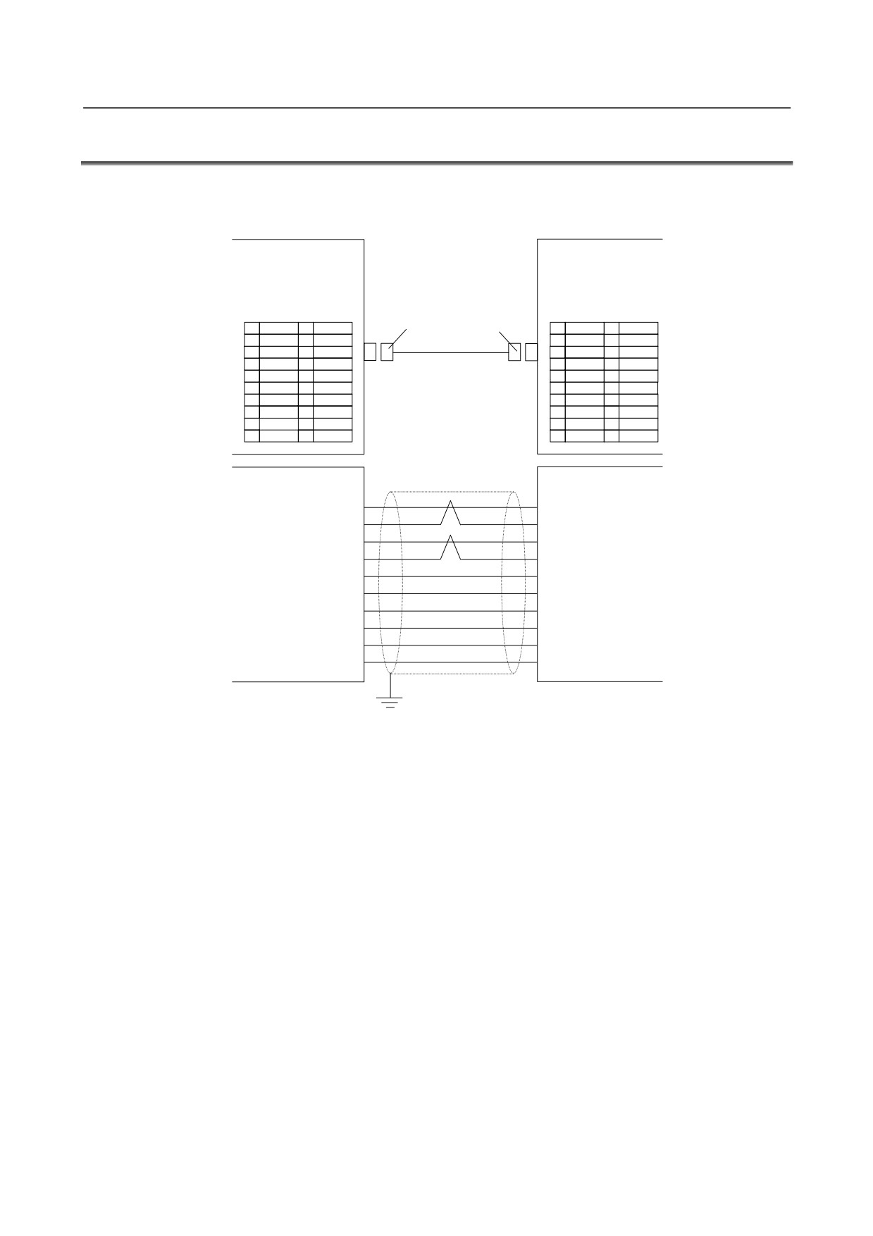
Details of the cables K1X, K2X and the terminator shown in the general connection diagram are as follows.
(1) Cable K1X
CNC unit
or
AIF01A, AIF01A2,
AIF01A, AIF01A2
JD51A, JD44A, JD1A
Connector HONDA TSUSHIN
JD1B
1
SIN
11
0V
PCR-E20FS
1
SIN
11
0V
2
*SIN
12
0V
2
*SIN
12
0V
3
SOUT
13
0V
3
SOUT
13
0V
4
*SOUT14
0V
4
*SOUT14
0V
5
15
0V
5
15
0V
6
16
0V
6
16
0V
7
17
7
17
8
18
8
18
9
19
9
19
10
20
10
20
JD1A
JD1B
SIN
(1)
(3)
SOUT
*SIN
(2)
(4)
*SOUT
SOUT
(3)
(1)
SIN
*SOUT
(4)
(2)
*SIN
0V
(11)
(11)
0V
0V
(12)
(12)
0V
0V
(13)
(13)
0V
0V
(14)
(14)
0V
0V
(15)
(15)
0V
0V
(16)
(16)
0V
•
Make sure to use twisted pair wires for signal SIN and *SIN, and signals SOUT and *SOUT.
•
Recommended cable material: A66L-0001-0284#10P (twisted pair/shielded)
•
Shielding wires should be connected with the grounding plate of the cabinet at the JD1A side
using a cable clamp. (Refer to the CONNECTION MANUAL for the CNC unit.)
•
Maximum cable length: 10 m (15 m if used to connect I/O devices within the same cabinet)
•
In the following cases, make sure to use an optical I/O Link adapter and an optical fiber
cable.(See Chapter 10)
-
When the cable is more than 10 meters long.
-
When the cable runs between different cabinets and there is no appropriate ground wire
between the cabinets.
-
When there is concern that the cable is influenced by strong noise.
•
When an optical I/O Link adapter is used: Cable to be used between the interface module
(AIF01A) and the optical adapter is dissimilar to this cable. (See Chapter 10.)
- 21 -
4.CONNECTION
CONNECTION
B-61813E/06
NOTE
1 The AIF01A and AIF01A2 are dedicated to I/O Link. They cannot be used with I/O
Link i.
2 The +5V pin enclosed in () is intended to supply power to an optical adapter for
connection through an optical fiber cable. When using no optical adapter, do not
connect the +5V pin.
3 The pins enclosed in [ ] are used by the JD44A or JD51A for channel 2 or 3
connection. Do not connect anything to them.
4 Do not connect anything to pins to which no signal is assigned.
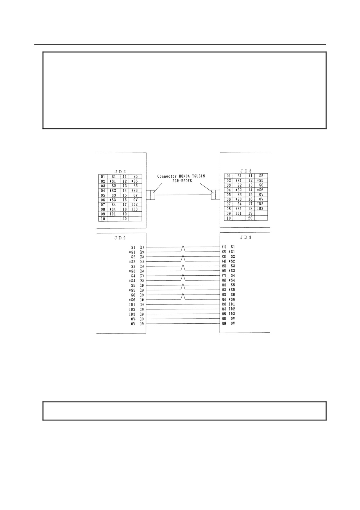
(2) Cable K2X
AIF01A, AIF01A2, or
AIF01B
AIF01B
•
Connect the signals with a same name.
•
Make sure to use twisted pair wires for the following signals:
S1 and * S1, S2 and *S2, S3 and *S3
S4 and * S4, S5 and *S5, S6 and *S6
•
Do not connect the pins No.10, No.19 and No.20 as they are used internally.
•
Recommended cable material: A66L-0001-0284#10P (twisted pair/shielded)
•
Maximum cable length: 2m
NOTE
The AIF01B is dedicated to I/O Link. It cannot be used with I/O Link i.
- 22 -
B-61813E/06
CONNECTION
4.CONNECTION
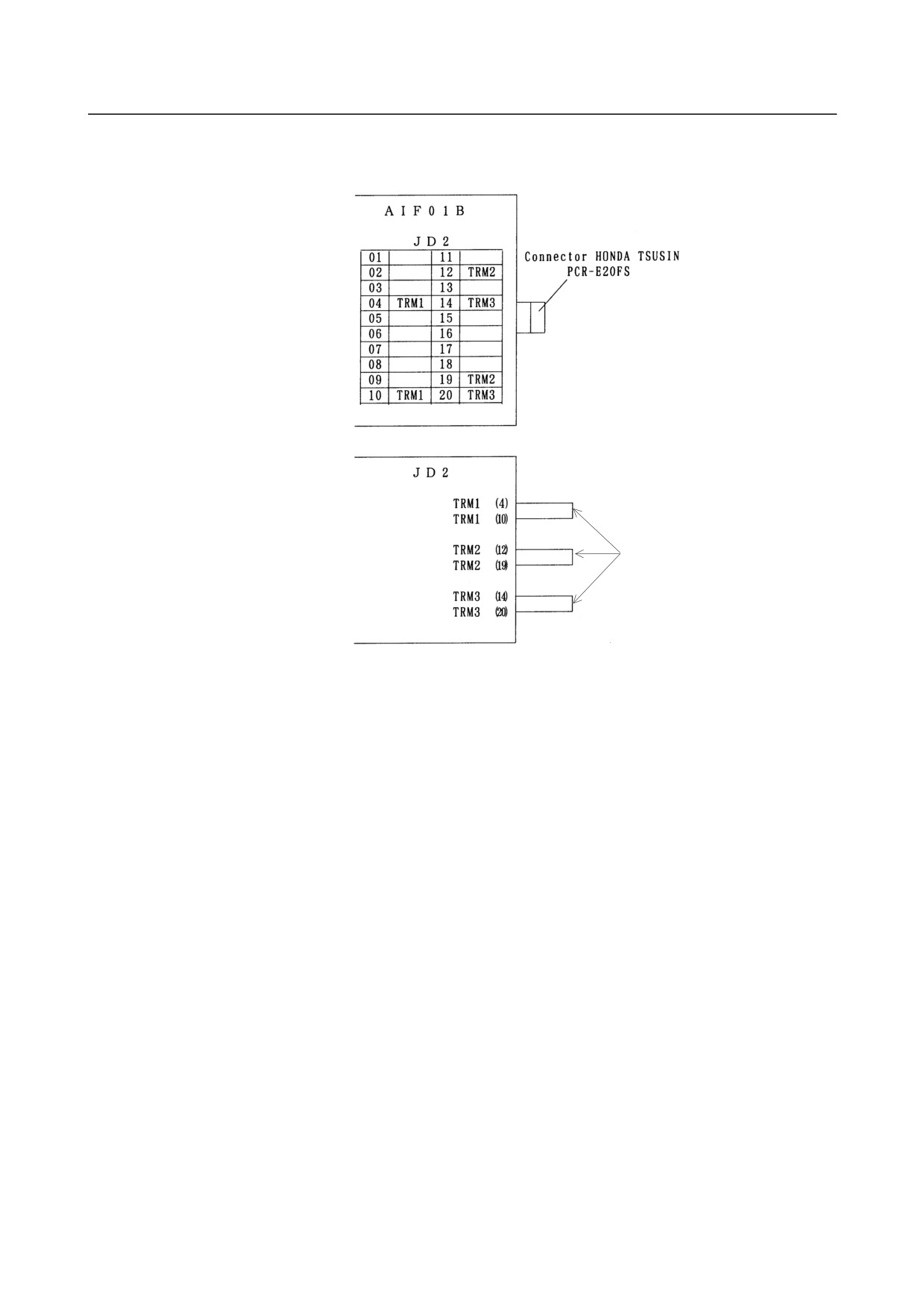
(3) Terminator TX
Ordering information : A03B-0807-K806
Short-circuit
•
If no AIF01B is in use, the TX terminator does not have to be attached to the JD2 connector of the
AIF01A or AIF01A2.
•
If at least one AIF01B is in use, attach the terminator to the JD2 connector of the last AIF01B in
the same group.
•
Short-circuit the TRM1s, the TRM2s and the TRM3s one another respectively in a manner that a
TRM1 is with another TRM1 and so on.
- 23 -
4.CONNECTION
CONNECTION
B-61813E/06
4.6
INTERFACE MODULE (AIF02C) CONNECTION
4.6.1
Overview
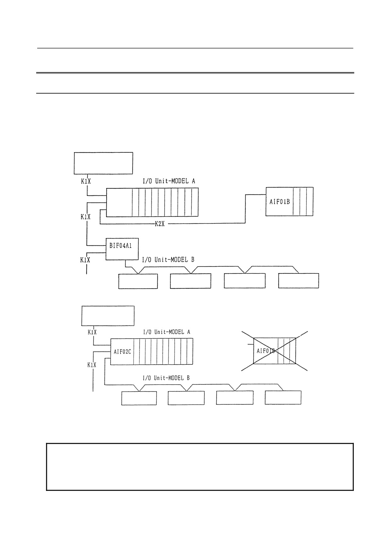
One interface module (AIF02C) can control communication with both I/O Unit-A and Unit-B, when it is
connected to the I/O Link.
The following examples show a configuration in which two conventional separate interface modules, I/O
Unit-A and I/O Unit-B, are used and a configuration in which the AIF02C is used.
(1) Configuration example in which separate interface modules are used
CNC cell controller
AIF01A
AIF01A2
Group #0
Base expansion
Group #1
(Note 2)
To the next group
DI/DO unit
DI/DO unit
DI/DO unit
DI/DO unit
(2) Configuration example in which AIF02C is used
CNC cell controller
(NOTE 1)
Group #0
Base expansion
(Note 2)
Group #1
To the next group
DI/DO unit
DI/DO unit
DI/DO unit
DI/DO unit
In this way, using the AIF02C eliminates the necessity for the interface unit (BIF04A1) for I/O Unit-B,
which has conventionally been used separately; this configuration is suitable for a small I/O Unit-B system.
Note the following points.
NOTE
1 The AIF02C is dedicated to I/O Link. It cannot be used with I/O Link i.
2 The AIF02C cannot be used for base expansion.
3 The BIF04A1 can branch to a maximum of eight communication lines.
The AIF02C can branch only to a maximum of two distributed link cables.
- 24 -
B-61813E/06
CONNECTION
4.CONNECTION
4.6.2
Connection
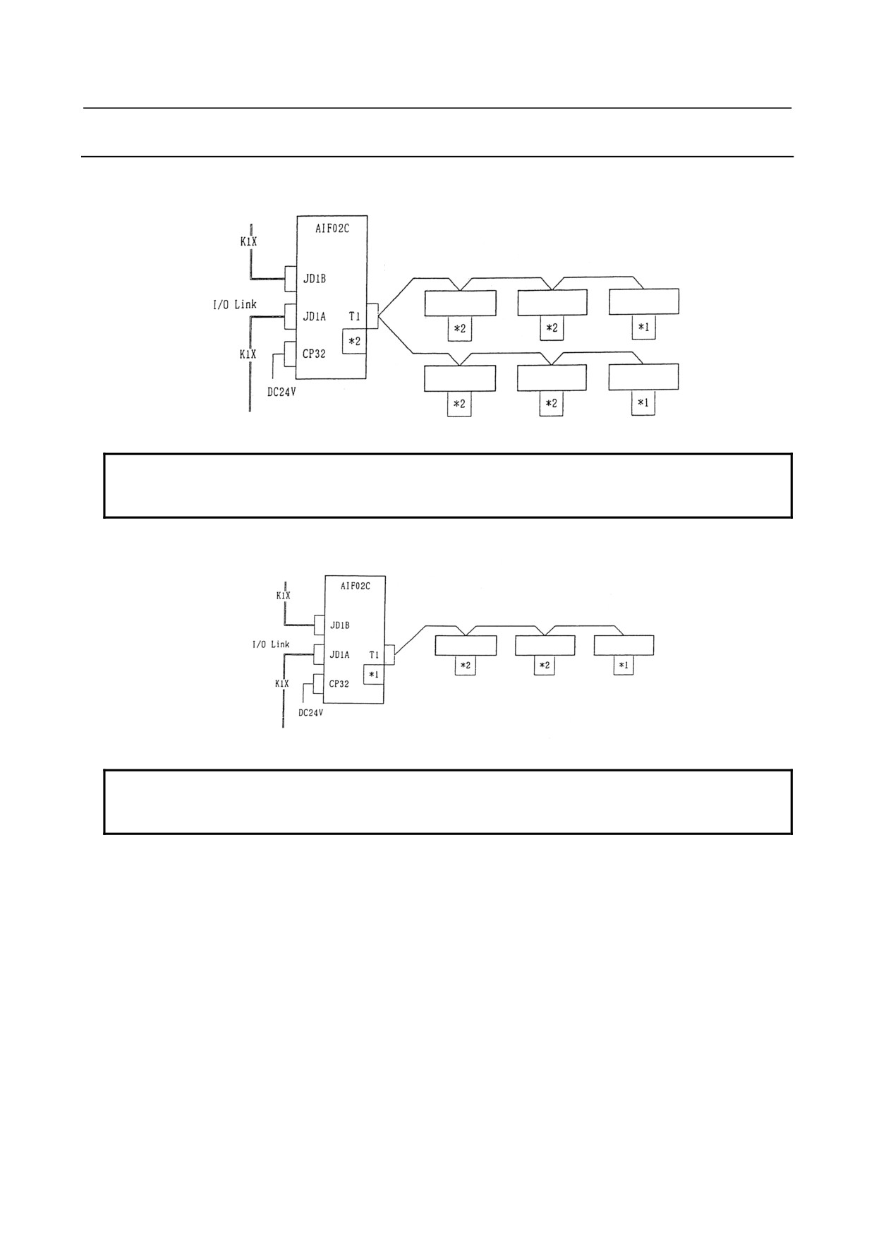
(1) Connection diagram
[a] Configuration with two distributed link cables (note the setting of the terminating resistor.)
(From group n-1)
Groups n
and n+1
Distributed link
DI/DO unit
DI/DO unit
DI/DO unit
DI/DO unit
DI/DO unit
DI/DO unit
(To group n+2)
NOTE
*1 Set the terminating resistor DIP switch to ON.
*2 Set the terminating resistor DIP switch to OFF.
[b] Connection with one distributed link cable (note the setting of the terminating resistor.)
(From group n-1)
Groups n
and n+1
Distributed link
DI/DO unit
DI/DO unit
DI/DO unit
(To group n+2)
NOTE
*1 Set the terminating resistor DIP switch to ON.
*2 Set the terminating resistor DIP switch to OFF.
(2) Connection with the I/O Link
The AIF02C occupies two groups on the I/O Link.
When groups #n and #n+1 are used, for example, the smaller-numbered group, #n, is assigned to the
I/O Unit-A, and the larger-numbered group, #n+1, is assigned to the I/O Unit-B.
[a] Connection of the I/O Link cable
Connect the I/O Link cable from the previous group to JD1B. Connect JD1A to the I/O Link
cable leading to the next group. Use the K1X I/O Link signal cable, the same I/O Link signal
cable type as that for the AIF01A.
[b] Number of occupied I/O points on the I/O Link
The nominal number of occupied I/O points may differ from the actual number of I/O points.
For the details of the number of I/O points occupied by the I/O Unit-B, refer to Section, "Number of
points occupied on the interface unit I/O Link," of the FANUC I/O Unit-B MODEL Connection
Manual (B-62163E).
(3) Connection with the distributed link (I/O Unit-B)
[a] Number of distributed communication lines
- 25 -
4.CONNECTION
CONNECTION
B-61813E/06
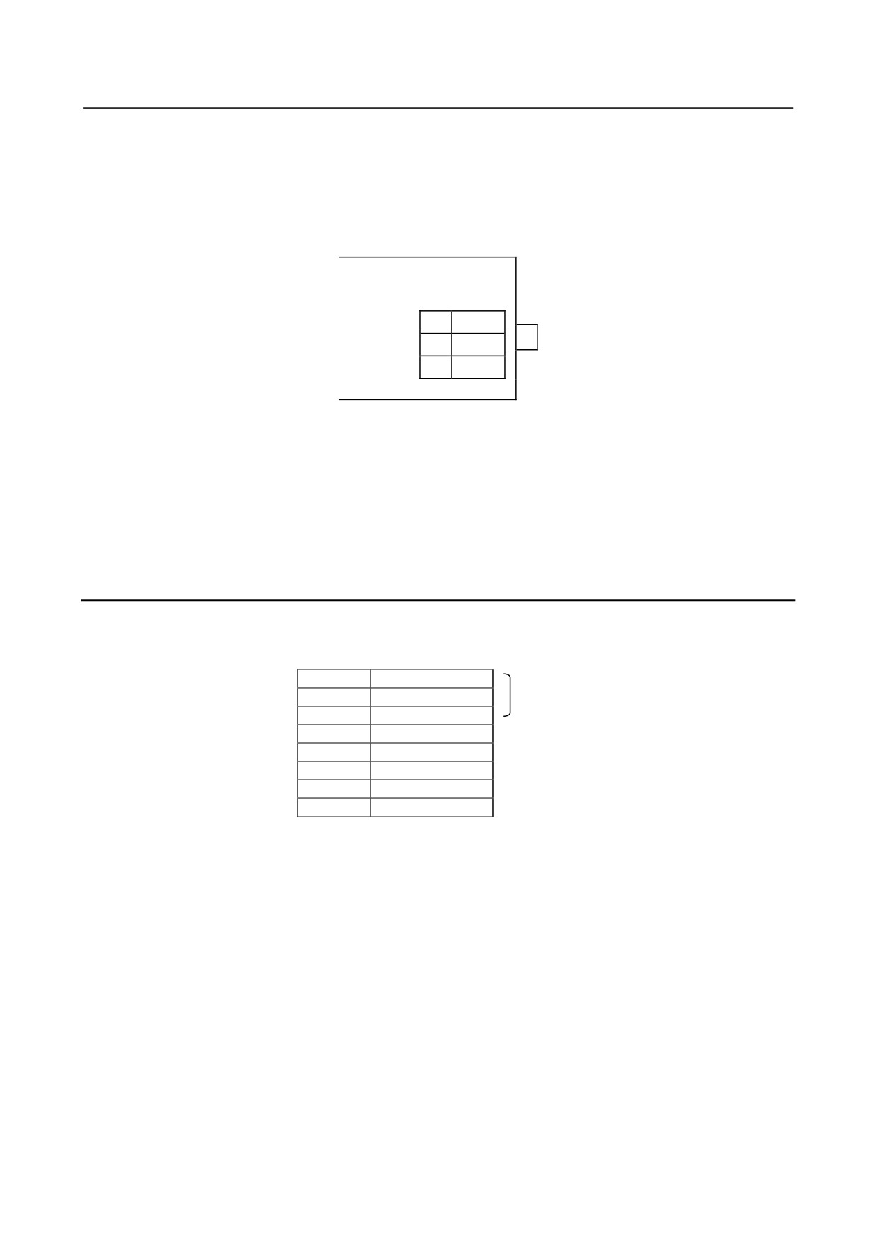
"T1" can connect to two communication lines (twisted-pair wires).
So, it is possible to branch to up to two lines.
To branch to more lines, you should use the I/O Unit-B interface unit (BIF04A1), which enables
branching to up to eight communication lines.
[b] Terminal board "T1," used for connection with the distributed link cable
The distributed link cable is connected to "T1."
AIF02C
T1
1
S+
2
S-
3
FG
<1> Use twisted-pair wires as the distributed link cable.
<2> The distributed link cable is polarity-sensitive. Match the signal polarity of the AIF02C with
that of the basic unit.
<3> The terminal board has M3 screws with a terminal cover.
Refer to Section, "Connecting a Distributed Link," and Subsection, "Connecting the communications
cable," of the FANUC I/O Unit-MODEL B Connection Manual (B-62163E) for details.
4.6.3
Setting with the DIP Switch
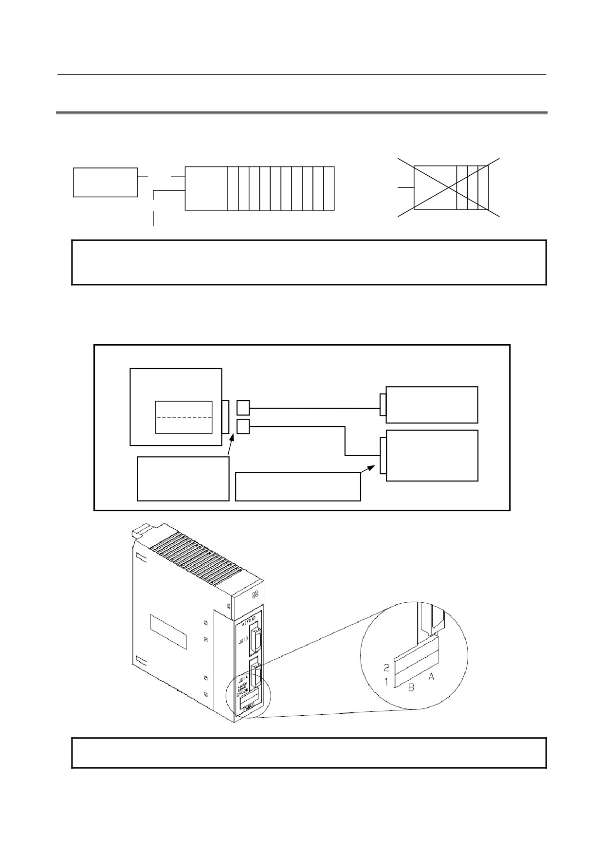
In the AIF02C, distributed link settings can be made with the DIP switch on the back of the module.
The settings and corresponding signals are shown below.
1
2
Unused
3
4
EDSP
5
Q
6
H
7
URDY
8
R
(1) EDSP (error display method selection)
Normally, set EDSP to the ON position.
(2) Q and H (communication speed setting)
Normally, set both Q and H to the OFF positions.
(3) URDY (setting of the power on/off information for the unit)
Normally, set URDY to the OFF position.
(4) R (terminating resistor setting)
The ON position means that a terminating resistor must be installed. The OFF position means that no
terminating resistor need be installed.
When only one communication cable is connected to the AIF02C, terminate it and the basic unit at the
end of the communication cable with a resistor.
When two communication cables are connected to the AIF02C, terminate the basic unit connected to
the end of each communication cable with a resistor. Do not connect a terminating resistor to the
AIF02C. (Refer to Subsection 4.6.2, "Connection.")
Refer to Subsection, "DIP switch setting," of the FANUC I/O Unit-MODEL B CONNECTION MANUAL
(B-62163E).
- 26 -
B-61813E/06
CONNECTION
4.CONNECTION
4.7
INTERFACE MODULE (AIF01D) CONNECTION
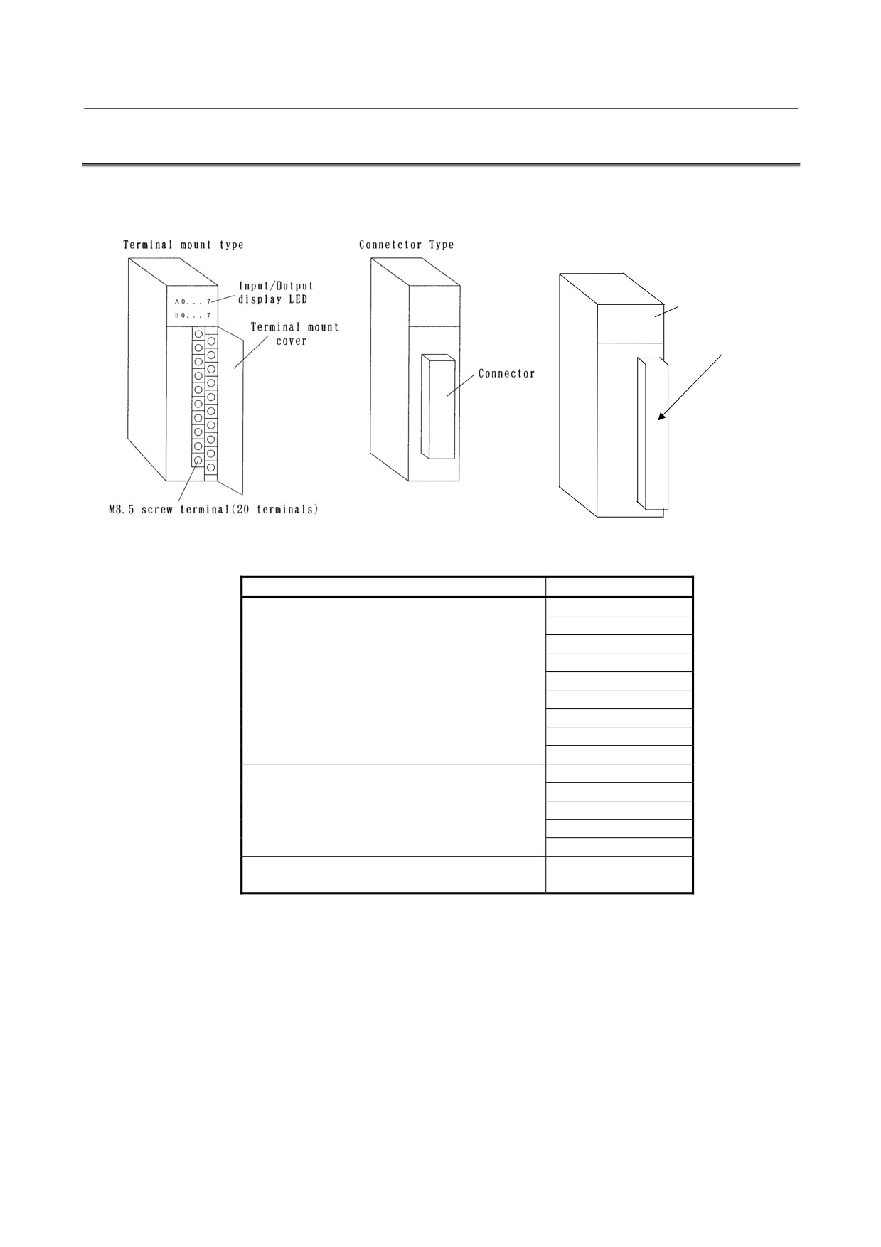
Connecting the interface module (AIF01D) to I/O Link i enables communication control to be performed
for the I/O Unit-A. Shown below is an example configuration in which the AIF01D is in use.
I/O Unit-MODEL A
Note2
K1X
CNC unit
AIF01D
AIF01B
K1X
Base expansion
NOTE
1 The AIF01D is dedicated to I/O Link i. It cannot be used with I/O Link.
2 With the AIF01D, no base expansion is allowed.
A voltage of 24 VDC input to the CPD26 (2A, 2B) can be output from the CPD26 (1A, 1B) for branching
purposes. The CPD26 connection is shown below. The external 24 VDC power supply must supply the
current capacity consumed by the I/O Unit-A and that used via the CPD26 (1A, 1B) to the CPD26 (2A, 2B).
AIF01D
CPD26
B A
External 24VDC
2
+24V 0V
1
+24E 0V
Connected for
branching purposes.
External device
Tyco Electronics
175362-1 (housing)
Select a connector that matches
1-175218-2 (contact)
the pins of the external unit.
NOTE
The CPD26 (1A, 1B) can supply up to 2 ADC.
- 27 -
4.CONNECTION
CONNECTION
B-61813E/06
4.8
CONNECTING WITH I/O MODULES
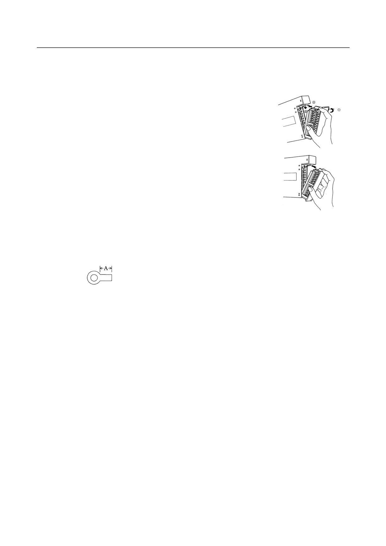
From the point of view of an external connecting method, there are two types of I/O modules such as one
with a terminal block and one with a connector.
Terminal block manufactured by
Weidmüller (used in the AOD16D3)
Input/output
display LED
A 0 . . .
7
Specification of the terminal
B 0 . . .
7
block on the module
BL3.5//24/90F
The following three different connectors can be used on the connector-type module.
Specification of the connector on the module
Module name
AID32A1
AID32B1
AID32H1
Manufactured by HONDA TSUSHIN
AID32E1
MR-50RMA
AID32F1
(male)
AOD32A1
AOD32C1
AOD32D1
AIO40A
AID32E2
AID32F2
Manufactured by HIROSE ELECTRIC
AOD32C2
HIF3BB-50PA-2.54DS
AOD32D2
AOR16H2
Manufactured by HIROSE ELECTRIC
AOD16D2
HIF4-40P-3.18DS
- 28 -
B-61813E/06
CONNECTION
4.CONNECTION
(1)
Connect with each module following the connection diagrams of Sections 4.2 and 5.3.
(2)
The terminal block is a removable type.
[Dismounting the terminal block]
<1> Open the cover of the terminal block.
<2> Push up the latch at the top of the terminal block.
<3> Drag out the tab at the top of the terminal block and pull it out. The
terminal block will be removed from the module.
[Mounting the terminal block]
<1> Insert the protruding portion at the bottom of the terminal block in
the groove of the module side.
<2> Push the terminal block using the engaging point of the protruding
portion and the groove as an axis and mount it in the module
firmly.
<3> Open the cover of the terminal block and check to make sure the
latch at the top of the terminal block is firmly set.
(3)
Cautionary points when wiring terminal block type
•
Wiring material : AWG22 to 18 (0.3 to 0.75 mm2)
It is recommended to use as thin a wire as possible provided that the wire diameter matches the
intended use.
•
Crimp style terminal : M3.5
Crimp style terminal with no insulation sleeve and a short distance "A", as illustrated in the
drawing below, is recommended.
DAIDO SOLDERLESS TERMINAL
1.25-S3.5
NICHIFU
1.25-3.5S etc.
•
Mark tube : Use a short mark tube as possible and cover crimped part with the mark tube.
•
Recommended tightening torque : 1 to 1.4 N⋅m
(4)
Wiring to the terminal block manufactured by Weidmüller
•
Wire with a cross section of 0.08 to 1.5 mm2 (VDE)/AWG28 to AWG14 (UL/CSA)
•
Recommended tightening torque: 0.8 N⋅m
•
Size conformable when a ferrule (rod terminal) is used: 0.5 to 1.5 mm2
Peeling length: 6 mm
- 29 -
5. DIGITAL INPUT/OUTPUT
MODULES
CONNECTION
B-61813E/06
5 DIGITAL INPUT/OUTPUT MODULES
5.1
LIST OF MODULES
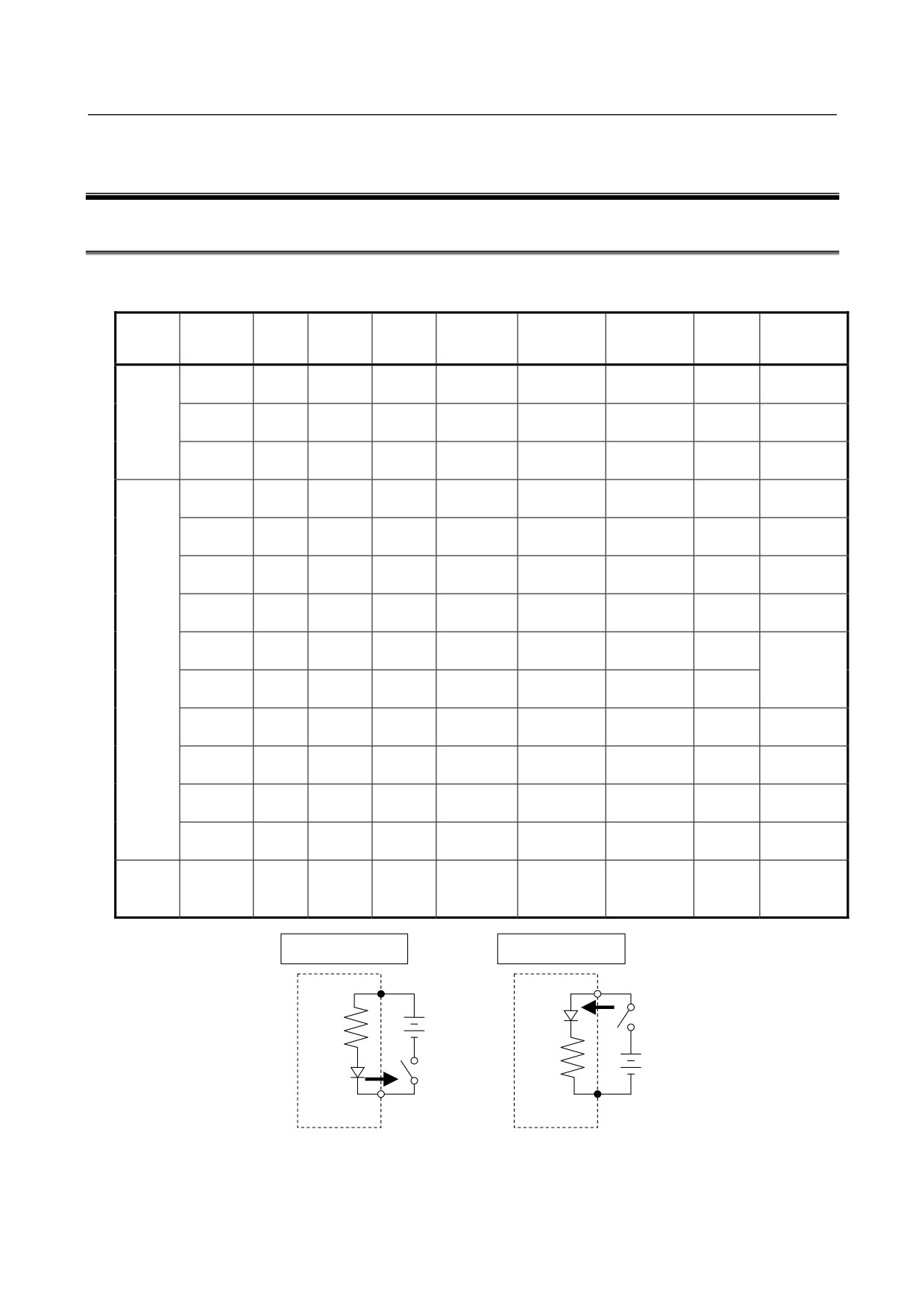
(1) Digital input modules
Response
External
Input
Module
Rated
Rated
Polarity
LED
Additional
time
Points
connection
type
name
voltage
current
(Note 1)
display
function
(maximum)
(Note 2)
Not
AID32A1
24VDC
7.5mA
Both
20msec
32
Connector A
Non-
provided
insulation
Not
AID32B1
24VDC
7.5mA
Both
2msec
32
Connector A
type DC
provided
input
2msec
8
Not
AID32H1
24VDC
7.5mA
Both
Connector A
20msec
24
provided
Terminal
AID16C
24VDC
7.5mA
NEG
20msec
16
Provided
block
Terminal
AID16K
24VDC
7.5mA
NEG
2msec
16
Provided
block
Terminal
AID16D
24VDC
7.5mA
POS
20msec
16
Provided
block
Terminal
AID16L
24VDC
7.5mA
POS
2msec
16
Provided
block
Terminal
DI common
Insulation
AID16DM
24VDC
7mA
POS
20msec
16
Provided
block
monitoring
type DC
Terminal
function
input
AID16LM
24VDC
7mA
POS
2msec
16
Provided
block
(Note 5)
Not
AID32E1
24VDC
7.5mA
Both
20msec
32
Connector A
provided
Not
AID32E2
24VDC
7.5mA
Both
20msec
32
Connector B
provided
Not
AID32F1
24VDC
7.5mA
Both
2msec
32
Connector A
provided
Not
AID32F2
24VDC
7.5mA
Both
2msec
32
Connector B
provided
ON: 35msec
100 to
10.5mA
Terminal
AC input
AIA16G
-
OFF:
16
Provided
120VAC
(120VAC)
block
45msec
NEG circuit example
POS circuit example
Common pin
Input pin
+
Current
-
+
Current
-
Common pin
Input pin
Input module
Input module
- 30 -
5.DIGITAL INPUT/OUTPUT
B-61813E/06
CONNECTION
MODULES
NOTE
1 Polarity
NEGative : (Current source type, source type, or Nch)
Regard to be ON when input is at Low level.
POSitive : (Current sink type, sink type, or Pch)
Regard to be ON when input is High level.
2 Connectors (Section 5.4 shows a connector signal arrangement diagram as
viewed from the front of the module.)
Connector A : HONDA TSUSHIN MR-50RMA connector (male)
It is recommended that the MR-50LW (housing) and MR50-FH
(soldering-type connector) or MRP-50F01 (crimp connector) +
MRP-F112 (contact) be used on the cable.
Connector B : HIROSE ELECTRIC HIF3BB-50PA-2.54DS
It is recommended that the HIF3BB-50D-2.54R (press-mount
connector) be used on the cable.
3 For the details of the specifications for each module, refer to the section 5.3.
4 The maximum current of the DC input module includes the permissible rush
current.
5 The I/O Link i status alarms are supported.
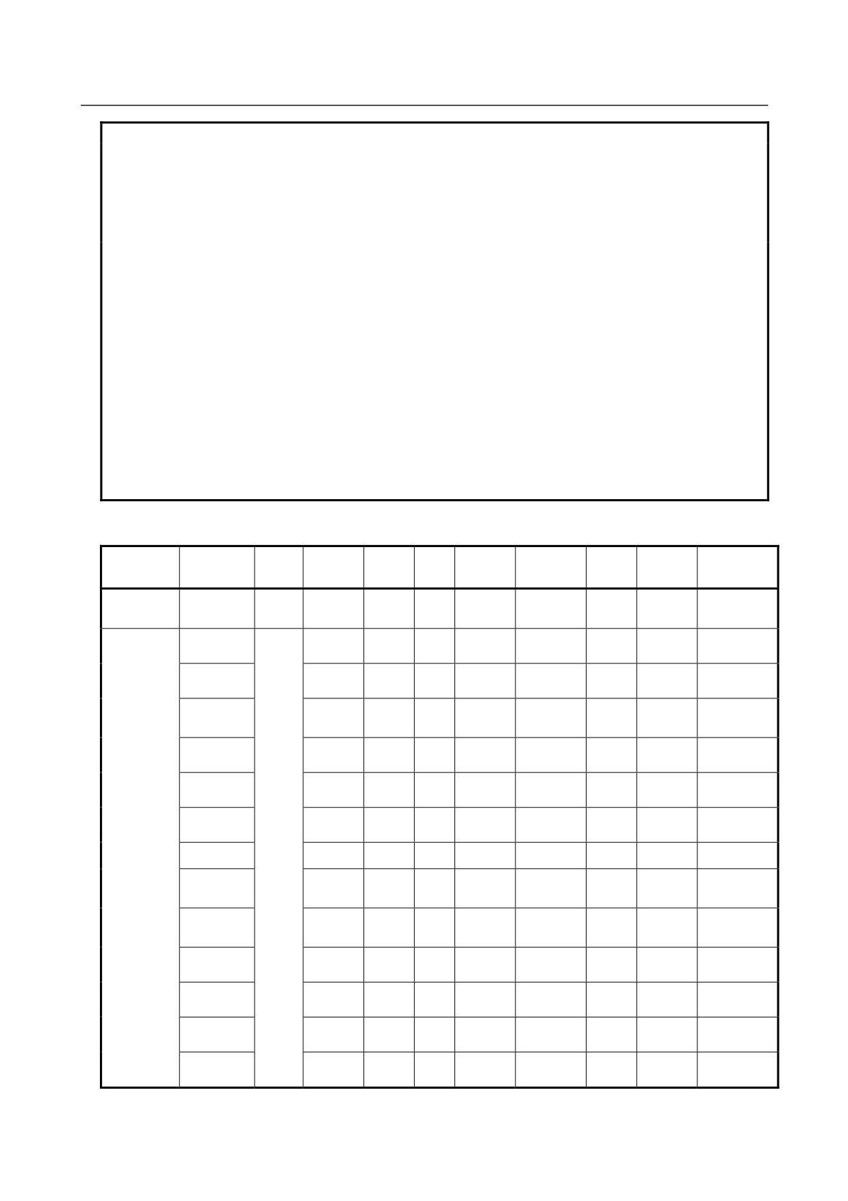
(2) Digital output modules
External
Function to
Module
Rated
Maximum
Polarity
Points/
LED
Output
Output type
Points
connection
detect
name
voltage
current
*1
common
display
protection
*2
abnormalities
Non-insulation
5 to
Not
Not
type DC
AOD32A1
0.3A
NEG
32
8
Connector A
provided
output
24VDC
provided
Terminal
AOD08C
2A
NEG
8
8
Provided
Fuse
block
Terminal
AOD08D
2A
POS
8
8
Provided
Fuse
block
Output
Terminal
AOD08DP
2A
POS
8
8
Provided
protection
Provided
block
device
Terminal
Not
AOD16C
0.5A
NEG
16
8
Provided
block
provided
Terminal
Not
AOD16D
0.5A
POS
16
8
Provided
block
provided
Not
AOD16D2
2A
POS
16
4
Connector C
Provided
provided
Insulation type
12 to
Terminal
AOD16D3
2A
POS
16
4
Provided
Fuse
block B
DC output
4VDC
Output
Terminal
AOD16DP
0.3A
POS
16
8
Provided
protection
block
device
Output
Terminal
AOD16DM
0.3A
POS
16
8
Provided
protection
Provided *5
block
device
Not
Not
AOD32C1
0.3A
NEG
32
8
Connector A
provided
provided
Not
Not
AOD32C2
0.3A
NEG
32
8
Connector B
provided
provided
Not
Not
AOD32D1
0.3A
POS
32
8
Connector A
provided
provided
Not
Not
AOD32D2
0.3A
POS
32
8
Connector B
provided
provided
- 31 -
5. DIGITAL INPUT/OUTPUT
MODULES
CONNECTION
B-61813E/06
External
Function to
Module
Rated
Maximum
Polarity
Points/
LED
Output
Output type
Points
connection
detect
name
voltage
current
*1
common
display
protection
*2
abnormalities
Terminal
AOA05E
2A
-
5
1
Provided
Fuse
100 to
block
240VAC
Terminal
AC output
AOA08E
1A
-
8
4
Provided
Fuse
block
100 to
Terminal
AOA12F
0.5A
-
12
6
Provided
Fuse
120VAC
block
Maximu
Terminal
Not
AOR08G
m
4A
-
8
1
Provided
block
provided
250VAC
/
Terminal
Not
RELAY output
AOR16G
2A
-
16
4
Provided
30VDC
block
provided
Not
AOR16H2
30VDC
2A
-
16
4
Connector B
Provided
provided
(3) Digital input/output hybrid module
External
Input/output
Module
Rated
Polarity
Points/
LED
Output
Additional
Specification
Points
connection
type
name
voltage
*1
common
display
protection
function
*2
Current rating:
7.5 mA
Non-insulation
24VDC
Response
Both
24
24
Connector A
type DC input
time: 20 ms
(shared by
Not
AIO40A
(maximum)
input and
Not provided
provided
Maximum
output
Non-insulation
current:
signals)
type DC
24VDC
NEG
16
16
0.2 A/point and
output
2A for common
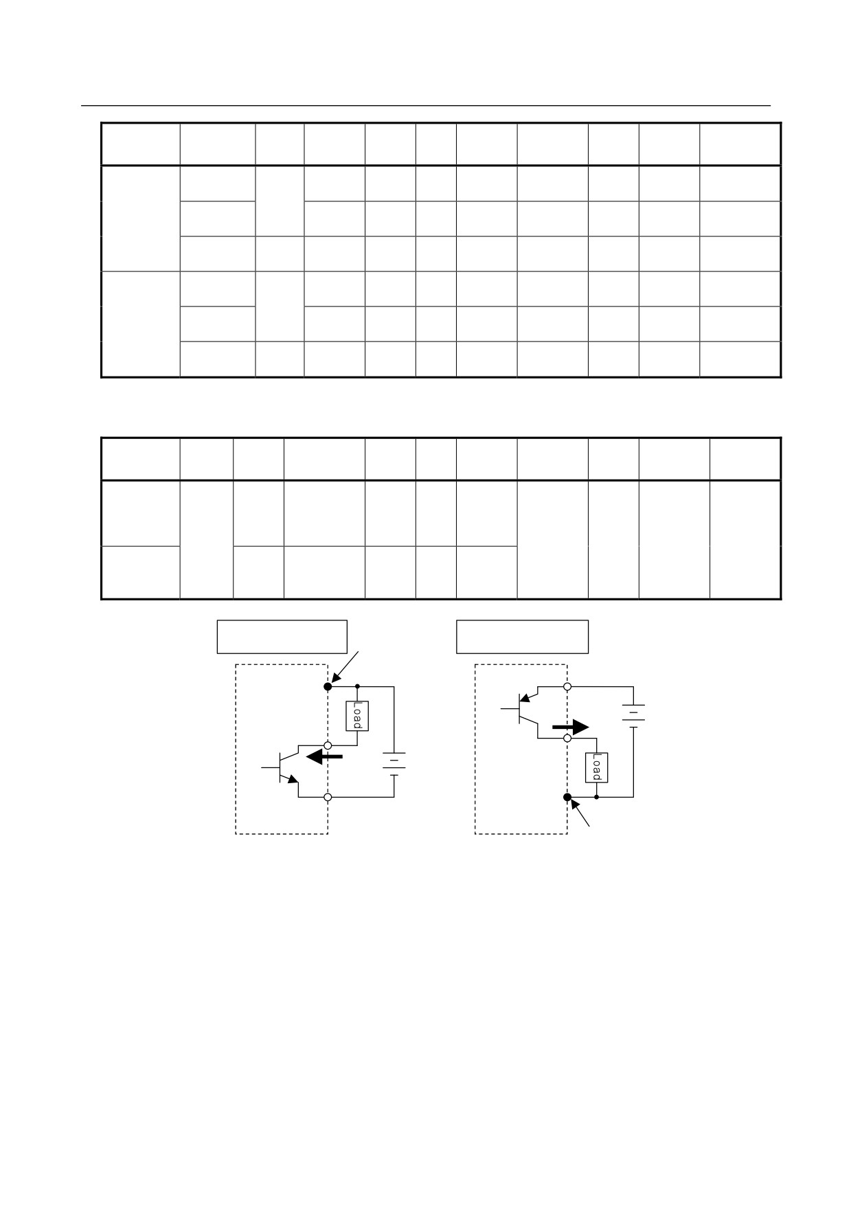
NEG circuit example
POS circuit example
Common pin
+24V
+24V
+
Current
Output pin
+
-
Output pin
Current
-
0V
0V
Common pin
Output module
Output module
- 32 -
5.DIGITAL INPUT/OUTPUT
B-61813E/06
CONNECTION
MODULES
WARNING
1 If the load current of a module with no built-in fuse exceeds its rating continuously
for a long time, it is likely that smoke or ignition may occur. In order to prevent
burnout, it is recommended to use a fuse rated twice the output rating at every
external terminal.
2 Some modules have a built-in fuse for each common. However, no such output
module can be protected from overload. Be sure to use them within their rating. In
order to protect modules from overload, it is recommended to attach an external
fuse to each of them.
3 It is likely that, if a short circuit occurs, an external fuse (even if provided) for an
output module may fail to protect its components. If an external load is
short-circuited, ask for repair.
4 As for modules having an output protection element, the protection function is
intended to protect the components internal to the modules rather than external
units.
5 No protection function of modules can protect their internal components in all
cases. Once any protection function has worked, remove the cause promptly. If an
absolute maximum rating is exceeded, for example, it is likely that protection
functions may not work or an IC may break down before the related protection
function works, depending on the way or situation in which the modules are used.
6 If an output protection function is defective, it is likely that, if the load current
exceeds its rating continuously for a long time, smoke or ignition may occur.
NOTE
1 Polarity
NEGative : (Current sink type)
Output is at Low level when ON.
POSitive : (Current source type)
Output is at High level when ON.
2 Connector and terminal block B
(Section 5.4 shows a connector signal arrangement diagram as viewed from the
front of the module.)
Connector A
: HONDA TSUSHIN MR-50RMA connector (male)
It is recommended that the MR-50LW (housing) and MR50-FH
(soldering-type connector) or MRP-50F01 (crimp connector) +
MRP-F112 (contact) be used on the cable.
Connector B
: HIROSE ELECTRIC HIF3BB-50PA-2.54DS
It is recommended that the HIF3BB-50D-2.54R (press-mount
connector) be used on the cable.
Connector C
: HIROSE ELECTRIC HIF4-40P-3.18DS
It is recommended that the HIF4-40D-3.18R (press-mount
connector) be used on the cable.
Terminal block B : Weidmüller BL3.5/24/90F
The terminal block for the cable comes with the module.
3 For the details of the specifications for each module, refer to the section 5.3.
4 The maximum current of the DC output module includes the permissible rush
current.
5 The I/O Link i status alarms are supported.
- 33 -
5. DIGITAL INPUT/OUTPUT
MODULES
CONNECTION
B-61813E/06
5.2
CORRESPONDENCE BETWEEN I/O SIGNALS AND
ADDRESSES IN A MODULE
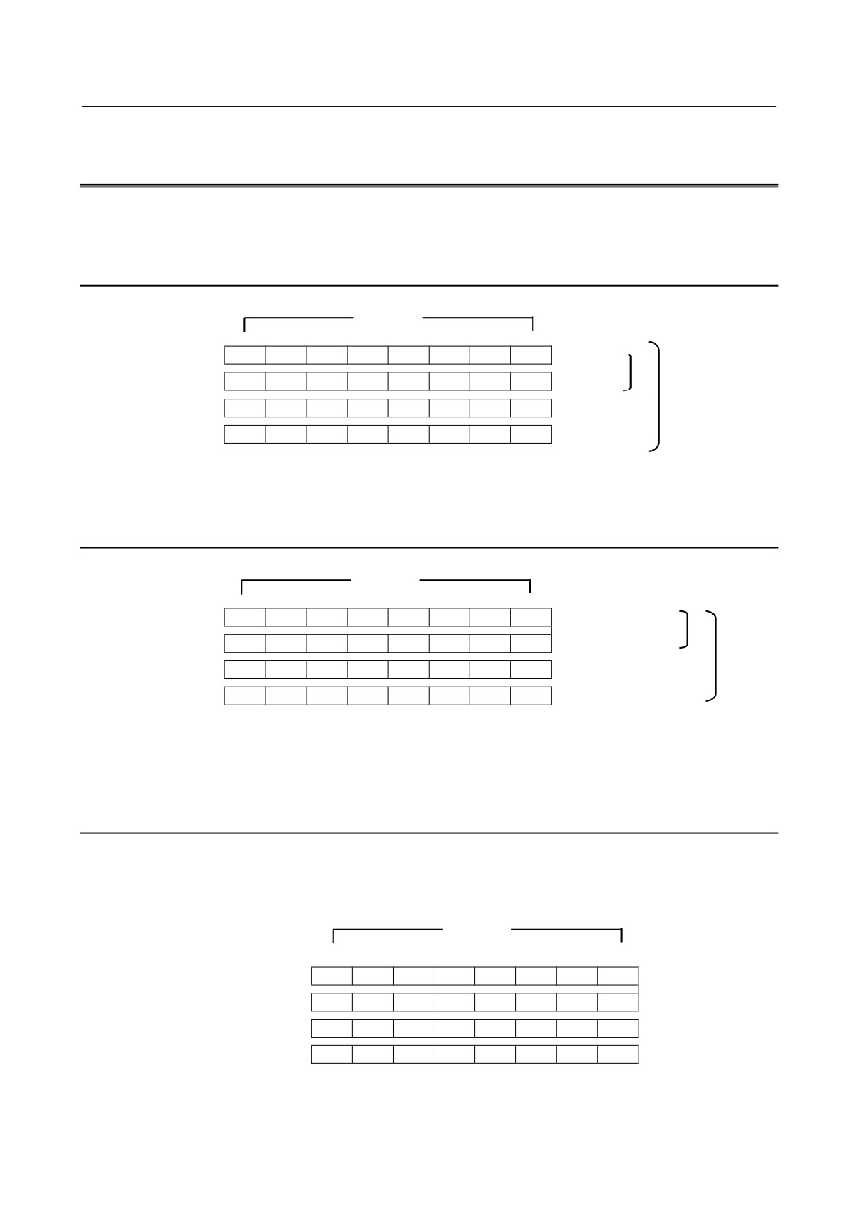
The term "address in a module" refers to an address allocated within each DI/DO module and relative to the
start address (Xm, Yn) of the module.
5.2.1
Module with 16/32 Digital Inputs (DI)
Input bits
Address in the
7
6
5
4
3
2
1
0
module
Xm
A7
A6
A5
A4
A3
A2
A1
A0
DI module of
16 points
Xm+1
B7
B6
B5
B4
B3
B2
B1
B0
DI module of
Xm+2
C7
C6
C5
C4
C3
C2
C1
C0
32 points
Xm+3
D7
D6
D5
D4
D3
D2
D1
D0
When a contact connected to an input of an input module is closed, the corresponding input signal becomes
"1".
5.2.2
Module with 5/8/12/16/32 Digital Outputs (DO)
Output bits
Address in the
DO module of 5
7
6
5
4
3
2
1
0
module
and 8 points
Yn
A7
A6
A5
A4
A3
A2
A1
A0
DO module of 12
Yn+1
B7
B6
B5
B4
B3
B2
B1
B0
and 16 points
Yn+2
C7
C6
C5
C4
C3
C2
C1
C0
DO module of
Yn+3
D7
D6
D5
D4
D3
D2
D1
D0
32 points
When the output signal from an output module is "1", the corresponding output contact (or transistor) is
closed.
5.2.3
AIO40A Module (Hybrid Module with 24 Input and 16 Output
Points)
The allotment of this module requires 4 input and 2 output bytes.
Input byte 4 (Xm + 3) is invalid.
Input section
Input bits
Address in the
7
6
5
4
3
2
1
0
module
Xm
A7
A6
A5
A4
A3
A2
A1
A0
Xm+1
B7
B6
B5
B4
B3
B2
B1
B0
Xm+2
C7
C6
C5
C4
C3
C2
C1
C0
Xm+3
-
-
-
-
-
-
-
-
- 34 -