FANUC AC SERVO MOTOR ai series, AC SPINDLE MOTOR ai series, SERVO AMPLIFIER ai series. MAINTENANCE MANUAL - page 8
No.
Description
Action
Although optional parameter for the output
Check setting of the parameter for output
06
switching option is not set, low-speed winding is
switching and the power line status signal
selected (RCH = 1).
(RCH).
Although Cs contour control mode is input, neither
07
SFR (forward rotation signal) nor SRV (reverse
Check the sequence.
rotation signal) is input.
Although servo mode (rigid tapping or spindle
positioning) control command is input, neither SFR
08
Check the sequence.
(forward rotation signal) nor SRV (reverse rotation
signal) is input.
Although spindle synchronization control command
09
is input, neither SFR (forward rotation signal) nor
Check the sequence.
SRV (reverse rotation signal) is input.
10
Although Cs contour control command is input,
Do not specify another mode during
another operation mode (servo mode, spindle
execution of the Cs contour control
synchronization, or orientation) is specified.
command. Before entering another mode,
cancel the Cs contour control command.
11
Although servo mode (rigid tapping or spindle
Do not specify another mode during
positioning) is input, another operation mode (Cs
execution of the servo mode command.
contour control, spindle synchronization, or
Before entering another mode, cancel
orientation) is specified.
servo mode.
12
Although spindle synchronization is input, another
Do not specify another mode during
operation mode (Cs contour control, servo mode, or
execution of the spindle synchronization
orientation) is specified.
command. Before entering another mode,
cancel the spindle synchronization
command.
13
Although orientation specification is input, another
Do not specify another mode during
operation mode (Cs contour control, servo mode, or
execution of the spindle synchronization
synchronization control) is specified.
command. Before entering another mode,
cancel the spindle synchronization
command.
14
The SFR (forward rotation signal) and SRV
Input one of the SFR and SRV signals.
(reverse rotation signal) are input at the same time.
16
Although the parameter not to use the differential
Check the setting of the parameter and the
speed control function (bit 5 of parameter No. 4000
differential speed mode command
= 0) is set, DEFMD (differential speed mode
command) is input.
17
The parameter settings for the speed detector (bits
Check the setting of the parameter.
2, 1, and 0 of parameter No. 4011) are invalid.
There is no speed detector that matches the
settings.
α+ series SERVO AMPLIFIER
TITLE
for 30+-B Start-up and
Maintenance manual
B-65285EN/03-02/04
NO.
EDT.
DATE
DESIG.
DESCRIPTION
PAGE
30 / 79
No.
Description
Action
18
Although parameter settings are such that that
Check the setting of the parameter and the
there is no position sensor (position control is not to
input signal.
be performed, that is, "bits 3, 2, 1, and 0 of
parameter No. 4002 are, respectively, 0, 0, 0, and
0," a position coder-based orientation command
has been issued.
19
Although magnetic sensor orientation command is
Do not specify another mode during
input, another operation mode (Cs contour control,
execution of the orientation command.
servo mode, or spindle synchronization) is
Before entering another mode, cancel the
specified.
orientation command.
21
A tandem operation command was input when
Input a tandem operation command after
spindle synchronous control is enabled.
canceling spindle synchronous control.
22
Spindle synchronous control was specified when
Specify spindle synchronous control after
tandem operation is enabled.
canceling torque tandem operation.
23
A tandem operation command is input even if the
Torque tandem control requires the CNC
option is not specified.
software option. Check the option.
24
Although continuous indexing in position
Check the INCMD (incremental command).
coder-based orientation is to be performed, an
Be sure to perform absolute position
absolute position command (INCMD = 0) has been
command-based orientation before an
issued after incremental operation (INCMD = 1).
absolute position command.
26
Parameter settings are made to use both spindle
Check the parameter settings and input
switching and three stage speed range switching
signals.
control.
29
Parameter settings are such that the shortest-time
The shortest-time orientation function
orientation function is to be used (bit 6 of parameter
cannot be used in the αi series spindle
No. 4018 is 0 and parameter Nos. 4320 to 4323 are
amplifier. Use a different type of
nonzero).
orientation.
30
The magnetic pole undetected state is set, but a
In the magnetic pole undetected state
command is input.
(EPFIXA=0), the motor cannot be driven
even if a command is input. input a
command in the magnetic pole detection
completed state (EPFIXA=1).
While EPFSTR=1 is set, a command is
ignored even in the magnetic pole detection
completed state, and this error is indicated.
Upon completion of magnetic pole detection,
set EPFSTR=0.
31
This hardware configuration does not support the
Check the CNC model.
use of the spindle FAD function. In this case, the
motor is not activated.
32
Although S0 is not specified for the speed mode, the
Specify S0 for the speed mode before
parameter setting is made to enable the disturbance
enabling the disturbance input function (
input function (bit 7 of parameter No.4395 =1).
setting bit 7 of parameter No.4395 to 1).
α+ series SERVO AMPLIFIER
TITLE
for 30+-B Start-up and
Maintenance manual
B-65285EN/03-02/04
NO.
EDT.
DATE
DESIG.
DESCRIPTION
PAGE
31 / 79
No.
Description
Action
33
This hardware configuration does not support the
Check the CNC model.
use of the spindle EGB function. In this case, the
motor is not activated.
34
Both spindle FAD function and spindle EGB function
These functions cannot be used at the same
are enabled. In this case, the motor is not activated.
time. Enable only one of the functions
35
ID information of the spindle amplifier cannot be
Replace the spindle amplifier with one for
obtained.
which correct ID information is written
36
The SSM is abnormal.
For actioon to be taken for this error, see
(1) The interface signal between the spindle
Section 1.4.”SUB MODULE SM”, in Part IV
anplifier(SP) and SSM is disconnect.
in FANUC AC SPINDLE MOTOR α+ series
(2) The SSM is faulty.
PARAMETER MANUAL B-65280JA.
37
The current loop setting (parameter No.4012) is
Check the setting of parameter No.4012,
changed.
and turn the power offf, then on again.
38
-Parameters related to inter-spindle amplifier
Check the parameters.
communication are not set correctly.
-Functions that cannot be used together with the
torque tandem function are set.
39
DSCN(disconnection detection disable signal) is
Check the sequence.
input in the state where SFR (forward rotation
Do not input DSCN( disconnection
command), SRV (reverse rotation command), or
detectiondisable signal) while a command
ORCM (orientation command) is input.
for motor activation is input.
43
A setting unavailable with the αiCZ sensor (serial) is
Check the parameters.
made.(*1)
44
The spindle amplifier does not support the control
Check the setting of parameter No.4012.
frequency setting.
α+ series SERVO AMPLIFIER
TITLE
for 30+-B Start-up and
Maintenance manual
B-65285EN/03-02/04
NO.
EDT.
DATE
DESIG.
DESCRIPTION
PAGE
32 / 79
Note
*1 If state error 43 is displayed, check the following items.
<1> The setting is made so that the αiCZ sensor (serial) is used as both of the motor and
spindlesensors. (No.4010#2,1,0=0,1,0 and No.4002#3,2,1,0=0,1,1,0)
<2> Spindle HRV control is not set. (No.4012#7=0)
<3> The use of the differential spindle speed control function is set. (No.4000#5=1)
<4> The use of the spindle switching control function is set. (No.4014#0=1)
<5> The setting is made so that alarms related to position feedback are not detected.
(No.4007#6=1 or No.4016#5=0)
<6> The setting is made so that feedback signal disconnection is not detected. (No.4007#5=1)
<7> The setting is made so that alarms related to threading position detection signal feedback
arenot detected. (No.4016#5=0)
<8> The use of an external one-rotation signal is set. (No.4004#2=1)
<9> The use of a position coder is set. (No.4002#3,2,1,0=0,0,1,0)
<10> The setting is made so that the synchronous built-in spindle motor is driven.
(No.4012#6=1)
<11> The use of inter-spindle amplifier communication is set. (No.4352#7=1 or No.4352#6=1)
<12> The use of the dual check safety function is set.
<13> The use of the spindle tandem function is set. (No.4015#3=1)
<14> The use of the αi CZ sensor (serial) as the motor sensor is set and the dual check safety
function is enabled.
α+ series SERVO AMPLIFIER
TITLE
for 30+-B Start-up and
Maintenance manual
B-65285EN/03-02/04
NO.
EDT.
DATE
DESIG.
DESCRIPTION
PAGE
33 / 79
2. TROUBLESHOOTING
2.1.
TROUBLESHOOTING PROCEDURES
2.1.1
Troubleshooting Procedure
Smart trouble shooting function is available for the combination of the 30+-B series CNC and the α+ servo
amplifier for the 30+-B series. The function analyzes causes of alarm occurrence and shows how to remove them.
At alarm occurrence, switch from he CNC screen to the “Trouble diagnosis guidance” screen and remove the cause
of the alarm according to what is displayed on the screen.
⇒ 2.2 SMART TROUBLE SHOOTING FUNCTION
⇒ 2.2.1 Failure Diagnosis Guidance
IMPORTANT
・ Using the failure diagnosis guidance requires keeping it in the “SAMPLING” status. See
Subsection 2.2.3 for explanations about how to shift to the “SAMPLING” status.
Data (about power supply, motor current, and detector) related to servo amplifiers before alarm and just at alarm
are sent to the CNC immediately. This data can be used in taking action for alarm occurrence.
Data (about power supply, motor current, and detector) related to servo amplifiers is saved to the CNC immediately
before and at alarm occurrence. This data can be used in taking action for alarm occurrence.
⇒ 2.2.2 Failure Diagnosis Monitor
IMPORTANT
・ The failure diagnosis monitor has two status, “SAMPLING” and “LATCHED”.
If you want to monitor data at future alarm occurrence, perform “CLEAR”. If you want to save
the conditions at past alarm occurrence, do not perform “CLEAR”. See Subsection 2.2.3 for
detailed descriptions of this procedure.
See Section 2.3 for lists of CNC alarm numbers related to servos and LED indication numbers on servo amplifiers.
NOTE
・ There might be a possibility that you cannot get exact analysis even when you use smart
trouble shooting function. In such case, identify the alarm number, the program where the
alarm occur, and what you operated, and then make a service call.
α+ series SERVO AMPLIFIER
TITLE
for 30+-B Start-up and
Maintenance manual
B-65285EN/03-02/04
NO.
EDT.
DATE
DESIG.
DESCRIPTION
PAGE
34 / 79
2.2.
SMART TROUBLE SHOOTING FUNCTION
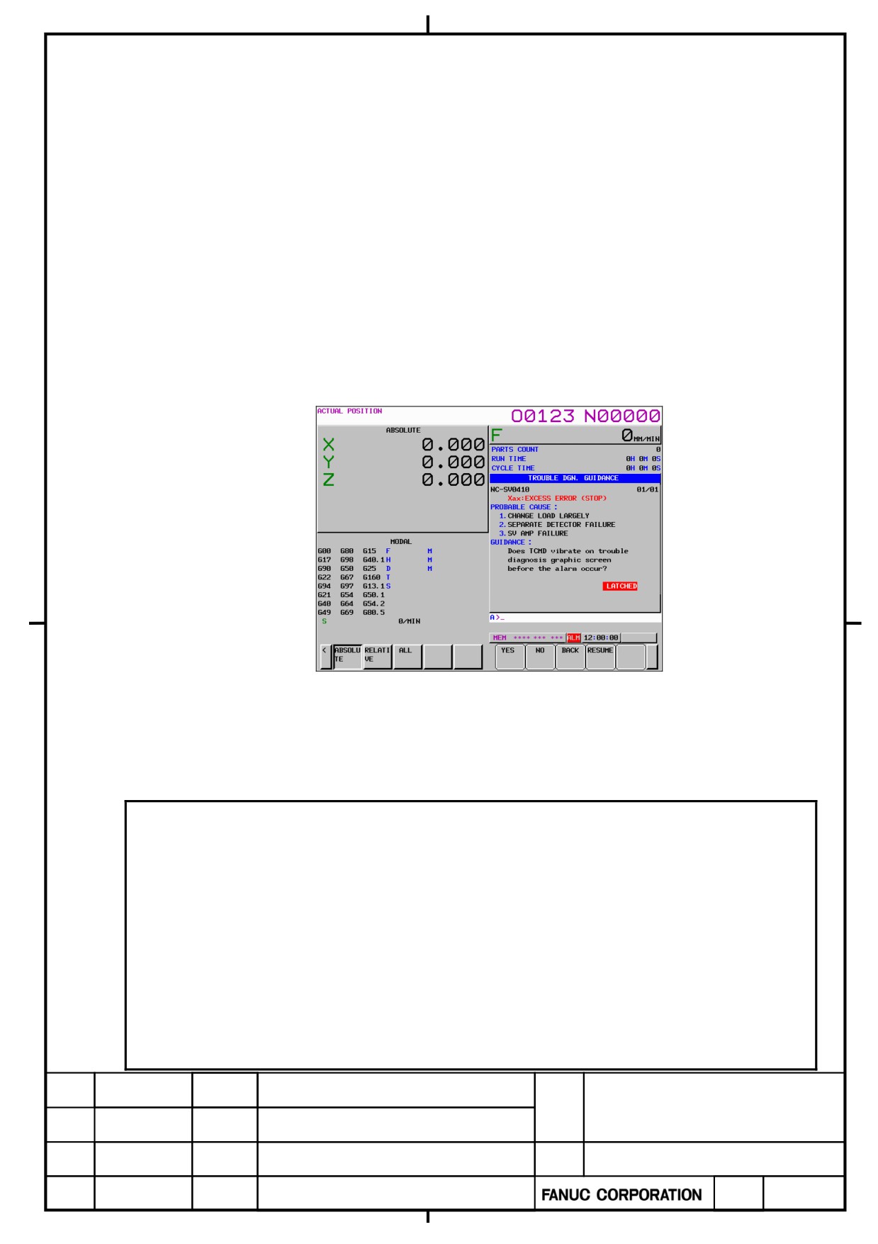
The 30+-B series CNC has a function for failure diagnosis. With this function, the operator can get diagnostic
information that may be useful to make decisions at the occurrence of a servo, spindle, or CNC alarm from the
CNC screen.
The major features of the smart trouble shooting function are as follows:
・ “Trouble diagnosis guidance” screen for figuring out alarm causes according to the failure diagnosis flow
・ “Trouble diagnosis monitor” screen for monitoring the states of servo circuits and spindles during normal
operation and enabling data to be latched at alarm occurrence
・ “Trouble diagnosis graphic” screen for making it possible to display waveforms observed at the occurrence
of a servo or spindle alarm
In all of these features, the “Trouble diagnosis guidance” screen can be used to identify an alarm cause and how
to handle it quickly, leading to a possible improvement in facility availability ratio due to a reduction of down time.
Shown below is an example of the “Trouble diagnosis guidance” screen.
Trouble diagnosis guidance screen
The failure diagnosis guidance executes a diagnosis flow to identify these causes. Many analyses are made
automatically according to information inside of CNC. However, questions may be displayed on the guidance
screen in making some analyses. Answer the questions using the soft key [YES] or [No] to proceed on the
guidance flow.
NOTE
・ “PROBABLE CAUSE” and “GUIDANCE” (how to handle) show the most likely information
obtained. Before any replacement, make a double check using another method (for example,
detecting an insulation resistance or checking conductivity).
・ In case that the result of the diagnosis is “Failure of amplifier” when “SV ABNORMAL
CURRENT” alarm (SV438) or “OVERCURRENT POWER CIRCUIT” alarm (SP9012) or “SV
IPM ALARM” (SV449) occurs, check the insulation of power wire and motor between lines to
ground before replacing the amplifier.
・ In case that the result of the diagnosis is “Failure of motor or power cable” when “SV
ABNORMAL CURRENT” alarm (SV438) or “OVERCURRENT POWER CIRCUIT” alarm
(SP9012) or “SV IPM ALARM” (SV449) occurs, check also the insulation of power wire and
motor between lines to ground.
α+ series SERVO AMPLIFIER
TITLE
for 30+-B Start-up and
Maintenance manual
B-65285EN/03-02/04
02
2011.10.12
NOTE is added
NO.
EDT.
DATE
DESIG.
DESCRIPTION
PAGE
35 / 79
2.2.1
Failure Diagnosis Guidance
IMPORTANT
・ Using the failure diagnosis guidance requires keeping it in the “SAMPLING” status. See
Subsection 2.2.3 for explanations about how to shift to the “SAMPLING” status.
Explained below is how to use the failure diagnosis guidance to identify the causes of alarm occurrence, using
SV011 (“EXCESS ERROR (MOVING)”) and SV0449 (“SV IPM ALARM”) as examples.
Alarm example 1) Occurrence of SV0411 (“EXCESS ERROR (MOVING)”)
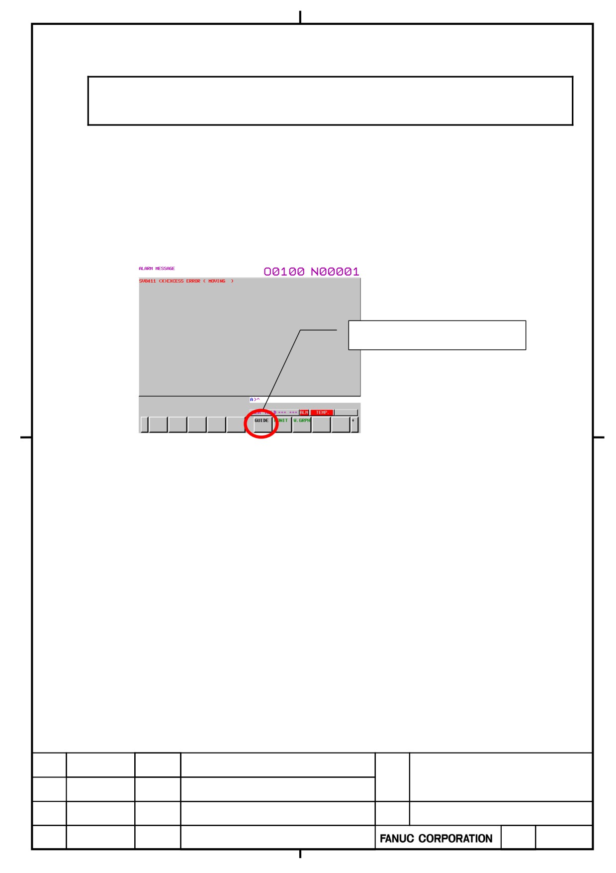
(1) At alarm occurrence, follow the steps below to display the “Trouble diagnosis guidance” screen.
<1> If no alarm screen appears, press the Message key.
<2> Keep pressing the continuation menu key [>] until the soft key [GUIDE] appears.
<3> Press the soft key [GUIDE] .
Press [GUIDE] key
(2) There are some causes to occur EXCESS ERROR as follows.
Amplifier abnormal
Power wire or motor winding short-circuited
Power wire or motor winding broken
Servo-off signal malfunctioning
Excessive load fluctuation
Brake faulty
Command for speed higher than specification issued
The failure diagnosis guidance executes a diagnosis flow to identify these causes. Many analyses are made
automatically according to information within the NC. However, questions may be displayed on the
guidance screen in making some analyses. Answer the questions using the soft key [YES] or [NO] to
proceed on the guidance flow.
α+ series SERVO AMPLIFIER
TITLE
for 30+-B Start-up and
Maintenance manual
B-65285EN/03-02/04
NO.
EDT.
DATE
DESIG.
DESCRIPTION
PAGE
36 / 79
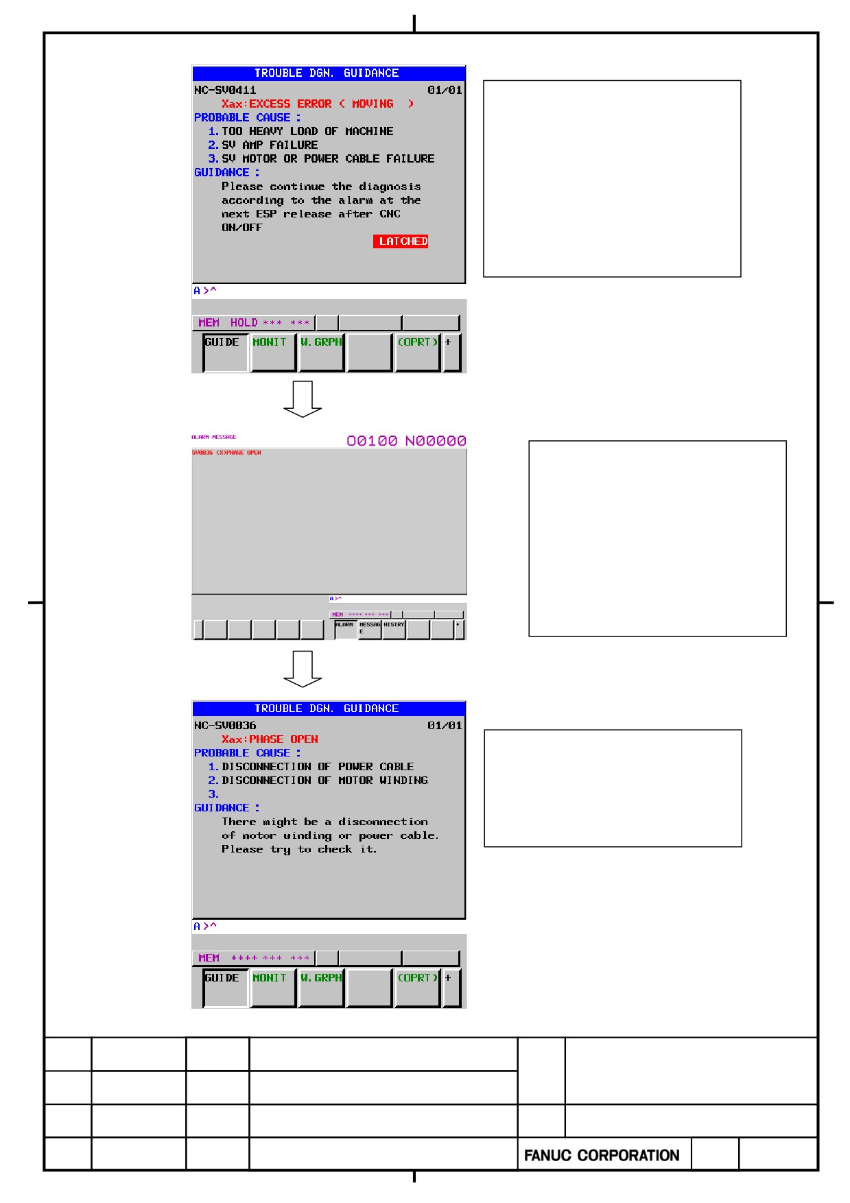
Example)
“EXCESS ERROR (MOVING)” resulting from a broken power wire
Pressing [GUIDE] causes the
message shown on the left to appear.
The guidance requests you to turn off
the power once. After the servo
amplifier is turned off and on again,
self-diagnosis is conducted.
Just after the servo amplifier is turned
on, self-diagnosis was conducted, and
the “PHASE OPEN” alarm occurred.
Press the [GUIDE] button again to
display the “Trouble diagnosis
guidance” screen.
The [Trouble diagnosis guidance]
screen suggests a possible broken
motor winding or power wire. Take
action as directed by the message.
α+ series SERVO AMPLIFIER
TITLE
for 30+-B Start-up and
Maintenance manual
B-65285EN/03-02/04
NO.
EDT.
DATE
DESIG.
DESCRIPTION
PAGE
37 / 79
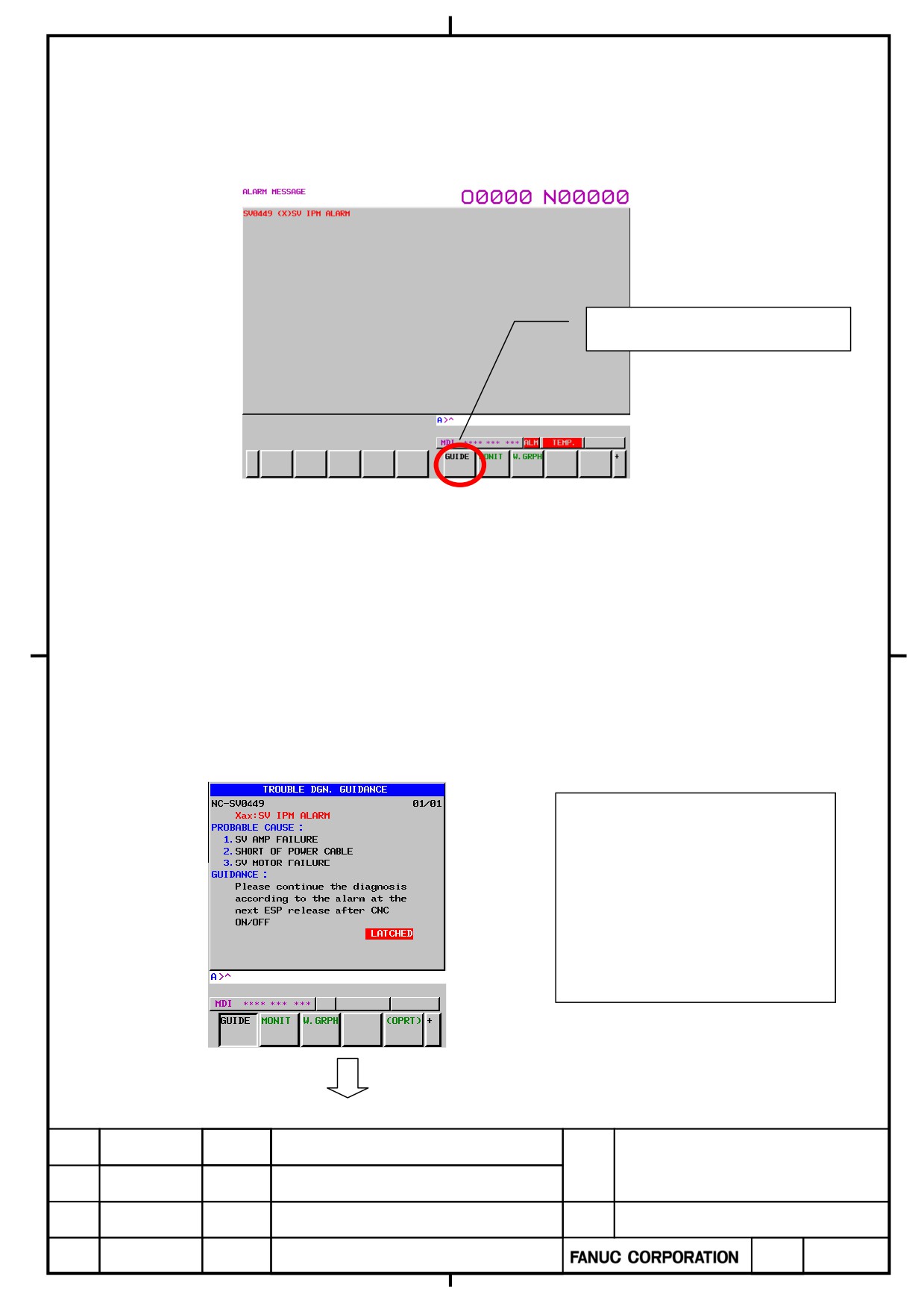
Alarm example 2) Occurrence of SV0449 ([SV IPM alarm])
(1) At alarm occurrence, follow the steps below to display the “Trouble diagnosis guidance” screen.
<1> If no alarm screen appears, press the Message key.
<2> Keep pressing the continuation menu key [>] until the soft key [GUIDE] appears.
<3> Press the soft key [GUIDE] .
Press [GUIDE] key
(2) There are some causes to occur “SV IPM alarm” as follows.
Amplifier abnormal
Power wire or motor winding short-circuited
Power wire or motor winding broken
Current control disturbed
The failure diagnosis guidance executes a diagnosis flow to identify these causes. Many analyses are made
automatically according to information within the NC. However, questions may be displayed on the
guidance screen in making some analyses. Answer the questions using the soft key [YES] or [NO] to
proceed on the guidance flow.
Example)
“SV IPM alarm” resulting from a broken power wire
Pressing [GUIDE] causes the message
shown on the left to appear. The
guidance requests you to turn off the
power once. After the servo amplifier
is turned off and on again,
self-diagnosis is conducted.
α+ series SERVO AMPLIFIER
TITLE
for 30+-B Start-up and
Maintenance manual
B-65285EN/03-02/04
NO.
EDT.
DATE
DESIG.
DESCRIPTION
PAGE
38 / 79
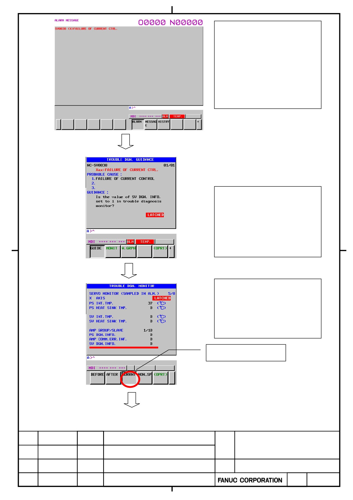
Just after the servo amplifier is turned
on, self-diagnosis was conducted, and
the “FAILURE OF CURRENT
CTL” alarm occurs. Display the
“Trouble diagnosis guidance” screen
again.
The guidance displays “Is the value of
SV DGN. INFO. set to 1 in trouble
diagnosis monitor”. So, view the
“Trouble diagnosis monitor”
screen.
Display the “Trouble diagnosis
monitor” screen, go to the page
containing the item “SV DNG.
INFO.”, and then press the
[CURRENT] button.
Press [CURRENT] key
α+ series SERVO AMPLIFIER
TITLE
for 30+-B Start-up and
Maintenance manual
B-65285EN/03-02/04
NO.
EDT.
DATE
DESIG.
DESCRIPTION
PAGE
39 / 79
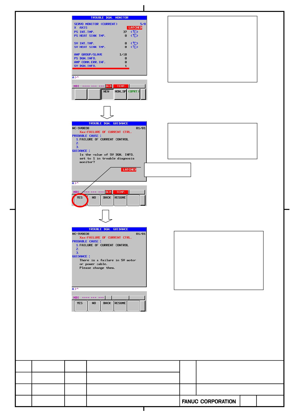
Check the value of [SV DNG INFO],
which is either [0] or [1].
[1] means that a short-circuited power
cable or motor winding was detected
at servo amplifier self-diagnosis.
Display the “Trouble diagnosis
guidance” screen, and press [YES] on
the screen.
Press [YES] key
The guidance suggests a possibility of
short-circuited power wire or motor
winding.
Take action according to the message.
α+ series SERVO AMPLIFIER
TITLE
for 30+-B Start-up and
Maintenance manual
B-65285EN/03-02/04
NO.
EDT.
DATE
DESIG.
DESCRIPTION
PAGE
40 / 79
2.2.2
Failure Diagnosis Monitor
IMPORTANT
・ The failure diagnosis monitor has two status, “SAMPLING” and “LATCHED”.
If you want to monitor data at future alarm occurrence, perform “CLEAR”. If you want to save
the conditions at past alarm occurrence, do not perform “CLEAR”. See Subsection 2.2.3 for
detailed descriptions of this procedure.
The failure diagnosis monitor can display the following information.
Follow the steps below to display the “Trouble diagnosis monitor” screen.
・ Press the Message key to display the alarm screen.
・ Keep pressing the continuation menu key [>] until the soft key [MONIT] appears.
・ Press the soft key [MONIT] to display the “Trouble diagnosis monitor” screen.
α+ series SERVO AMPLIFIER
TITLE
for 30+-B Start-up and
Maintenance manual
B-65285EN/03-02/04
NO.
EDT.
DATE
DESIG.
DESCRIPTION
PAGE
41 / 79
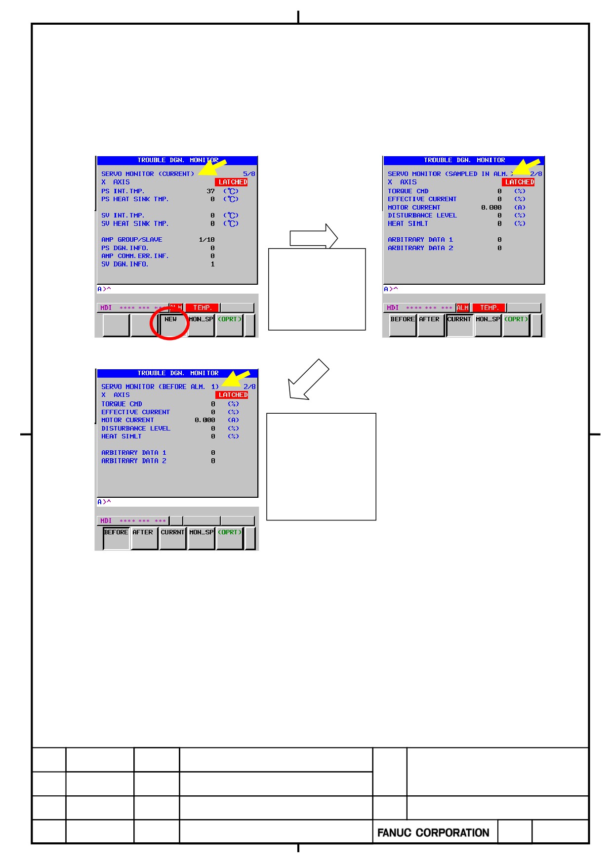
How to check data just before alarm and at alarm occurrence
The failure diagnosis monitor enables the operator to view:
・ Data at the moment
・ Data at alarm occurrence
・ Data some sampling periods before alarm occurrence
At alarm
occurrence,
pressing [NEW]
button:
Current value
The value at time of alarm
Pressing [BEFORE]
button lets the
operator go back 5
sampling periods.
The value before 1 sampling
α+ series SERVO AMPLIFIER
TITLE
for 30+-B Start-up and
Maintenance manual
B-65285EN/03-02/04
NO.
EDT.
DATE
DESIG.
DESCRIPTION
PAGE
42 / 79
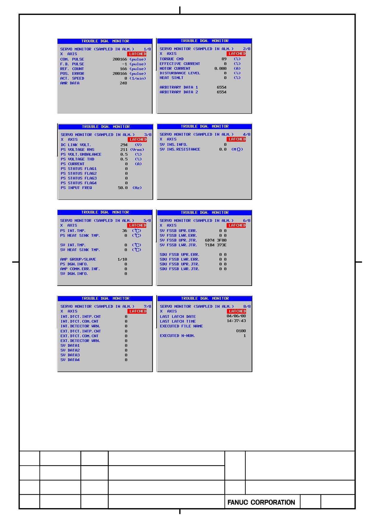
Details of the monitor screens related to servo amplifiers
α+ series SERVO AMPLIFIER
TITLE
for 30+-B Start-up and
Maintenance manual
B-65285EN/03-02/04
NO.
EDT.
DATE
DESIG.
DESCRIPTION
PAGE
43 / 79
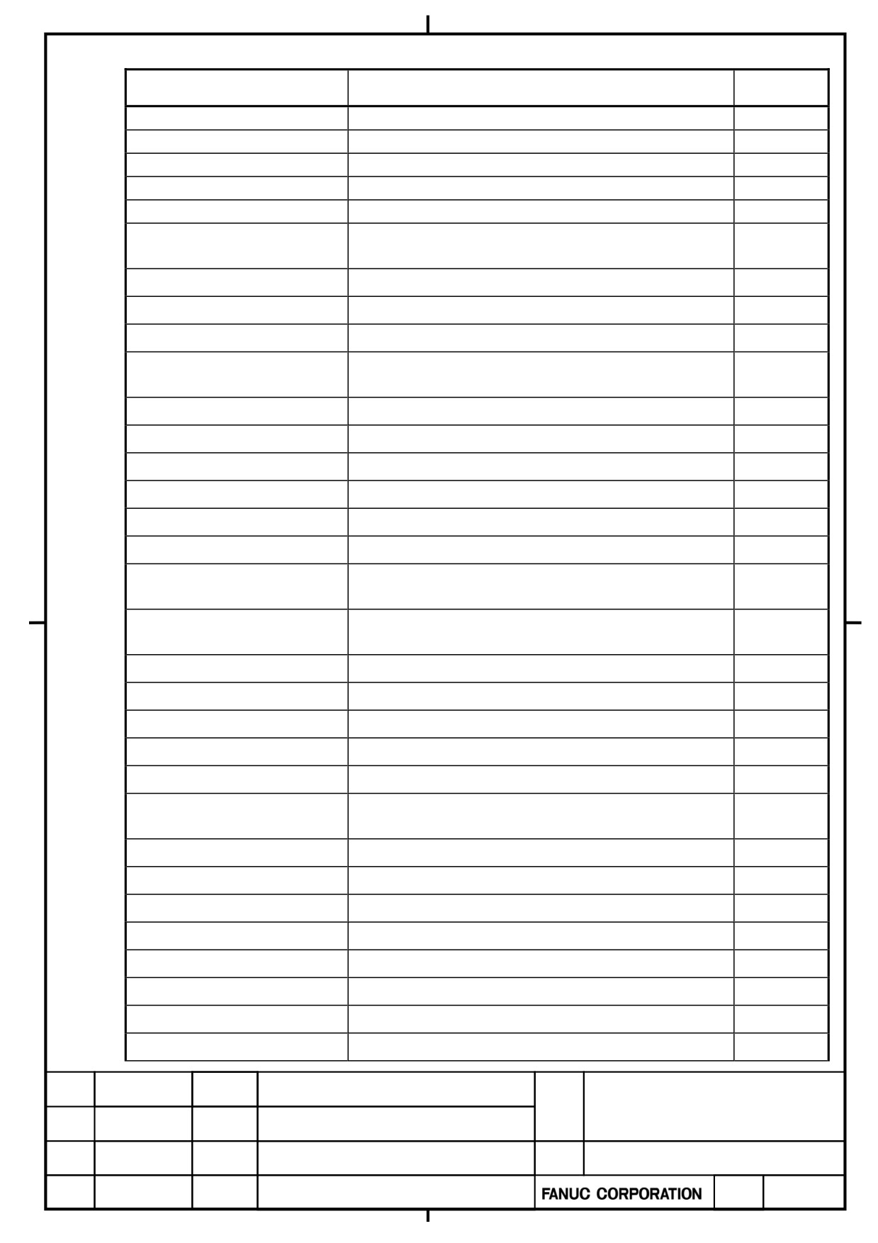
Display
Data(unit)
Data explanation
page No.
COMMAND PULSE (pulse)
1/8
F.B. PULSE (pulse)
(Note 3)
1/8
REF.COUNTER (pulse)
1/8
POS. ERROR (pulse)
1/8
ACTUAL SPEED (1/min)
1/8
AMR DATA
Armature position data of motor (256/1cycle of motor
1/8
current )
Maximum torque =100%
2/8
TORQUE COMMAND (%)
Maximum current of servo amplifier =100%
2/8
EFFECTIVE CURRENT (%)
2/8
MOTOR CURRENT (A)
Alarm level of unexpected disturbance torqe detection
2/8
DISTURBANCE LEVEL (%)
=100%
OVC alarm level =100%
2/8
HEAT SIMULATION (%)
(note2)
2/8
ARBITRARY DATA1
(note2)
2/8
ARBITRARY DATA2
Instantaneous value (Note 3)
3/8
DC LINK VOLT. (V)
Average of 1cycle of input power supply(Note 3)
3/8
PS VOLTAGE RMS (Vrms)
Average of 1cycle of input power supply (Note 3)
3/8
PS VOLT.UMBALANCE (%)
Average of 1cycle of THD(Total Harmonic Distortion)
3/8
PS VOLTAGE THD (%)
(Note 3)
Average of current amplitude of the 1 cycle of input power
3/8
PS CURRENT (A)
supply (Note 3)
(Note 4)
3/8
PS STATUS FLAG 1
(Note 4)
3/8
PS STATUS FLAG 2
(Note 4)
3/8
PS STATUS FLAG 3
(Note 4)
3/8
PS STATUS FLAG 4
Average of 1cycle of input power supply (Note 3)
3/8
PS INPUT FREQ (Hz)
State flage of INSULATION DETERIORATION
4/8
SV INS.INFO.
DETECTION FUNCTION
Insulation resistance (Note 3)
4/8
SV INS.RESISTANCE (MΩ)
(Note 3)
4/8
PS INT.TMP. (℃)
PS HEAT SINK TMP. (℃)
(Note 3)
5/8
SV INT.TMP. (℃)
(Note 3)
5/8
SV HEAT SINK TMP. (℃)
(Note 3)
5/8
AMP GROUP/SLAVE
Groupe No. and Slave No.
5/8
State flage of PS
5/8
PS DGN.INFO.
Error state flage of communication between amplifier
5/8
AMP COMM.ERR.INF.
α+ series SERVO AMPLIFIER
TITLE
for 30+-B Start-up and
Maintenance manual
B-65285EN/03-02/04
NO.
EDT.
DATE
DESIG.
DESCRIPTION
PAGE
44 / 79
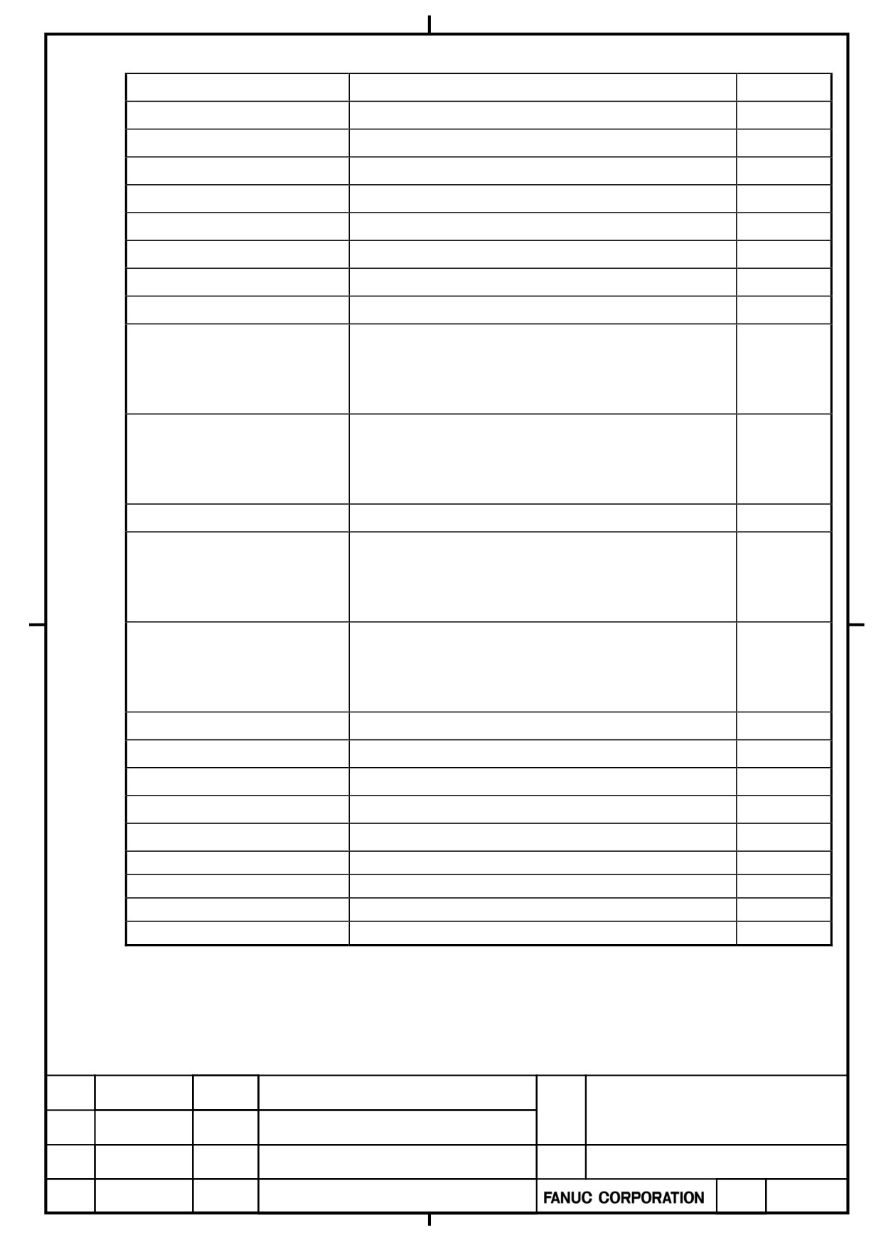
State flage of SV
5/8
SV DGN.INFO.
(Note 5)
6/8
SV FSSB UPR.ERR.
(Note 5)
6/8
SV FSSB LWR.ERR.
(Note 5)
6/8
SV FSSB UPR.JTR.
(Note 5)
6/8
SV FSSB LWR.JTR.
(Note 5)
6/8
SDU FSSB UPR.ERR.
(Note 5)
6/8
SDU FSSB LWR.ERR.
(Note 5)
6/8
SDU FSSB UPR.JTR.
SDU FSSB LWR.JTR.
(Note 5)
6/8
The number of times by which the data of a built-in
7/8
INT.DTCT.INTP.CNT
detector was disturbed in the noise
(The number of times which detected the abnormalities in
data)
The number of times which detected the abnormalities in
7/8
INT.DTCT.COM.CNT
data of a built-in detector
(The number of times which detected the communication
error)
Warning information of a built-in detector
7/8
INT.DETECTOR WRN.
The number of times by which the data of a separated
7/8
EXT.DTCT.INTP.CNT
detector was disturbed in the noise
(The number of times which detected the abnormalities in
data)
The number of times which detected the abnormalities in
7/8
EXT.DTCT.COM.CNT
data of a separated detector
(The number of times which detected the communication
error)
Warning information of a separated detector
7/8
EXT.DETECTOR WRN.
(Note 2)
7/8
SV DATA 1
(Note 2)
7/8
SV DATA 2
(Note 2)
7/8
SV DATA 3
(Note 2)
7/8
SV DATA 4
LAST LATCH DATE
8/8
LAST LATCH TIME
8/8
EXECUTED FILE NAME
8/8
EXECUTED N-NUM
8/8
α+ series SERVO AMPLIFIER
TITLE
for 30+-B Start-up and
Maintenance manual
B-65285EN/03-02/04
NO.
EDT.
DATE
DESIG.
DESCRIPTION
PAGE
45 / 79
NOTE
1 The range of displays listed above is only the one that can be displayed with the monitor function. It
includes neither a system performance nor a rated value.
2 Arbitrary data items 1 and 2 and SV data items 1 to 4 are intended for use by FANUC for
maintenance purposes.
3 The displayed voltage, current, frequency, resistance, and temperature values are approximate
values with some error included. If accurate data is needed, measure them using dedicated
measuring instruments.
4 PS status flags 1 to 4 are intended for use by FANUC for maintenance purposes.
5 FSSB errors and jitter data indicate the status of FSSB communication. They are intended for use
by FANUC for maintenance purposes.
α+ series SERVO AMPLIFIER
TITLE
for 30+-B Start-up and
Maintenance manual
B-65285EN/03-02/04
NO.
EDT.
DATE
DESIG.
DESCRIPTION
PAGE
46 / 79
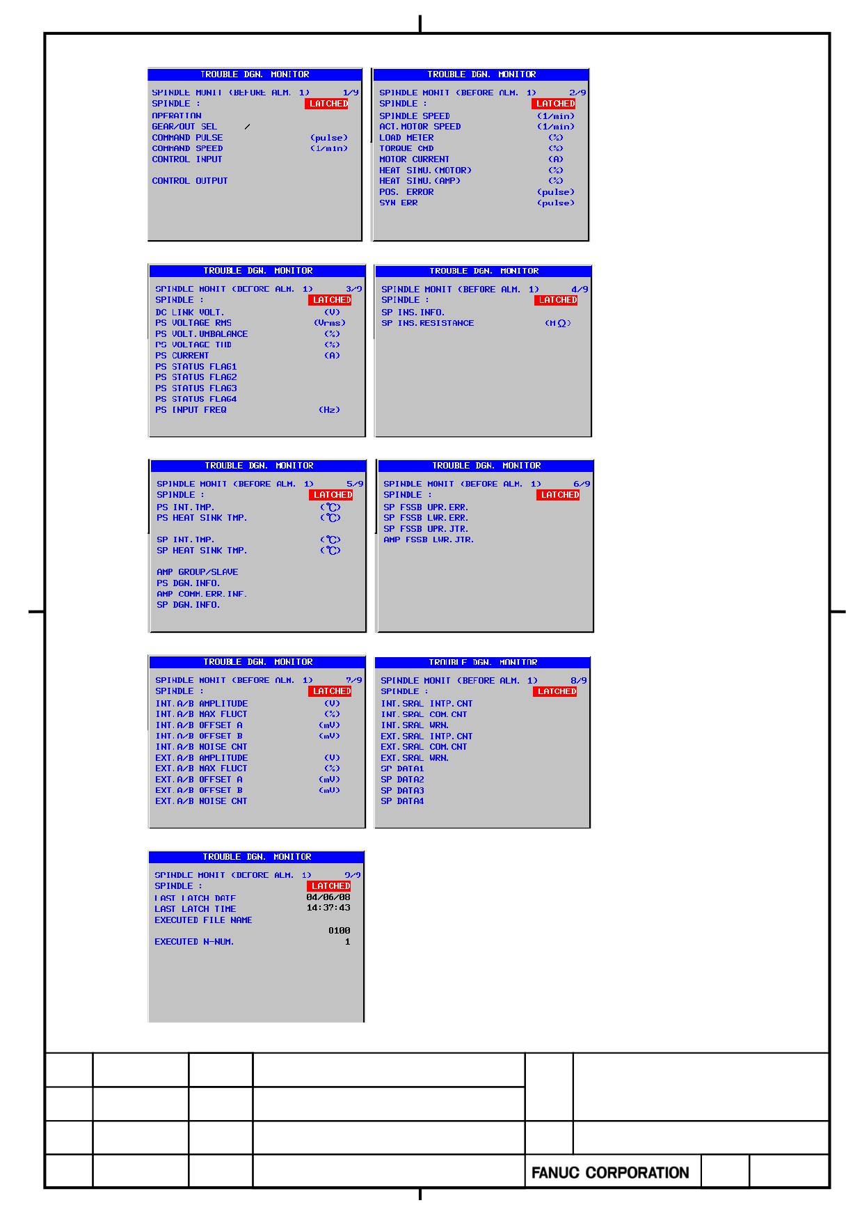
Details of the monitor screens related to spindle amplifiers
α+ series SERVO AMPLIFIER
TITLE
for 30+-B Start-up and
Maintenance manual
B-65285EN/03-02/04
NO.
EDT.
DATE
DESIG.
DESCRIPTION
PAGE
47 / 79
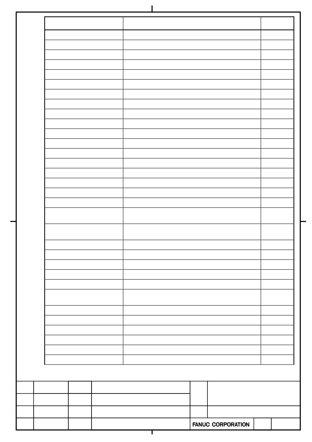
Display
Data(unit)
Data explanation
page No.
1/9
Operation mode
1/9
Gear select command
1/9
Command pulse (pulse)
(Note2)
1/9
Command speed (1/min)
1/9
Input signals
1/9
Output signals
2/9
ACT.SPINDLE SPEED (1/min)
(Note2)
2/9
ACT.MOTOR SPEED (1/min)
2/9
LOAD METER (%)
Maximum torque=100%
2/9
TORQUE COMMAND (%)
2/9
MOTOR CURRENT (A)
OVC alarm level=100%
2/9
HEAT SIMU.(MOTOR) (%)
OVC alarm level=100%
2/9
HEAT SIMU.(AMP) (%)
2/9
POS. ERROR (pulse)
2/9
Synchronization error (pulse)
Instantaneous value (Note 3)
3/9
DC LINK VOLT. (V)
Average of 1cycle of input power supply (Note 3)
3/9
PS VOLTAGE RMS (Vrms)
Average of 1cycle of input power supply (Note 3)
3/9
PS VOLT.UMBALANCE (%)
Average of 1cycle of THD(Total Harmonic Distortion)
3/9
PS VOLTAGE THD (%)
(Note 3)
Average of current amplitude of the 1 cycle of input power
3/9
PS CURRENT (A)
supply (Note 3)
(Note 5)
3/9
PS STATUS FLAG 1
3/9
PS STATUS FLAG 2
(Note 5)
3/9
PS STATUS FLAG 3
(Note 5)
3/9
PS STATUS FLAG 4
(Note 5)
Average of 1cycle of input power supply(
3/9
PS INPUT FREQ (Hz)
State flage of INSULATION DETERIORATION
4/9
SP INS.INFO.
DETECTION FUNCTION
Insulation resistance (Note 3)
4/9
SP INS.RESISTANCE (MΩ)
PS INT.TMP. (℃)
(Note 3)
5/9
PS HEAT SINK TMP. (℃)
(Note 3)
5/9
(Note 3)
5/9
SP INT.TMP. (℃)
(Note 3)
5/9
SP HEAT SINK TMP. (℃)
Groupe No. and Slave No.
5/9
AMP GROUP/SLAVE
α+ series SERVO AMPLIFIER
TITLE
for 30+-B Start-up and
Maintenance manual
B-65285EN/03-02/04
NO.
EDT.
DATE
DESIG.
DESCRIPTION
PAGE
48 / 79
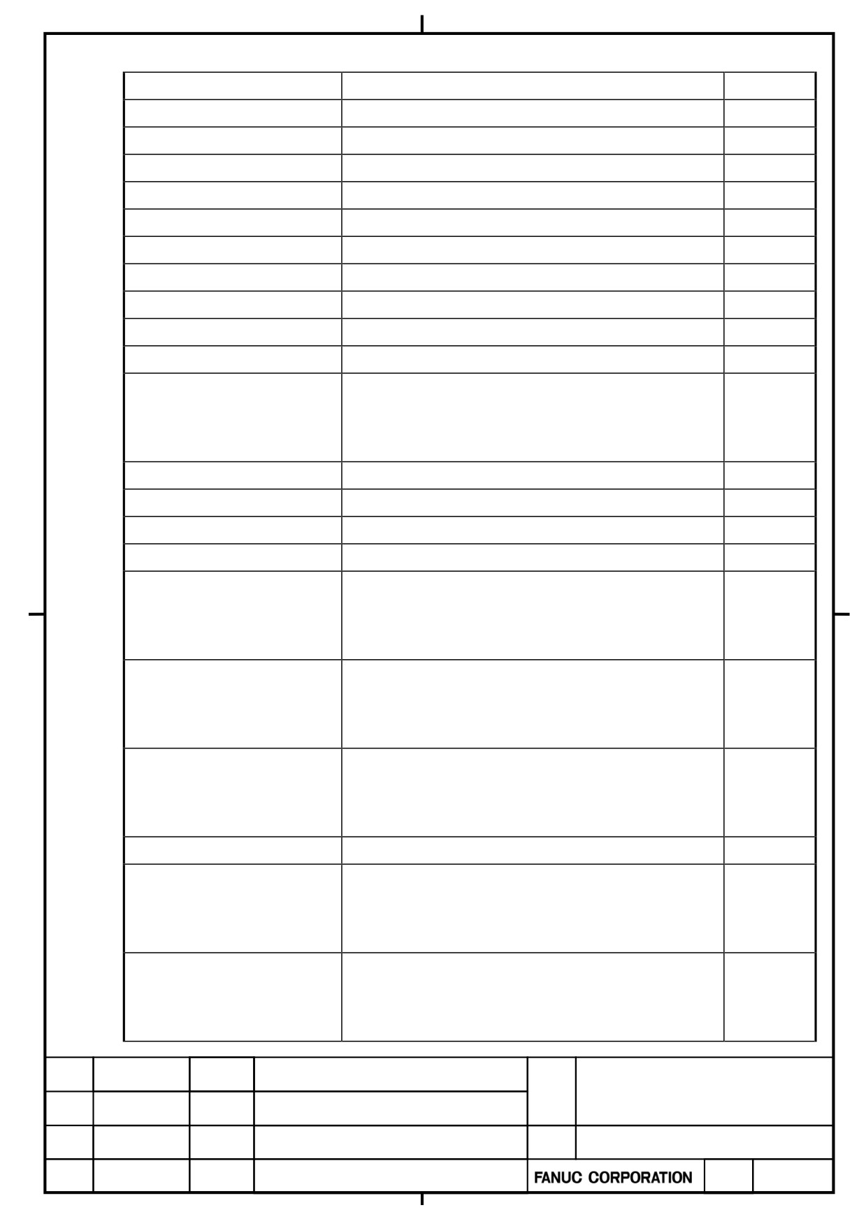
State flage of PS
5/9
PS DGN.INFO.
Error state flage of communication between amplifier
5/9
AMP COMM.ERR.INF.
State flage of SP
5/9
SP DGN.INFO.
(Note 6)
6/9
SP FSSB UPR.ERR.
(Note 6)
6/9
SP FSSB LWR.ERR.
(Note 6)
6/9
SP FSSB UPR.JTR.
(Note 6)
6/9
SP FSSB LWR.JTR.
Amplitude of built-in analog sensor
7/9
INT.A/B AMPLITUDE (V)
INT.A/B MAX FLUCT (%)
Max. fluctuation of built-in analog sensor
7/9
A phase offset of built-in analog sensor
7/9
INT.A/B OFFSET A (mV)
B phase offset of built-in analog sensor
7/9
INT.A/B OFFSET B (mV)
The number of times by which the data of a built-in sensor
7/9
INT.A/B NOISE CNT
was disturbed in the noise
(The number of times which detected the abnormalities in
data)
Amplitude of separated analog sensor
7/9
EXT.A/B AMPLITUDE (V)
Max. fluctuation of separated analog sensor
7/9
EXT.A/B MAX FLUCT (%)
A phase offset of separated analog sensor
7/9
EXT.A/B OFFSET A (mV)
B phase offset of separated analog sensor
7/9
EXT.A/B OFFSET B (mV)
The number of times by which the data of a separated
7/9
EXT.A/B NOISE CNT
analog sensor is disturbed in the noise
(The number of times which detected the abnormalities in
data)
The number of times by which the data of a built-in serial
8/9
INT.SRAL INTP.CNT
sensor is disturbed in the noise
(The number of times which detected the abnormalities in
data)
The number of times which detected the abnormalities in
8/9
INT.SRAL COM.CNT
data of a built-in serial sensor
(The number of times which detected the communication
error)
Warning information of built-in serial sensor
8/9
INT.SRAL WRN.
The number of times by which the data of a separated
8/9
EXT.SRAL INTP.CNT
serial sensor is disturbed in the noise
(The number of times which detected the abnormalities in
data)
The number of times which detected the abnormalities in
8/9
EXT.SRAL COM.CNT
data of a separated serial sensor
(The number of times which detected the communication
error)
α+ series SERVO AMPLIFIER
TITLE
for 30+-B Start-up and
Maintenance manual
B-65285EN/03-02/04
NO.
EDT.
DATE
DESIG.
DESCRIPTION
PAGE
49 / 79
Warning information of separated serial sensor
8/9
EXT.SRAL WRN.
(Note 4)
8/9
SP DATA 1
(Note 4)
8/9
SP DATA 2
(Note 4)
8/9
SP DATA 3
(Note 4)
8/9
SP DATA 4
LAST LATCH DATE
9/9
LAST LATCH TIME
9/9
EXECUTED FILE NAME
9/9
EXECUTED N-NUM
9/9
Note
1 The range of displays listed above is only the one that can be displayed with the monitor function. It
includes neither a system performance nor a rated value.
2 The parameter of maximum speed of motor should be set in order to display the speed command
and actual speed.
・No.4020:Maximum speed of main spindle motor
・No.4196:Maximum speed of sub spindle motor motor (when the spindle switching control function
is used)
3 The displayed voltage, current, frequency, resistance, and temperature values are approximate
values with some error included. If accurate data is needed, measure them using dedicated
measuring instruments.
4 SP data items 1 to 4 are intended for use by FANUC for maintenance purposes.
5 PS status flags 1 to 4 are intended for use by FANUC for maintenance purposes.
6 FSSB errors and jitter data indicate the status of FSSB communication. They are intended for use
by FANUC for maintenance purposes.
α+ series SERVO AMPLIFIER
TITLE
for 30+-B Start-up and
Maintenance manual
B-65285EN/03-02/04
NO.
EDT.
DATE
DESIG.
DESCRIPTION
PAGE
50 / 79
2.2.3
How to set the Failure Diagnosis Guidance and Failure Diagnosis
Monitor in the “SAMPLING” status
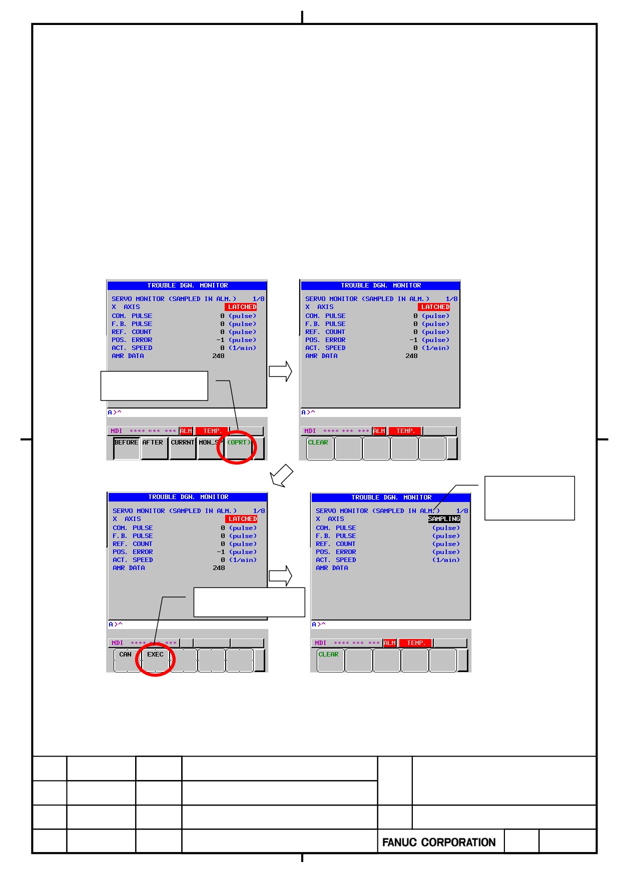
The failure diagnosis monitor has two statuses, “SAMPLING” and “LATCHED”.
The monitor is initially in the “SAMPLING” status. When an alarm occurs, it shifts to the “LATCHED” status.
When the monitor is in the “LATCHED” status, performing the “CLEAR” operation erases the data saved at alarm
occurrence and places it back to the “SAMPLING” status.
For this reason, observe the following:
・ If it is necessary to monitor data at future alarm occurrence, perform the “CLEAR” operation.
・ If it is necessary to save the statuses at past alarm occurrence, do not perform the “CLEAR” operation
Shown below is how to place the monitor back in the “SAMPLING” status by performing the “CLEAR” operation.
Press [OPRT] key
“SAMPLING”
starts blinking.
Press [EXEC] key
α+ series SERVO AMPLIFIER
TITLE
for 30+-B Start-up and
Maintenance manual
B-65285EN/03-02/04
NO.
EDT.
DATE
DESIG.
DESCRIPTION
PAGE
51 / 79
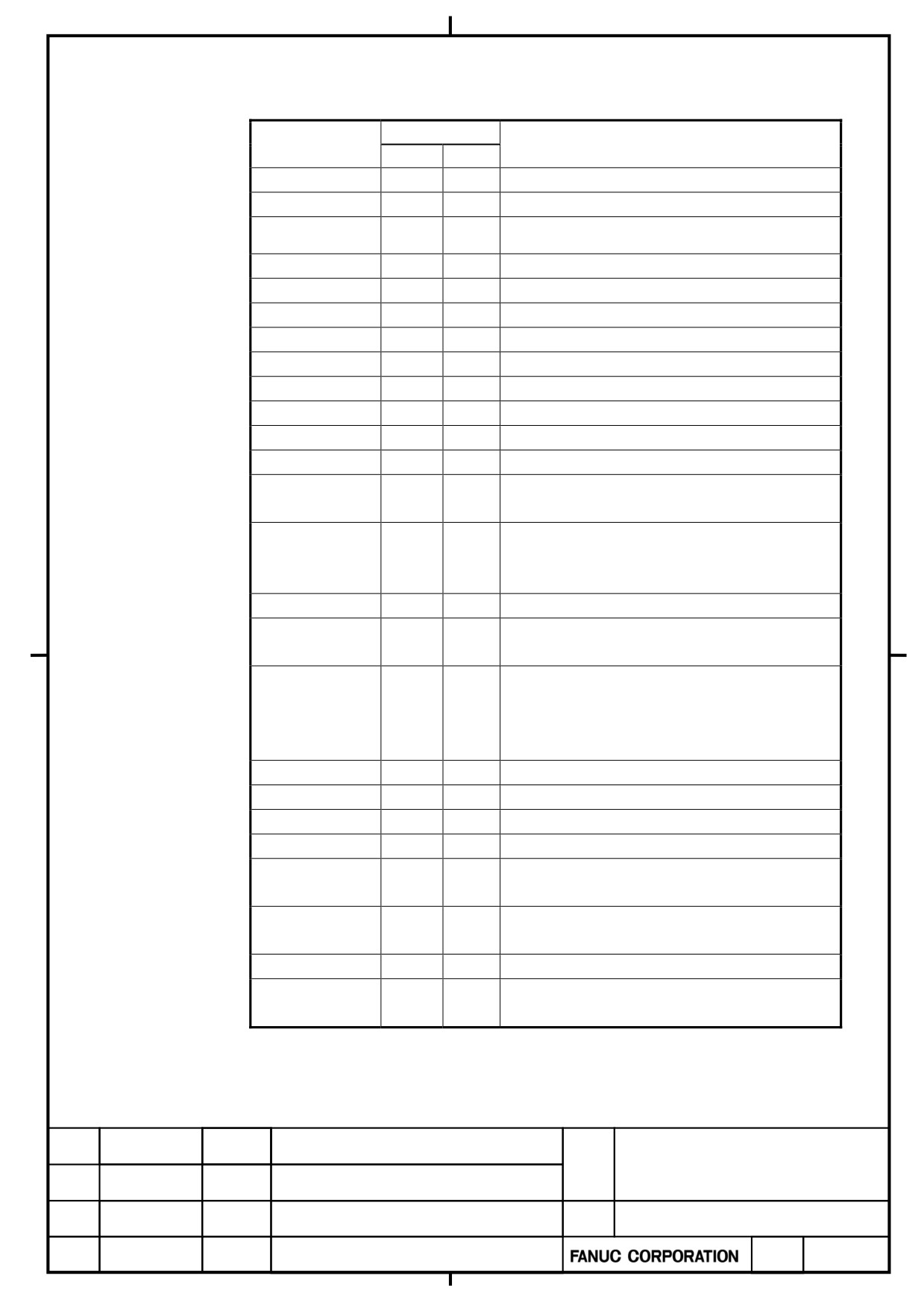
2.3.
Alarm number
2.3.1
Servo alarm
LED
Alarm No
Description
SV
PS
SV0001
Sync alignment error
SV0002
Sync excess error alarm 2
Synchronous/composite/super imposed control
SV0003
mode can’t be continued
SV0004
Excess error (G31)
SV0005
Sync excess error (MCN)
SV0006
Illegal tandem axis
SV0007
SV alarm another path (Multi AMP.)
SV0010
SV overheat
SV0011
SV motor over current(SOFT)
SV0012
4
SV drive off circuit failure
SV0013
3
SV cpu bus failure
SV0014
J
SV cpu watch dog
2
SV0015
(Blink)
SV low volt driver
b.
SV current detect error
C.
SV0016
d.
SV0017
11
SV internal serial bus failure
11
SV rom data failure
SV0018
(Blink)
b
SV motor current abnormal(Ground fault)
C
d
SV0019
(Blink)
SV0020
9
PS ground fault
SV0024
15
PS soft thermal
SV0034
24
PS hardware error
SV0035
-
NO failure
A
SV0036
(Blink)
Phase open
9
SV0037
(Blink)
Failure of SV
(OPEN)
SV0038
-
Failure of current CTL.
8
SV0039
(Blink)
Failure of SV (SHORT)
α+ series SERVO AMPLIFIER
TITLE
for 30+-B Start-up and
Maintenance manual
B-65285EN/03-02/04
NO.
EDT.
DATE
DESIG.
DESCRIPTION
PAGE
52 / 79
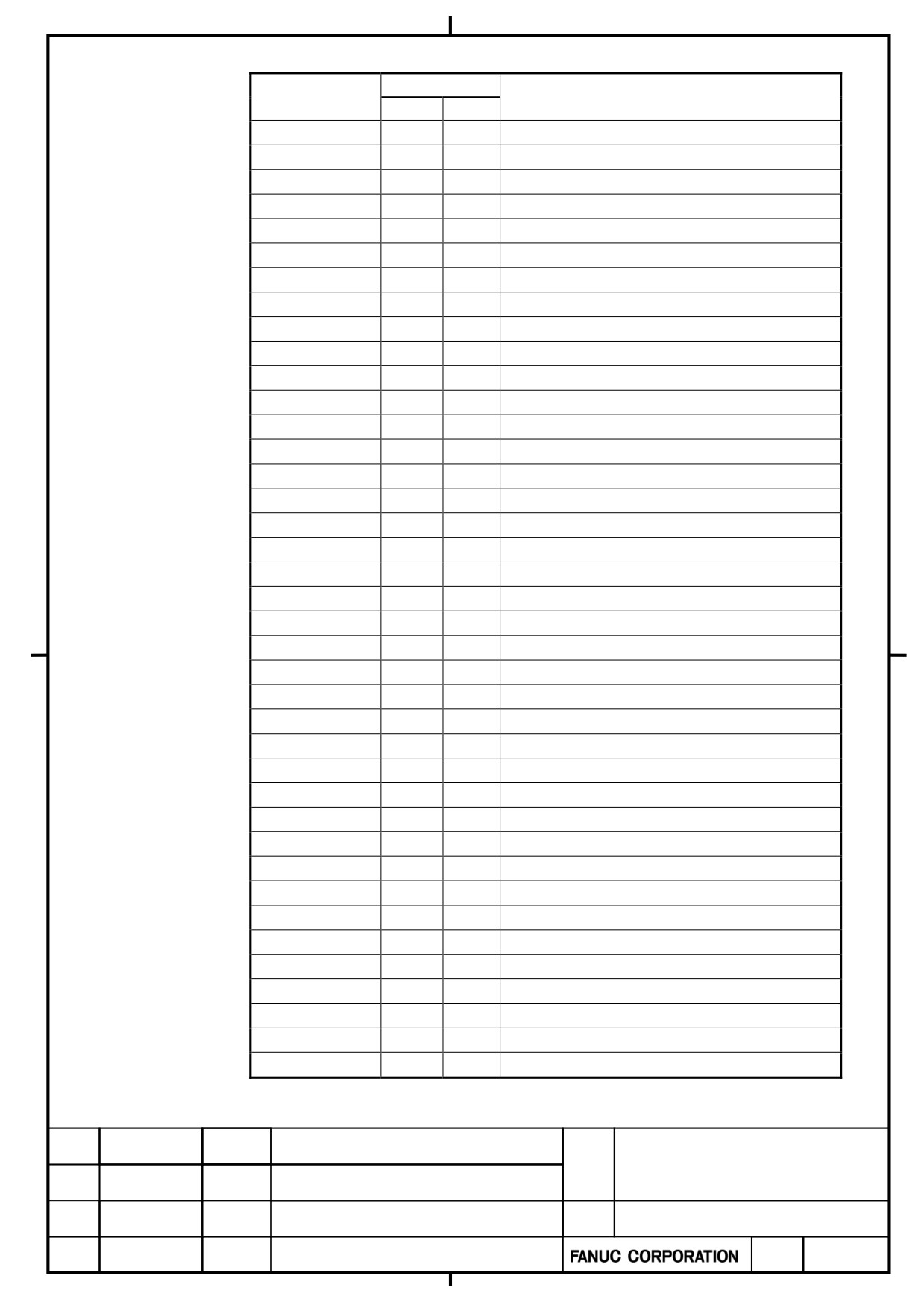
LED
Alarm No
Description
SV
PS
SV0301
APC alarm: communication error
SV0302
APC alarm: over time error
SV0303
AAPC alarm: framing error
SV0304
APC alarm: parity error
SV0305
APC alarm: pulse error
SV0306
APC alarm: over flow error
SV0307
APC alarm: movement excess error
SV0360
Abnormal checksum(INT)
SV0361
Abnormal phase data(INT)
SV0363
Abnormal clock(INT)
SV0364
Soft phase alarm(INT)
SV0365
Broken LED(INT)
SV0366
Pulse miss(INT)
SV0367
Count miss(INT)
SV0368
Serial data error(INT)
SV0369
Data trans. error(INT)
SV0380
Broken LED(EXT)
SV0381
Abnormal phase (EXT)
SV0382
Count miss(EXT)
SV0383
Pulse miss(EXT)
SV0384
Soft phase alarm(EXT)
SV0385
Serial Data error(EXT)
SV0386
Data trans. error(EXT)
SV0387
Abnormal encoder(EXT)
SV0401
Improper v_ready off
SV0403
Card/soft mismatch
SV0404
Improper v_ready on
SV0407
Excess error
SV0409
Detect abnormal Torque
SV0410
Excess error (STOP)
SV0411
Excess error (MOVING)
SV0413
LSI overflow
SV0415
Motion value overflow
SV0417
Ill dgtl servo parameter
SV0420
Sync Torque excess
SV0421
Excess error(Semi-full)
SV0422
Excess velocity in torque
SV0423
Excess error in torque
SV0430
SV motor overheat
α+ series SERVO AMPLIFIER
TITLE
for 30+-B Start-up and
Maintenance manual
B-65285EN/03-02/04
NO.
EDT.
DATE
DESIG.
DESCRIPTION
PAGE
53 / 79
LED
Alarm No
Description
SV
PS
SV0431
3
PS overload
SV0432
6
PS low volt. control
SV0433
4
PS low volt. DC link
SV0434
2
SV low volt control
SV0435
5
SV low volt DC link
SV0436
Softthermal(OVC)
SV0437
1
PS Overcurrent
b
SV abnormal current
C
SV0438
d
SV0439
7
PS over volt. DC link
SV0441
Abnormal current offset
SV0442
5
PS pre-charge failure
SV0443
2
PS internal fan failure
SV0444
1
SV internal fan failure
SV0445
Soft disconnect alarm
SV0446
Hard disconnect alarm
SV0447
Hard disconnect(EXT)
SV0448
Unmatched feedback alarm
8.
SV IPM alarm
9.
SV0449
A.
SV0453
SPC soft disconnect alarm
SV0454
Illegal rotor pos detect
SV0456
Illegal current loop
SV0458
Current loop error
SV0459
Hi HRV setting error
SV0460
FSSB disconnect
SV0462
Send CNC data failed
SV0463
Send slave data failed
SV0465
Read ID data failed
SV0466
Motor/Amp. Combination
SV0468
Hi HRV setting error(AMP)
SV0474
Excess error(STOP:SV )
SV0475
Excess error(MOVE:SV)
SV0476
Illegal Speed cmd.(SV )
SV0477
Illegal machine pos.(SV)
SV0478
Illegal axis data(SV)
α+ series SERVO AMPLIFIER
TITLE
for 30+-B Start-up and
Maintenance manual
B-65285EN/03-02/04
NO.
EDT.
DATE
DESIG.
DESCRIPTION
PAGE
54 / 79
LED
Alarm No
Description
SV
PS
SV0481
Safety param error(SV)
SV0484
Safety function error(SV)
SV0488
Self test over time
SV0489
Safety param error(CNC)
SV0490
Safety function error(CNC)
SV0494
Illegal speed cmd.(CNC)
SV0496
Illegal axis data(CNC)
SV0498
Axis number not set(CNC)
SV0600
8
SV DC link over current
SV0601
F
SV external fan failure
SV0602
6
SV overheat
8.
SV IPM alarm(OH)
9.
SV0603
A.
SV0604
P
AMP communication error
SV0606
10
PS external fan failure
SV0607
14
PS improper Input power
SV0646
Abnormal analog signal(EXT)
SV0652
Temp.error
SV0654
7
DB Relay failure
SV1025
V_ready on (Initializing )
SV1026
Illegal axis arrange
SV1055
Illegal tandem axis
SV1067
FSSB:configuration error(SOFT)
SV1068
Dual check safety alarm
SV1069
Excess error(Servo off:CNC)
SV1070
Excess error(Servo off:SV)
SV1071
Excess error(Move:CNC)
SV1072
Excess error(Stop:CNC)
SV1100
S-comp. value overflow
SV5134
FSSB:Open ready time out
SV5136
FSSB:Number of AMP. is insufficient
SV5137
FSSB:Configuration error
SV5139
FSSB:Error
SV5197
FSSB:Open time out
SV5311
FSSB:Illegal connection
α+ series SERVO AMPLIFIER
TITLE
for 30+-B Start-up and
Maintenance manual
B-65285EN/03-02/04
NO.
EDT.
DATE
DESIG.
DESCRIPTION
PAGE
55 / 79
2.3.2
Spindle Alarm
LED
Alarm No
Description
SP
PS
SP9001
01
Motor overheat
SP9002
02
Excessive speed deviation
SP9003
03
DC link fuse blown
SP9004
14
Open phase in the converter main power supply
SP9006
06
Temperature sensor disconnected
SP9007
07
Excessive speed
SP9009
09
Main circuit overload/IPM overheat
SP9010
10
Low voltage input power
SP9011
07
Converter: DC link overvoltage
SP9012
12
DC link overcurrent/IPM alarm
13
CPU Data memory fault
SP9014
14
No ID number
SP9015
15
Output switching/spindle switching alarm
SP9016
16
RAM Error
SP9017
17
ID number parity error
18
Program sum check error
19
Excessive offset of the phase U current detection
SP9019
circuit
20
Excessive offset of the phase V current detection
SP9020
circuit
SP9021
21
Position sensor polarity setting incorrect
SP9022
22
Spindle Amplifier overload current
24
Serial transfer data error
SP9027
27
Position coder disconnected
SP9029
29
Short-period overload
SP9030
01
Overcurrent in the converter input circuit
SP9031
31
Motor lock alarm
SP9032
32
Serial communication LSI RAM error
SP9033
05
Converter: DC link precharge failure
SP9034
34
Parameter data out of the specifiable range
SP9036
36
Error counter overflow
SP9037
37
Speed detector parameter error
SP9041
41
Position coder one-rotation signal detection error
SP9042
42
Position coder one-rotation signal not detected
SP9043
43
Disconnect position corder signal for differential speed
46
Position sensor one-rotation signal detection error
SP9046
during thread cutting
SP9047
47
Position coder signal error
α+ series SERVO AMPLIFIER
TITLE
for 30+-B Start-up and
Maintenance manual
B-65285EN/03-02/04
NO.
EDT.
DATE
DESIG.
DESCRIPTION
PAGE
56 / 79
LED
Alarm No
Description
SP
PS
SP9049
49
Differential speed is over value
50
Excessive speed command calculation value during
SP9050
spindle synchronization
SP9051
04
Converter: DC link undervoltage
SP9052
52
ITP signal error I
SP9053
53
ITP signal error II
SP9054
54
Current overload alarm
SP9055
55
Abnormal switching status of power leads
SP9056
56
Internal cooling fan stopped
SP9058
03
Converter: main circuit overload
SP9059
02
Converter: cooling fan stopped
SP9061
61
Excess of error between semi-closed and full-closed
65
Move distance is too long when Magnetic pole
SP9065
confirmed
SP9066
66
Communication alarm between spindle amplifiers
SP9067
67
FSC/EGB command error
SP9069
69
Safety speed exceeded
SP9070
70
Abnormal axis data
SP9071
71
Abnormal safety parameter
SP9072
72
Motor speed mismatch
SP9073
73
Motor sensor disconnected
SP9074
74
CPU test alarm
SP9075
75
CRC test alarm
SP9076
76
Safety function not executed
SP9077
77
Axis number mismatch
SP9078
78
Safety parameter mismatch
SP9079
79
Abnormal initial test operation
SP9080
80
Alarm at the other spindle amplifier
SP9081
81
Motor sensor one-rotation signal detection error
SP9082
82
Motor sensor one-rotation signal not detected
SP9083
83
Motor sensor signal error
SP9084
84
Spindle sensor disconnected
SP9085
85
Spindle sensor one-rotation signal detection error
SP9086
86
Spindle sensor one-rotation signal not detected
SP9087
87
Spindle sensor signal error
SP9088
88
Cooling fan stopped of the radiator
SP9089
89
Sub module SM error
SP9090
90
Unexpected rotation
SP9091
91
Pole position count miss
α+ series SERVO AMPLIFIER
TITLE
for 30+-B Start-up and
Maintenance manual
B-65285EN/03-02/04
NO.
EDT.
DATE
DESIG.
DESCRIPTION
PAGE
57 / 79
LED
Alarm No
Description
SP
PS
SP9092
92
Over speed to velocity command
A
Program ROM error
A1
Program ROM error
A2
Program ROM error
SP9110
b0
Communication error between amplifiers
SP9111
06
Converter: control power supply low voltage
SP9113
10
PS external fan failure
SP9114
b4
PS control axis error 1
SP9115
b5
PS control axis error 2
SP9120
C0
Communication data alarm
SP9121
C1
Communication data alarm
SP9122
C2
Communication data alarm
SP9123
C3
Spindle switching circuit error
SP9124
C4
Learning control rotation command error
SP9125
C5
Learning control compensation order error
SP9127
C7
Learning control period error
SP9128
C8
Spindle synchronous control velocity error excess
SP9129
C9
Spindle synchronous control position error excess
SP9130
d0
Torque tandem polarity error
SP9131
d1
Spindle tuning function alarm
SP9132
d2
Serial sensor data error
SP9133
d3
Serial sensor transfer error
SP9134
d4
Serial sensor soft phase error
SP9137
d7
SP device communication error
SP9138
d8
Current limit setting error
SP9139
d9
Serial sensor pulse miss
SP9140
E0
Serial sensor count miss
SP9141
E1
Serial sensor no 1 rotation signal
SP9142
E2
Serial sensor abnormal
SP9143
E3
Cs high speed change command error
SP9144
E4
Current detect circuit error
SP9145
E5
Low voltage for driver circuit
SP9147
E7
Spindle ground fault
SP9148
E8
Axis number not set
SP9153
F3
SP not failure
SP9154
F4
Phase open
SP9155
F5
Failure of SP (OPEN)
SP9156
F6
Current control failure
α+ series SERVO AMPLIFIER
TITLE
for 30+-B Start-up and
Maintenance manual
B-65285EN/03-02/04
NO.
EDT.
DATE
DESIG.
DESCRIPTION
PAGE
58 / 79
LED
Alarm No
Description
SP
PS
SP9157
F7
Failure of SP (SHORT)
SP9160
G0
Spindle thermistor disconnect
SP9161
G1
Motor power line short-circuit
UU
FSSB master port disconnect
LL
FSSB slave port disconnect
SP0756
Axes data error
SP9200
9
Power supply ground fault
SP9204
15
PS soft thermal
SP9212
24
PS hardware error
α+ series SERVO AMPLIFIER
TITLE
for 30+-B Start-up and
Maintenance manual
B-65285EN/03-02/04
NO.
EDT.
DATE
DESIG.
DESCRIPTION
PAGE
59 / 79