FANUC AC Servo Amplifiers βi Series. Description Manual (B-65322EN/02) - page 9
B-65322EN/02
I/O Link
9.TOTAL CONNECTION DIAGRAM
9.2.16 Connection to External Pulse Generator
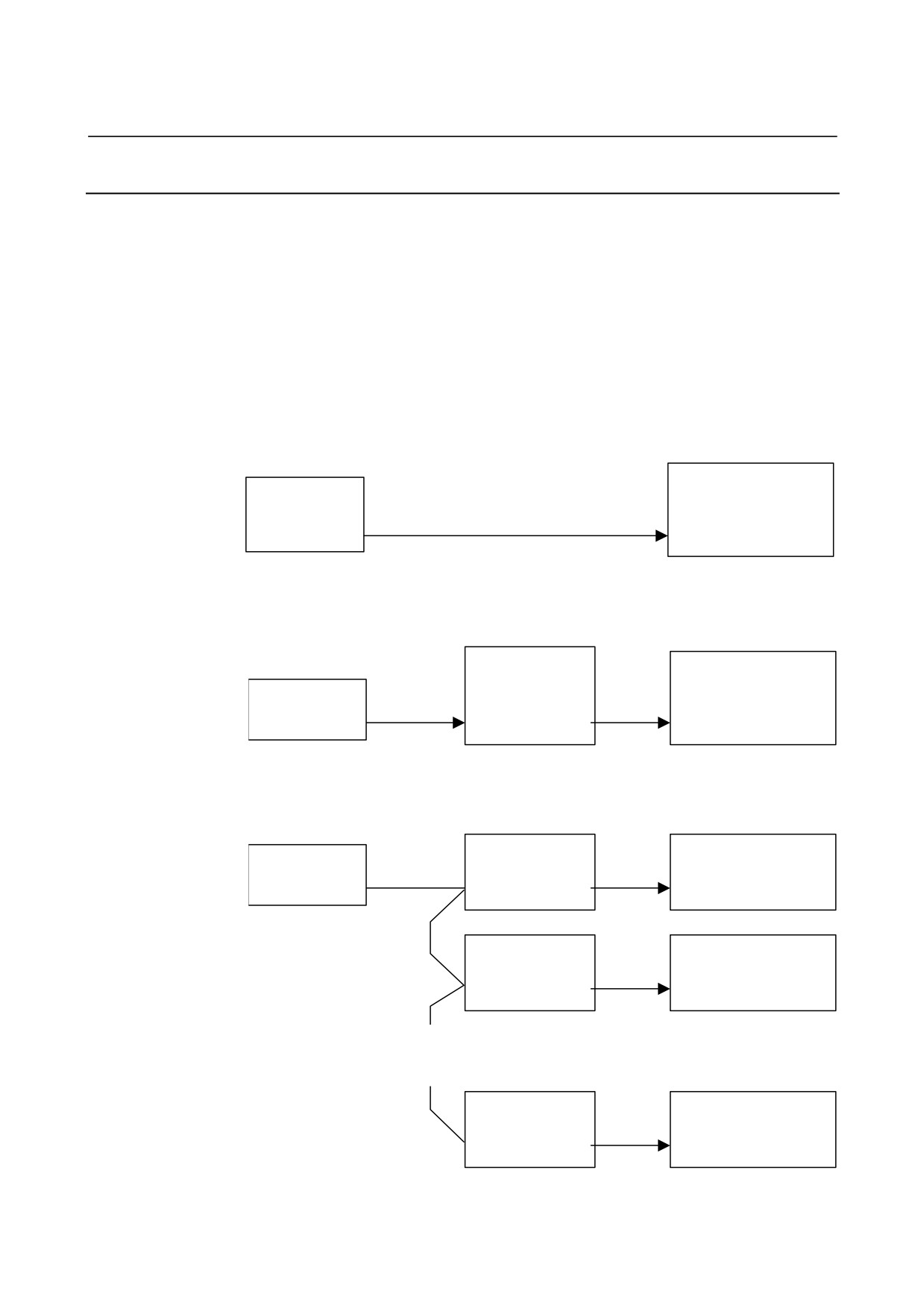
The βi SVM can operate according to the pulse input from the outside.
As the external pulse generator, a differential type A/B phase pulse
generator that satisfies specifications or FANUC's manual pulse
generator may be selected. When selecting the manual pulse
generator, you need a manual pulse generator adapter
(A06B-6093-D001).
One manual pulse generator can be connected to up to six βi SVM
units. In this case, one manual pulse generator adapter is required
per βi SVM unit.
When a differential type A/B phase pulse generator is used
βi SVM
External pulse
generator
K22
(differential
output)
JA34
When FANUC's manual pulse generator is used (connected to βi SVM on a
one-to-one basis)
Manual pulse
βi SVM
generator
Manual pulse
adapter
K23
K24
generator
JA54
JA55
JA34
When FANUC's manual pulse generator is used (connected to more than
one βi SVM)
Manual pulse
βi SVM#1
Manual pulse
K25
generator adapter
K24
generator
#1
JA34
JA54
JA55
K25
Manual pulse
βi SVM#2
generator adapter
K24
#2
JA34
JA54
JA55
K25
:
:
:
:
:
:
:
:
:
K25
Manual pulse
βi SVM#6
generator adapter
K24
#6
JA34
JA54
JA55
- 229 -
9.TOTAL CONNECTION DIAGRAM
I/O Link
B-65322EN/02
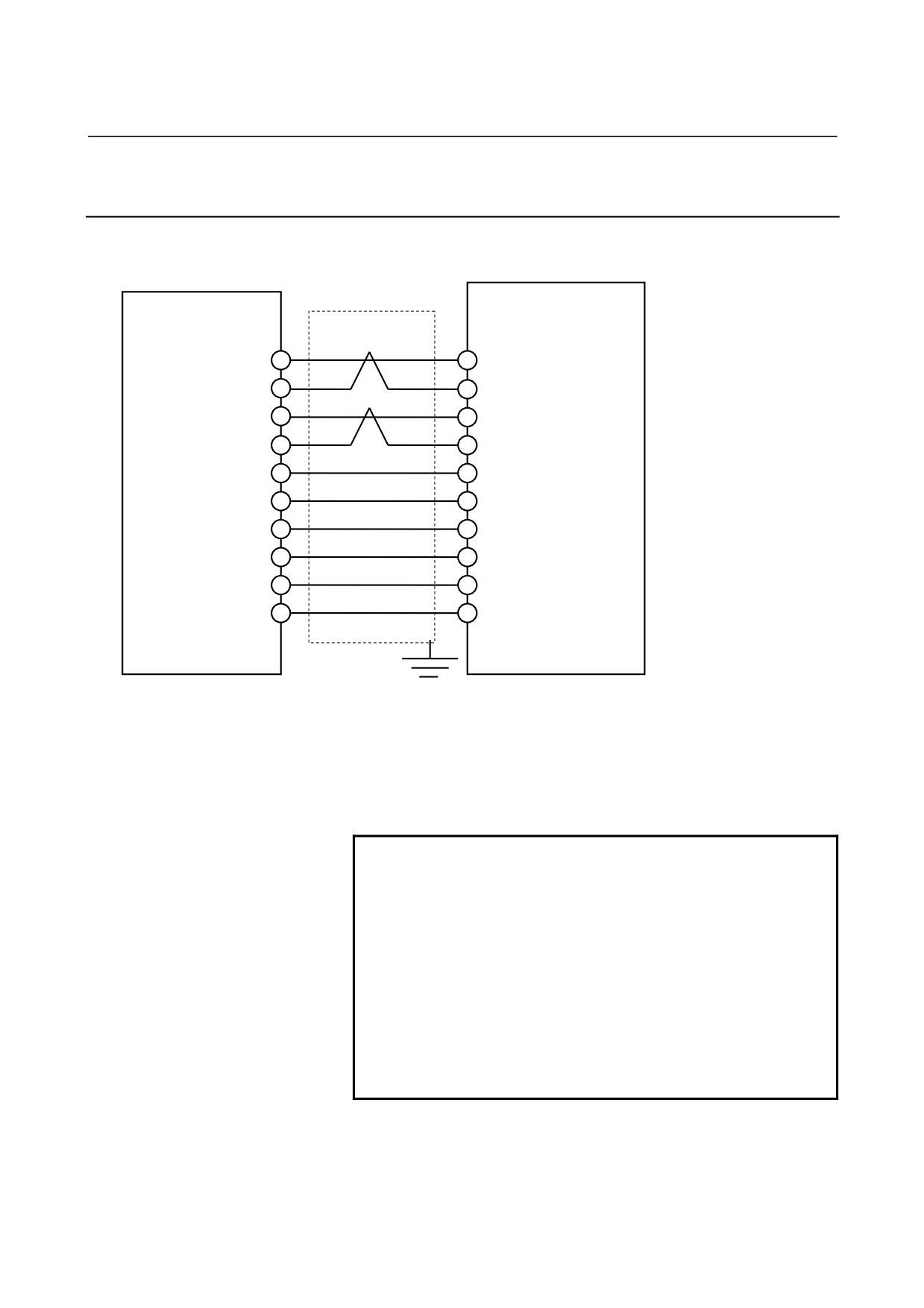
9.2.16.1 Connection when differential type A/B phase pulse generator
is used
Details of cable K22
K22
External pulse generator
βi SVM
(differential output)
JA34
PA
(1) PA
*PA
(2) *PA
PB
(3) PB
*PB
(4) *PB
+5V
(9) +5V
+5V
(18) +5V
+5V
(20) +5V
0V
(12) 0V
0V
(14) 0V
0V
(16) 0V
Connector: FI40-2015S (Hirose Electric Co., Ltd.)
Case: FI-20-CV (Hirose Electric Co., Ltd.)
Cable specification: Conductor 20/0.18 × 6, 7/0.18 × 3 pairs
Recommended cable:
A66L-0001-0286 (#20AWG × 6 + #24AWG × 6 + #24AWG × 3 pairs)
NOTE
1 Power can be supplied from the βi SVM to the
equipment if the equipment operates on +5 V and
0.35 A maximum.
In this case, pay attention to the power supply
voltage drop due to cable resistance.
2 Be sure to use twisted pairs to connect the PA and
*PA signals and the PB and *PB signals in pairs.
3 Except the pins indicated in the above figure, leave
pins open. Never connect unused conductors of
the cable to these pins.
4 Maximum cable length:
50 m
- 230 -
B-65322EN/02
I/O Link
9.TOTAL CONNECTION DIAGRAM
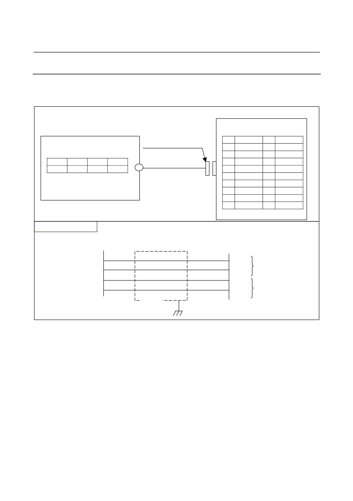
9.2.16.2 Connection when FANUC's manual pulse generator is used
Details of cable K23
Cable K23 is a signal cable used to connect the manual
pulse
generator and adapter (JA54).
Manual pulse generator adapter
JA54
Manual pulse generator
Connector: FI40-2015S
(PCR-EV20MDT)
Case: FI-20-CV
1
HA1
11
(M3 screw terminal)
2
HB1
12
0V
3
(HA2)
13
+5V
0V
A
B
4
(HB2)
14
0V
K23
+5V
0V
HA1
HB1
5
15
6
16
0V
7
17
8
18
+5V
9
+5V
19
10
20
+5V
Cable connection (K23)
Manual pulse generator
JA54
A
1
HA1
HA1
B
2
#24AWG
HB1
HB1
+5V
9,18,20
+5V
+5V
0V
12,14,16
#20AWG
0V
0V
Shield
Recommended cable:
A66L-0001-0286 (#20AWG × 6 + #24AWG × 3 pairs)
Recommended connector (JA54 side)
Connector: FI40-2015S (Hirose Electric Co., Ltd.)
Case:
FI-20-CV (Hirose Electric Co., Ltd.)
Recommended cable:
A02B-0259-K821 (7m) Change the connector name before use.
Although the maximum cable length is 50 m, the length is further
limited because of the power supply voltage drop as follows:
Limitation due to power supply voltage drop
Suppress the power supply voltage drop due to the cable resistance to
0.2 V or less (the sum of the voltage drop of both the 0V and 5V lines).
Perform calculation assuming that the power supply current of the
manual pulse generator is 0.1 A.
In the calculations, the cable length must include the cable length of
K24.
- 231 -
9.TOTAL CONNECTION DIAGRAM
I/O Link
B-65322EN/02
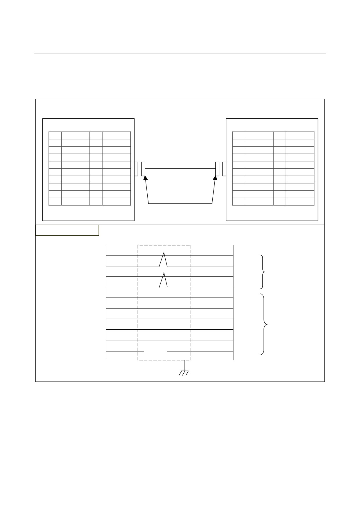
Details of cable K24
Cable K24 is a signal cable used to connect the manual pulse
generator adapter (JA55) and the βi SVM (JA34).
βi SVM
Manual pulse generator adapter
JA55
JA34
(PCR-EV20MDT)
(PCR-EV20MDT)
1
PA
11
1
PA
11
2
*PA
12
0V
2
*PA
12
0V
3
PB
13
3
PB
13
4
*PB
14
0V
4
*PB
14
0V
5
15
K24
5
15
6
16
0V
6
16
0V
7
17
7
17
Connector: FI40-2015S
8
18
+5V
8
18
+5V
9
+5V
19
Case: FI-20-CV
9
+5V
19
10
20
+5V
10
20
+5V
Cable connection (K24)
JA55
JA34
1
1
PA
PA
2
2
*PA
*PA
3
3
#24AWG
PB
PB
4
4
*PB
*PB
9
9
+5V
+5V
18
18
+5V
+5V
20
20
+5V
+5V
#20AWG
12
12
0V
0V
14
14
0V
0V
16
16
0V
0V
Shield
Recommended cable: A66L-0001-0286 (#20AWG × 6 + #24AWG
× 3 pairs)
Recommended connector:
Connector: FI40-2015S (Hirose Electric Co., Ltd.)
Case:
FI-20-CV (Hirose Electric Co., Ltd.)
The maximum cable length is 5 m.
- 232 -
B-65322EN/02
I/O Link
9.TOTAL CONNECTION DIAGRAM
Details of cable K25
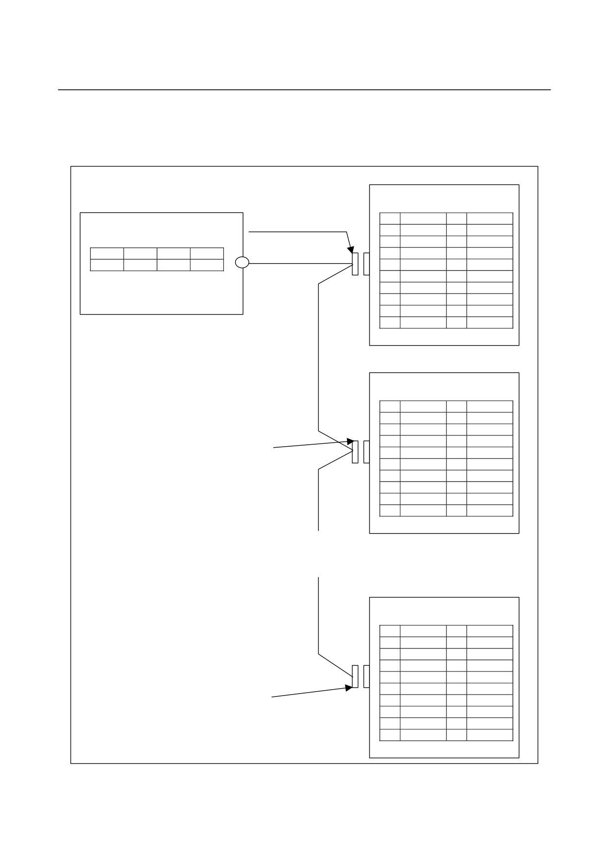
Cable K25 is a signal cable used to connect the manual pulse
generator and more than one manual pulse generator adapter (JA54).
Manual pulse generator adapter #1
JA54
Manual pulse generator
Connector: FI40-2015S
(PCR-EV20MDT)
Case: FI-20-CV
1
HA1
11
(M3 screw terminal)
2
HB1
12
0V
3
HA2
13
+5V
0V
A
B
4
HB2
14
0V
K25
+5V
0V
HA1
HB1
5
15
6
16
0V
7
17
8
18
+5V
9
+5V
19
10
20
+5V
K25
Manual pulse generator adapter #2
JA54
(PCR-EV20MDT)
1
HA1
11
2
HB1
12
0V
3
HA2
13
Connector: FI40-2015S
4
HB2
14
0V
Case: FI-20-CV
5
15
6
16
0V
7
17
8
18
(+5V)
K25
9
(+5V)
19
10
20
(+5V)
:
:
:
:
Manual pulse generator adapter #6
JA54
(PCR-EV20MDT)
K25
1
HA1
11
2
HB1
12
0V
3
HA2
13
4
HB2
14
0V
5
15
Connector: FI40-2015S
6
16
0V
Case: FI-20-CV
7
17
8
18
(+5V)
9
(+5V)
19
10
20
(+5V)
- 233 -
9.TOTAL CONNECTION DIAGRAM
I/O Link
B-65322EN/02
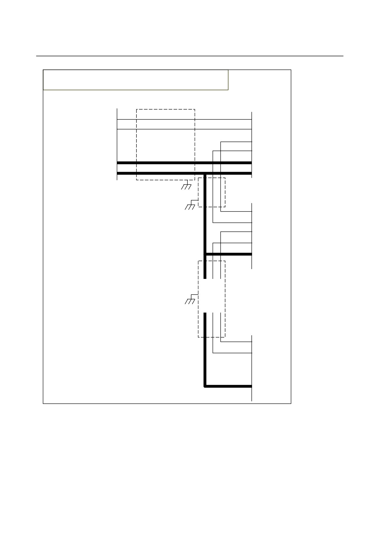
Cable connection (K25)
The bold lines indicate that three conductors are used for connection.
Manual pulse generator
JA54
A
1
HA1
HA1
B
2
HB1
HB1
3
HA2
4
HB2
+5V
9,18,20
+5V
+5V
0V
12,14,16
0V
0V
JA54
1
HA1
2
HB1
3
HA2
4
HB2
12,14,16
0V
:
:
:
:
JA54
1
HA1
2
HB1
3
HA2
4
HB2
12,14,16
0V
- 234 -
B-65322EN/02
I/O Link
9.TOTAL CONNECTION DIAGRAM
Manual pulse generator adapter
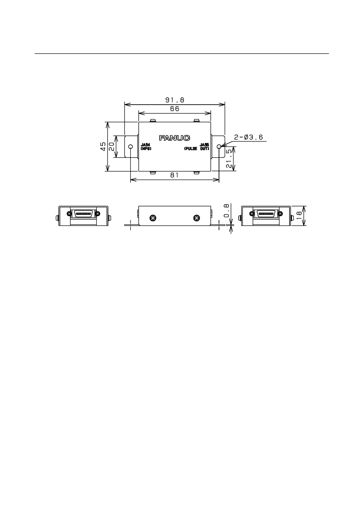
- Dimensions
Weight: Approximately 100 g
- Installation condition
Because the manual pulse generator adapter does not have a sealed
structure, it must be installed in a sealed cabinet similar to the cabinet
of the βi SVM.
The manual pulse generator adapter has two 3.6-diameter holes. Use
these holes to secure the adapter.
Because being lightweight, the manual pulse generator adapter need
not secured with screws. However, be careful not to allow the
adapter to touch other electrical circuits to cause short-circuit.
Ground the case by using the case mounting screw of the manual
pulse generator adapter.
- 235 -
9.TOTAL CONNECTION DIAGRAM
I/O Link
B-65322EN/02
- Operation conditions
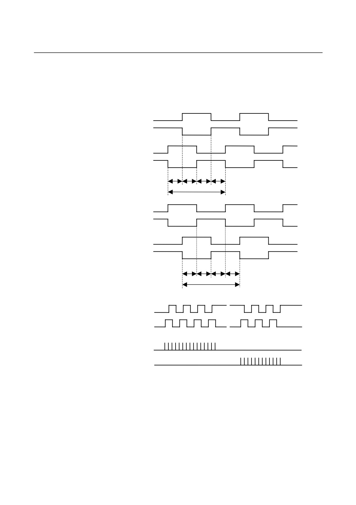
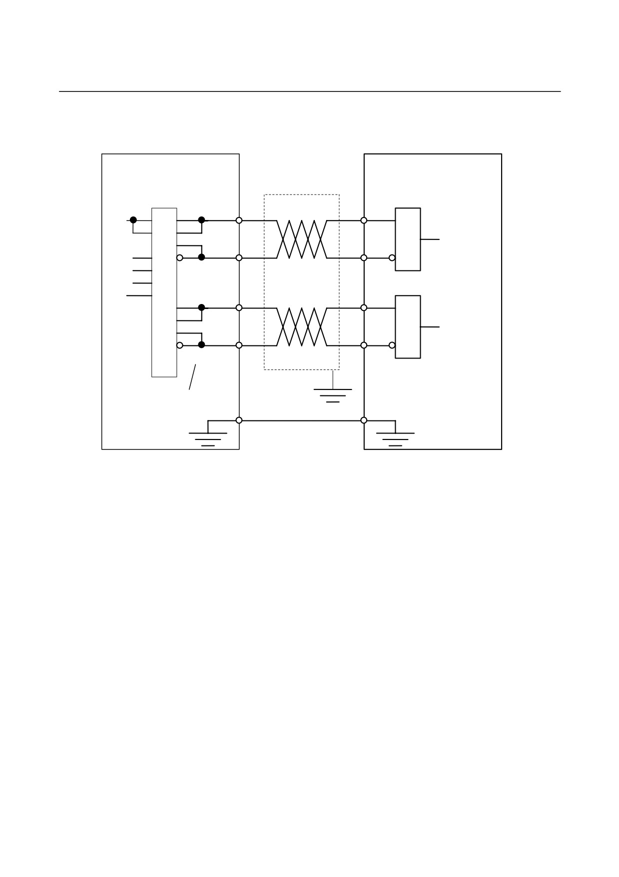
The maximum allowable frequency of the input signals is 100 kHz.
The βi SVM multiplies input pulses by four to obtain move commands.
Therefore, up to 400 kpps is specified as a move command.
1)
Positive direction move command pulse
PA
*PA
PB
*PB
Tp Tp Tp Tp
Tcyc
2)
Negative direction move command pulse
PA
*PA
PB
*PB
Tp Tp
Tp
Tp
Tp:
1.2µsec or more
Tcyc:
10µsec or more
Tcyc
3)
Sequence
PA
External input
pulse
PB
βi SVM
+ pulse
internal input
- pulse
- 236 -
B-65322EN/02
I/O Link
9.TOTAL CONNECTION DIAGRAM
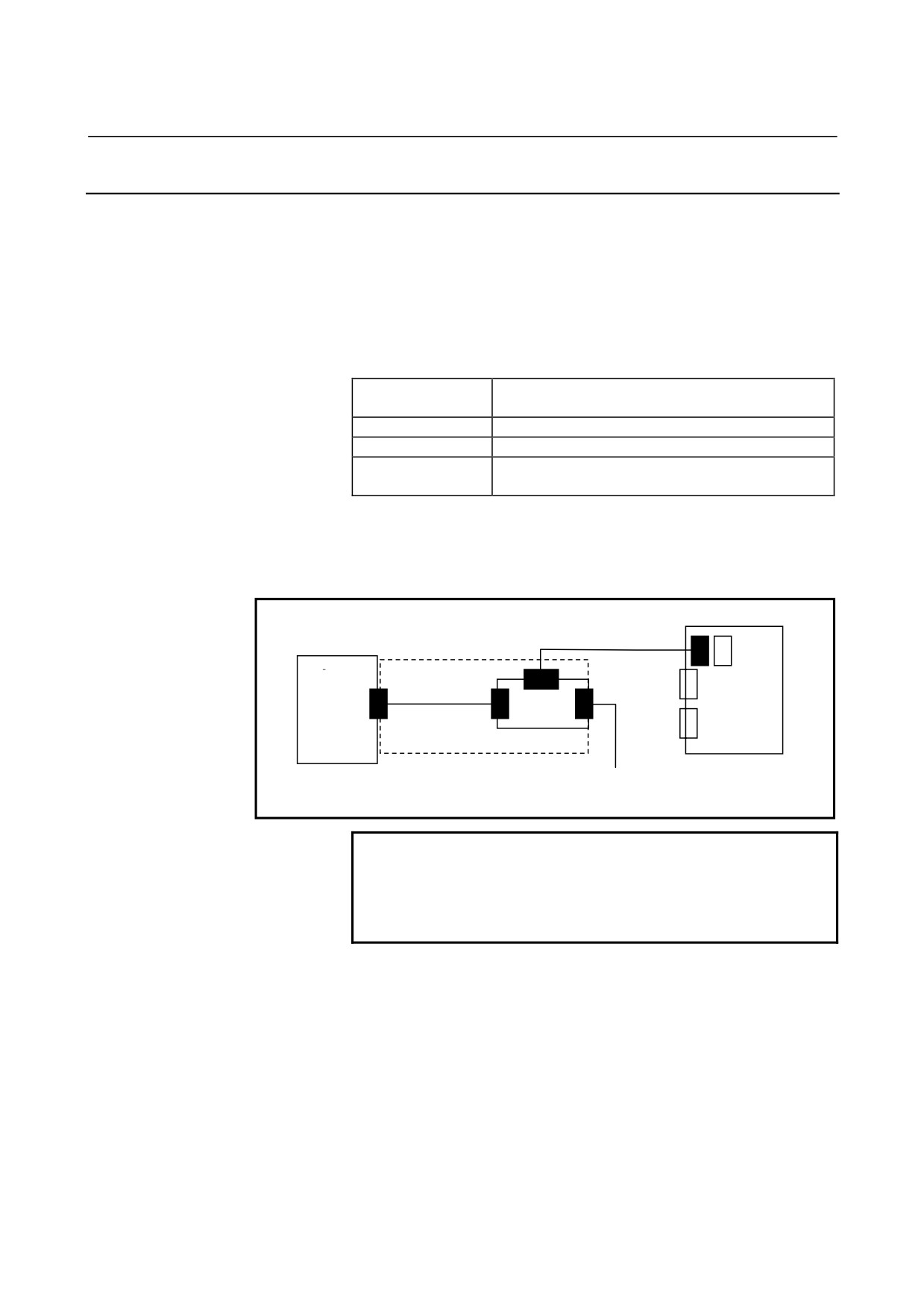
- Recommended circuit example
External pulse generator
βi SVM
SN75113 or equivalent
Receiver circuit
1
PA
5
4,3
PA
6
2
*PA
7
9
1,2
10
11
12,13
3
PB
4
*PB
14,15
Numbers denote pin
numbers of SN75113
12,14,16
- 237 -
9.TOTAL CONNECTION DIAGRAM
I/O Link
B-65322EN/02
9.2.17 Connection to Servo Check Board
The servo check board converts digital values used for control in the
digital servo system into analog voltages to allow observation with
instruments such as an oscilloscope.
Ordering specification
A cable with a reverse connection prevention feature and a servo
check board adapter are required to connect the servo check board to
the βi SVM.
Ordering
Name
specification
A06B-6057-H630
Servo check board
A06B-6050-K871
Cable with reverse connection prevention feature
Servo check board adapter
A06B-6093-K021
(adapter board and cable, both dedicated to βi SVM)
Connection
Before installing and removing the servo check board, turn off the
power to the βi SVM.
Cable with reverse
insertion prevention
CNI1
feature
Adapter board + cable
A06B-6050-K871
A06B-6093-K021
βi SVM
TEST
JN1
JD1A
JD1A
K20
Servo check board
To the stage that follows the I/O Link
A06B-6057-H630
NOTE
The servo check board adapter and the servo
check board may be connected only when
adjustments are made. Never start operation
while they are left connected.
- 238 -
B-65322EN/02
I/O Link
10.HEAT DISSIPATION
10
HEAT DISSIPATION
See Chapter 10 “HEAT DISSIPATION” in Part I.
- 239 -
B-65322EN/02
APPENDIX A.CONNECTING THE REACTOR AND LINE FILETER
A
CONNECTING THE REACTOR AND LINE
FILETER
- 243 -
A.CONNECTING THE REACTOR AND LINE FILETER APPENDIX
B-65322EN/02
A.1 OVERVIEW
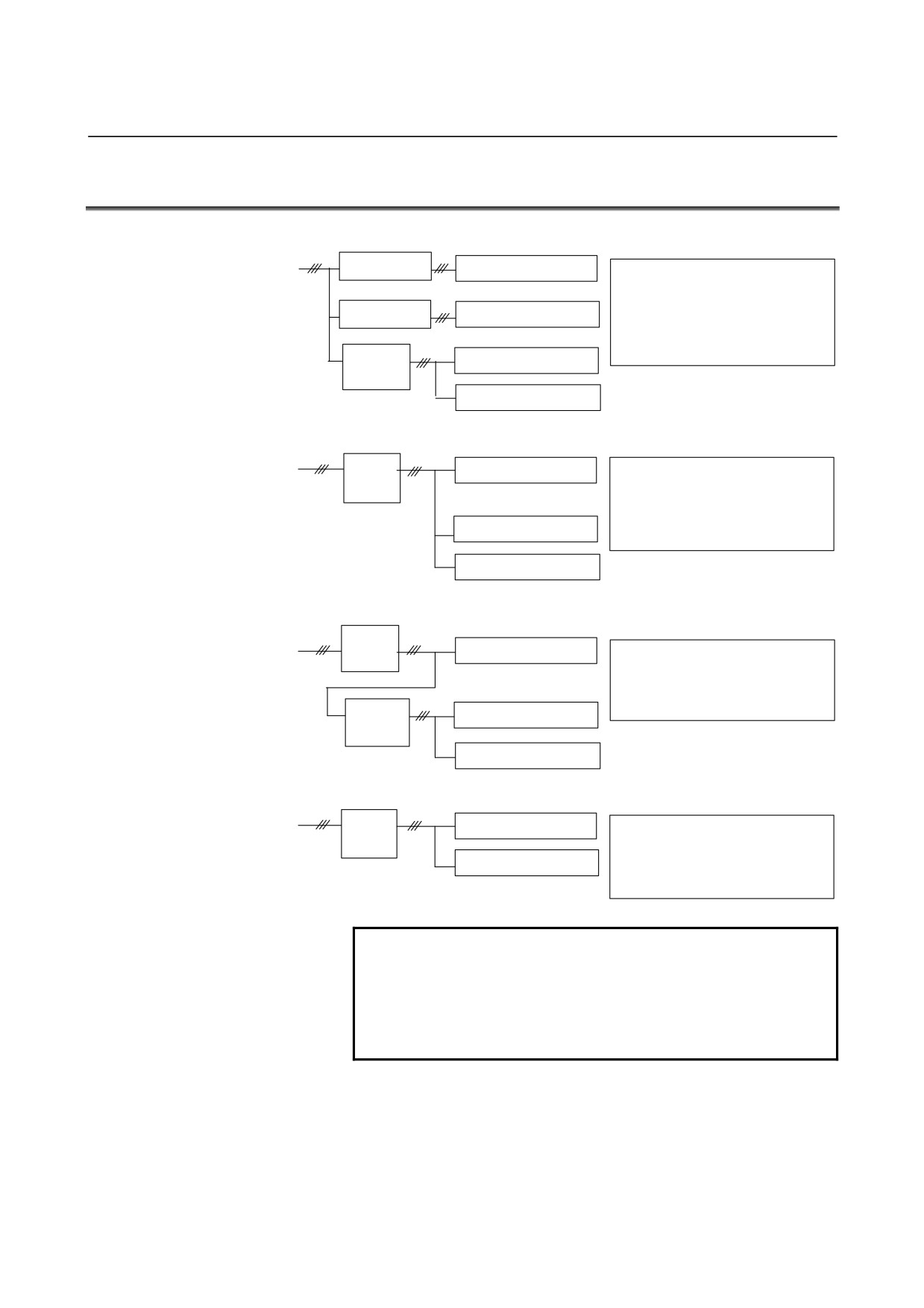
Below are an correct example and incorrect examples of connection of
the reactor for the power supply regenerative amplifier and the line
filter for the resistive discharge amplifier.
- 244 -
B-65322EN/02
APPENDIX A.CONNECTING THE REACTOR AND LINE FILETER
A.2
CONNECTION EXAMPLES
Correct connection
Reactor (Note 3)
Power supply regenerative
• One power supply regenerative amplifier is
amplifier (Note 1)
connected to one rector.
• The line filter is connected from the primary
Reactor (Note 3)
Power supply regenerative
side of the rector.
amplifier (Note 1)
• More than one resistance regenerative
amplifier can be connected to the line filter.
(The current rating of the line filter must not
Line filter
Resistance regenerative
be exceeded, however.)
(Note 4)
amplifier (Note 2)
Resistance regenerative
amplifier (Note 2)
Incorrect connection (1)
Reactor
Power supply regenerative
• The resistance regenerative amplifier is
(Note 3)
amplifier (Note 1)
connected to the secondary side of the
rector.
The resistance regenerative amplifier may be
damaged.
Resistance regenerative
The power supply regenerative amplifier may
amplifier (Note 2)
malfunction.
Resistance regenerative
amplifier (Note 2)
Incorrect connection (2)
Reactor
(Note 3)
Power supply regenerative
• The line filter is connected from the
amplifier (Note 1)
secondary side of the rector.
The resistance regenerative amplifier may be
damaged.
The power supply regenerative amplifier may
Line filter
Resistance regenerative
malfunction.
(Note 4)
amplifier (Note 2)
Resistance regenerative
amplifier (Note 2)
Incorrect connection (3)
Reactor
Power supply regenerative
• More than one power supply regenerative
(Note 3)
amplifier (Note 1)
amplifier is connected to one reactor.
One power supply regenerative amplifier may
Power supply regenerative
be damaged.
amplifier (Note 1)
The other power supply regenerative amplifier
may malfunction.
NOTE
Any devices must not be connected between the
rector and power supply regenerative amplifier.
Otherwise, the connected device may be damaged
and the power supply regenerative amplifier may
malfunction.
- 245 -
A.CONNECTING THE REACTOR AND LINE FILETER APPENDIX
B-65322EN/02
(1)
Power supply regenerative amplifier
α series PSM
A06B-6077-HXXX, A06B-6087-HXXX
αi series PSM
A06B-6110-HXXX
βi series SVPM
A06B-6134-HXXX
Others
(2)
Resistance regenerative amplifier
α series PSMR
A06B-6081-HXXX
αi series PSMR
A06B-6115-HXXX
α series SVU
A06B-6089-HXXX
α series SVUC
A06B-6090-HXXX
β series SVU
A06B-6093-HXXX
βi series SVM
A06B-6130-HXXX
A06B-6132-HXXX
Others
(3)
Reactor
A81L-0001-0133
A81L-0001-0147
A81L-0001-0150
A81L-0001-0122
A81L-0001-0123
A81L-0001-0120
A81L-0001-0124
A81L-0001-0155
A81L-0001-0156
A81L-0001-0157
A81L-0001-0158
A81L-0001-0159
A81L-0001-0160
Others
(4)
Line filter
A81L-0001-0083/3C
A81L-0001-0101/C
A81L-0001-0102
Others
- 246 -
FANUC SERVO AMPLIFIER βi series DESCRIPTIONS
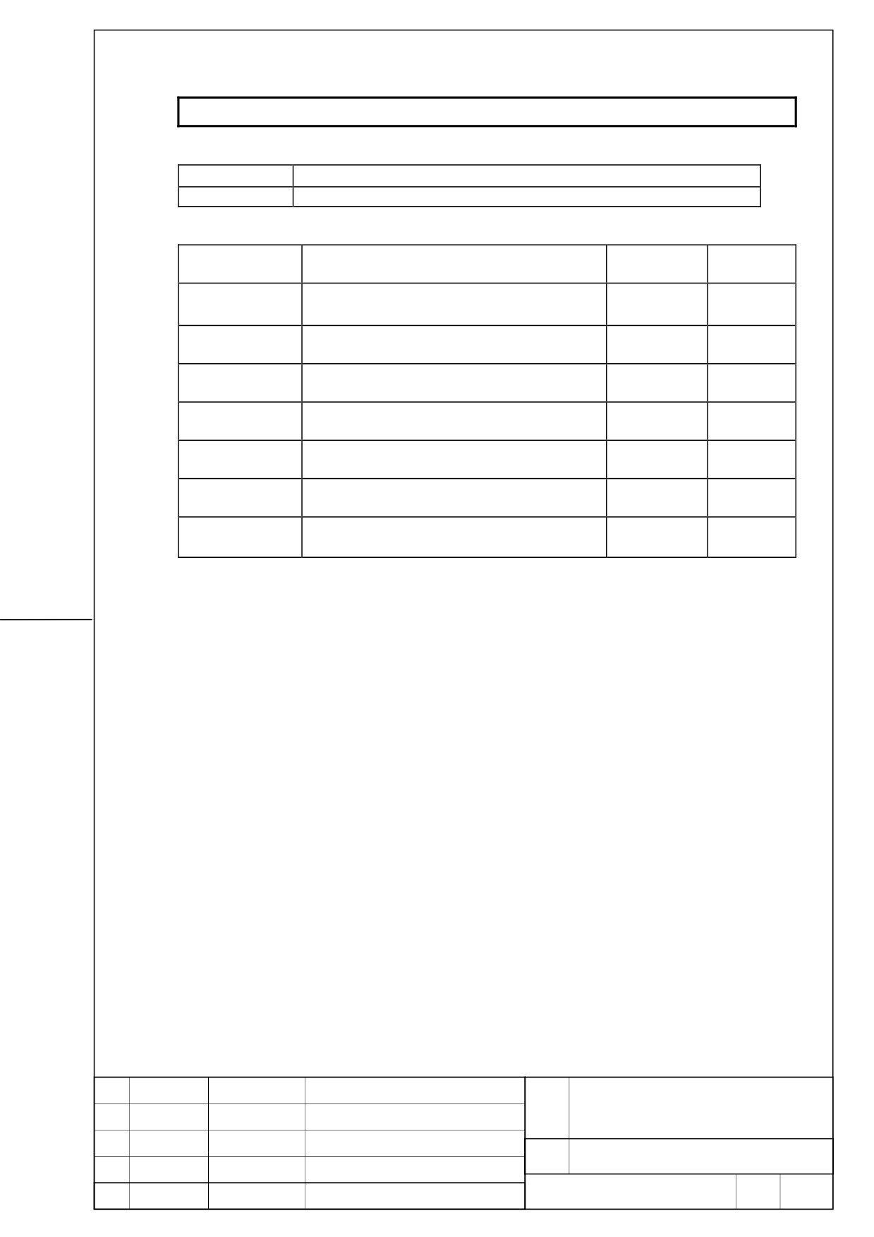
1. Type of applied documents
Name
FANUC SERVO AMPLIFIER βi series DESCRIPTIONS
Spec. No./Ver.
B-65322EN/02-02
2. Summary of Change
Group
Name / Outline
New, Add
Applicable
Correct, Del
Date
Basic Function
Optional
Function
Unit
Maintenance
Parts
Notice
Correction
Another
Addition of β(HV)i series SVM
New
2005. 1
FANUC SERVO AMPLIFIER
TITLE
βi series DESCRIPTIONS
DRAW.
No.
B-65322EN/02-02
01
05.01.18
K.Inaba
Add newly
EDIT
DATE
DESIGN
DESCRIPTION
FANUC LTD
Page
1 / 17
β(HV)i series SVM DESCRIPTIONS
This documents is described about the specification of β(HV)i series SVM.
Please refer to FANUC SERVO AMPLIFIER βi series DESCRIPTIONS (B-65322EN/02) about
contents without in this.
All specifications and designs are subject to change without notice.
FANUC SERVO AMPLIFIER
TITLE
βi series DESCRIPTIONS
DRAW.
No.
B-65322EN/02-02
EDIT
DATE
DESIGN
DESCRIPTION
FANUC LTD
Page
2 / 17
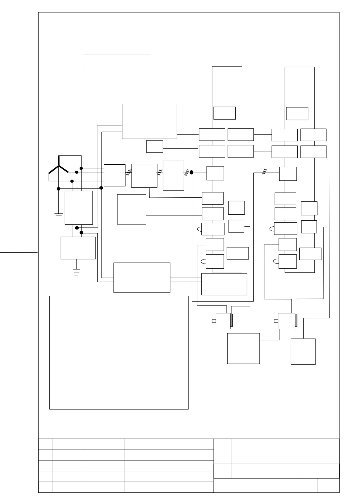
1.
Configuration
AC400V input type
βSVM1-40HVi
βSVM1-10HVi
or
βSVM1-20HVi
(CAUTION)
FUSE
FUSE
Stabilized power supply
DC24V
+24V etc
CXA19B
CXA19A
CXA19B
CXA19A
NC
Optical cable
COP10A
COP10A
COP10B
COP10B
3phase 400V to 480VAC
Optical cable
AC
Magnetic
Breaker
CZ4
CZ4
Line
contactor
filter
5A
Emergency
Magnetic contactor
CX29
CX29
Circuit
Stop switch
Control signal
JX5
JX5
breaker
CX30
CX30
Emergency stop signal
CXA20
JF1
CXA20
JF1
Lighting
CZ5
CZ5
surge absorber
CX5X
CX5X
CZ6
CZ6
Step-down transformer
AC230~AC277V
(CAUTION)
to AC200~AC240V
Fan unit
CAUTION
1.
The input voltage specification of a fan unit is AC200~AC 240V.
2.
Please confirm the input voltage specification of a stabilized power
supply.
3.
Please be sure to install a breaker, an electromagnetic contactor,
24V power
Battery
and AC line filter.
supply for
case
4.
Please be sure to use a stabilized
24VDC power supply for
motor brake
amplifier. Common use with 24V power supply for motor brakes
cannot be performed.
5.
The cabling of CX29 and CX30 of the second and subsequent
amplifiers may be omitted. Refer to “Total connection diagram” for
details.
FANUC SERVO AMPLIFIER
TITLE
βi series DESCRIPTIONS
DRAW.
No.
B-65322EN/02-02
EDIT
DATE
DESIGN
DESCRIPTION
FANUC LTD
Page
3 / 17
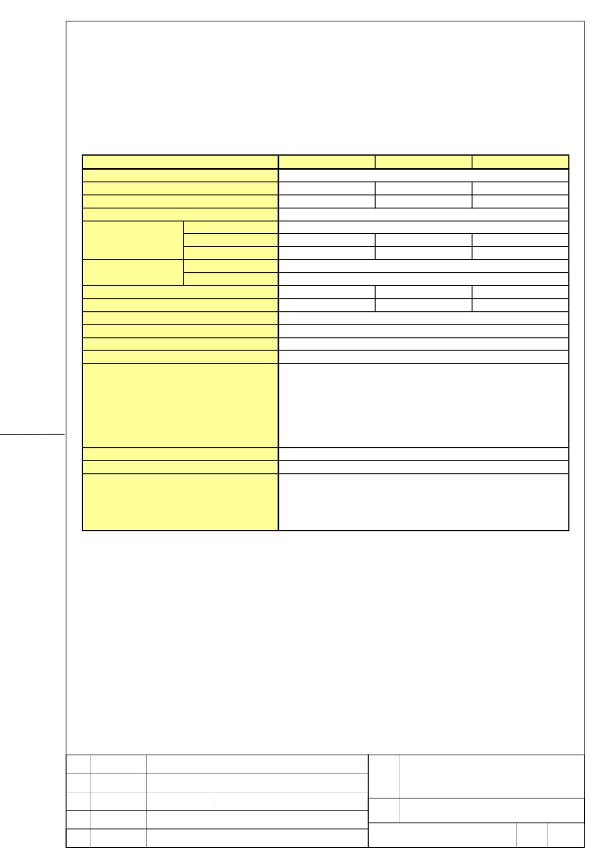
2. Specification
Item
SVM 1-10HVi
SVM 1-20HVi
SVM 1-40HVi
Interface
FSSB
Unit Designation
A06B-6131-H001
A06B-6131-H002
A06B-6131-H003
Power P.C.B.
A16B-3200-0515
A16B-3200-0516
A16B-3200-0517
Control P.C.B.
A20B-2101-0051
Main Power For
Input Voltage
AC 400-480 V (+10%,-15%)
50 / 60 Hz
Three Phase
Current at 50Hz
2.3 A rm s
3.6 A rm s
9.0A rm s
Supply
Rated Capacity
1.6 kV A
2.5 kV A
6.2kV A
Control
Input Voltage
DC 24 V (+10%,-10%)
Power supply
Input Current
0.9 A rm s
Rated Output Current
3.1A rm s
5.6A rm s
9.2A rm s
Current Limit Value
10Ap
20 Ap
40 Ap
Servo HRV control
HRV2,HRV3
Main Circuit Control Method
S ine W ave P W M C ontrolw ith T ransistor B ridges
D ynam ic brake circuit
Buit-in
Servo output frequency range
0-334Hz
- High C urrent
- IPM Abnorm al
- High Voltage of DC Link
- Low Voltage of DC Link
Warning and protectivefunctions
- O verheat of Discharge Resistor
- Low Voltage of C ontrolPower Supply
- FSSB C om m unication Error
- Locked Fan M otor
Ambient Temperature Range
0 to +55 degrees C elsius
Weight
3.9kg
Built-in regererative resistor
(64ohm ,50W no-w ind condition)
Option
(64ohm ,130W w ind velocity 2m /s condition)
Separated AC line filter
Separated battery
FANUC SERVO AMPLIFIER
TITLE
βi series DESCRIPTIONS
DRAW.
No.
B-65322EN/02-02
EDIT
DATE
DESIGN
DESCRIPTION
FANUC LTD
Page
4 / 17
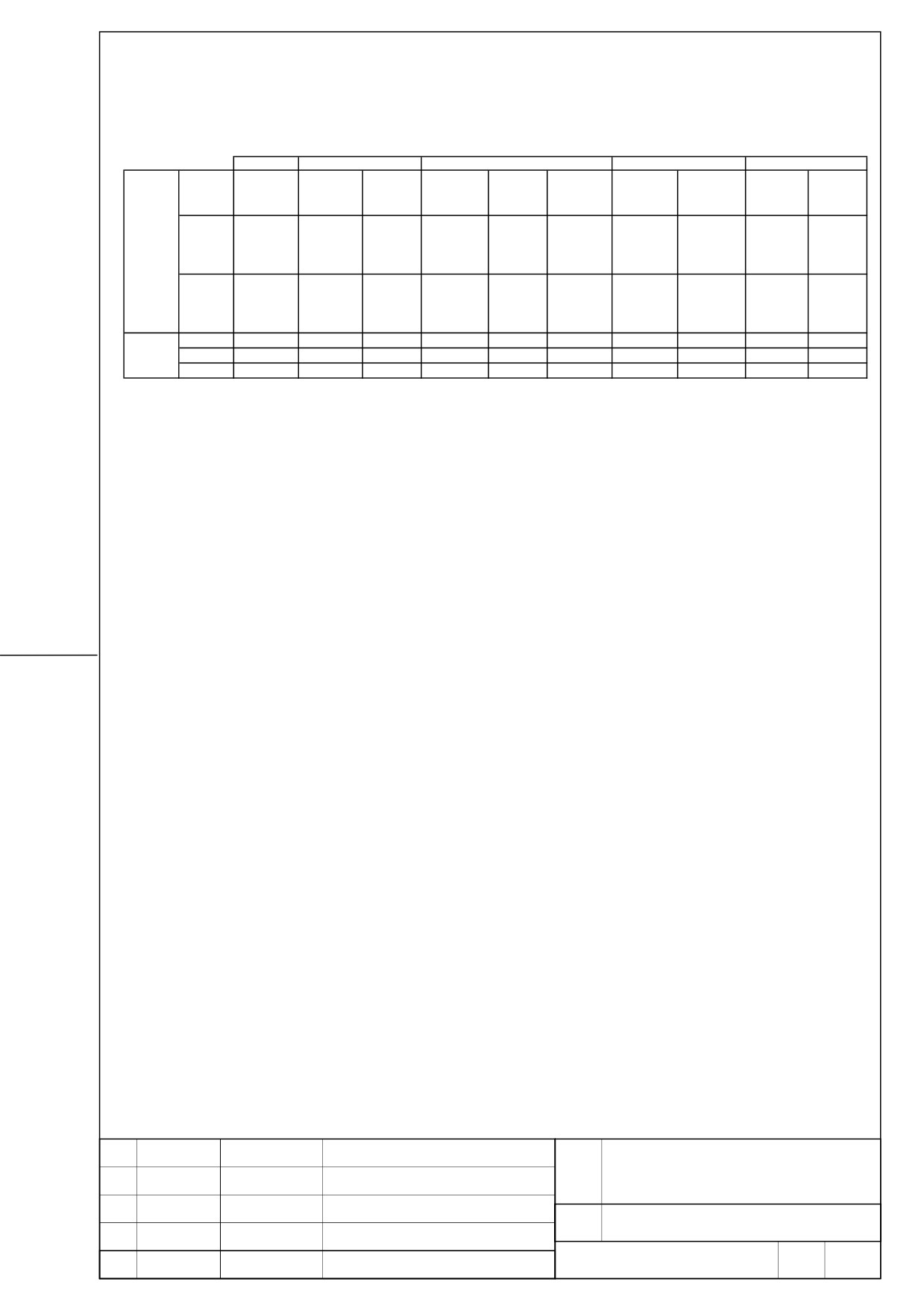
3. Applicable motors
2
4
8
22
α4
α8
α12
α22
/ 4000HVi
/ 3000HVi
/ 3000HVi
/ 3000HVi
αi
(20A)
(20A)
(40A)
(40A)
α2
α4
α8
α12
/ 5000HVi s
/ 5000HVi s
/ 4000HVi s
/ 4000HVi s
αis
(10A)
(10A)
(40A)
(40A)
MOTOR
β2
β4
β8
β12
β22
/ 4000HVi s
/ 4000HVis
/ 3000HVi s
/ 3000HVi s
/ 2000HVi s
βis
(10A)
(10A)
(10A)
(20A)
(20A)
SVM1-
10HVi
○
○
○
20HVi
○
○
○
○
40HVi
○
○
○
FANUC SERVO AMPLIFIER
TITLE
βi series DESCRIPTIONS
DRAW.
No.
B-65322EN/02-02
EDIT
DATE
DESIGN
DESCRIPTION
FANUC LTD
Page
5 / 17
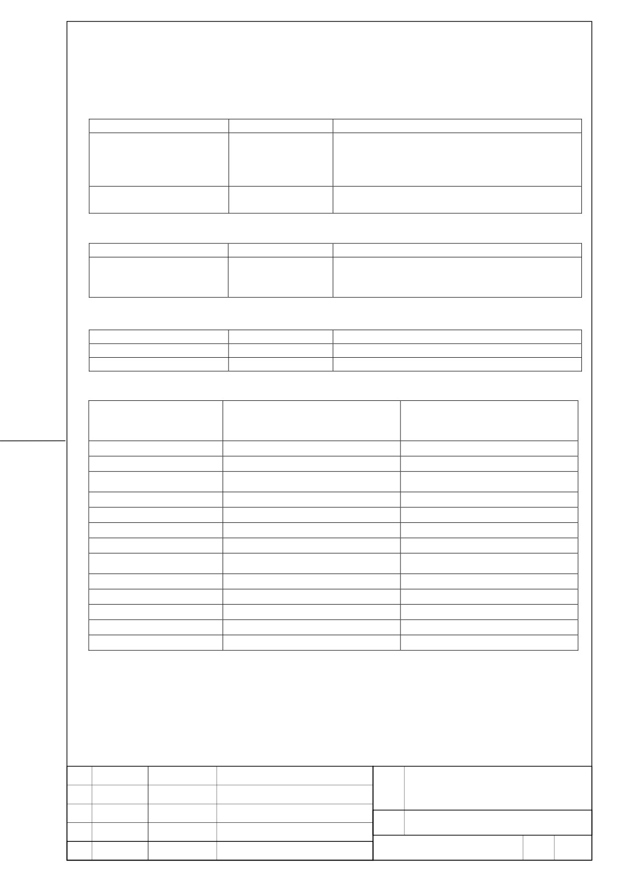
4. Selection of breaker, electromagnetic contactor, and AC line filter
4.1. Breaker
Name
Specification
Note
The breaker for
A06B-6077-K101
Fuji Electric EA53B/30+ cover BZ-TB20B-3
main power supplies
(30A)
The breaker for
A06B-6077-K106
Fuji Electric EA33/5+ cover BZ-TB10B-503
control sources (5A)
4.2. Electromagnetic contactor
Name
Specification
Note
Electromagnetic
A06B-6077-K121
Fuji Electric SC-5-1+ cover SZ-JC4
contactor
(32A)
4.3. AC line filter
Name
Specification
Note
AC line filter
A81L-0001-0168
AC line filter
A81L-0001-0169
Please refer to the following table and select it. For details, please refer to B-65322/02JA.
Servo motor
Continuous rating current
Power supply capacity
[Arms]
[kVA]
(Reference value)
(Reference value)
β2/4000HVis
1.2
0.8
β 4/4000HVis
1.7
1.2
β 8/3000HVis
1.9
2.7
β12/3000HVis
4.0
2.8
β 22/2000HVis
5.6
3.9
α2/5000HVis
1.7
1.2
α4/5000HVis
2.3
1.6
α4/4000HVi
2.2
3.2
α8/3000HVi
3.6
2.5
α8/4000HVis
5.2
3.6
α12/4000HVis
5.6
3.9
α12/3000HVi
6.7
4.7
α22/3000HVi
9.0
6.2
FANUC SERVO AMPLIFIER
TITLE
βi series DESCRIPTIONS
DRAW.
No.
B-65322EN/02-02
EDIT
DATE
DESIGN
DESCRIPTION
FANUC LTD
Page
6 / 17
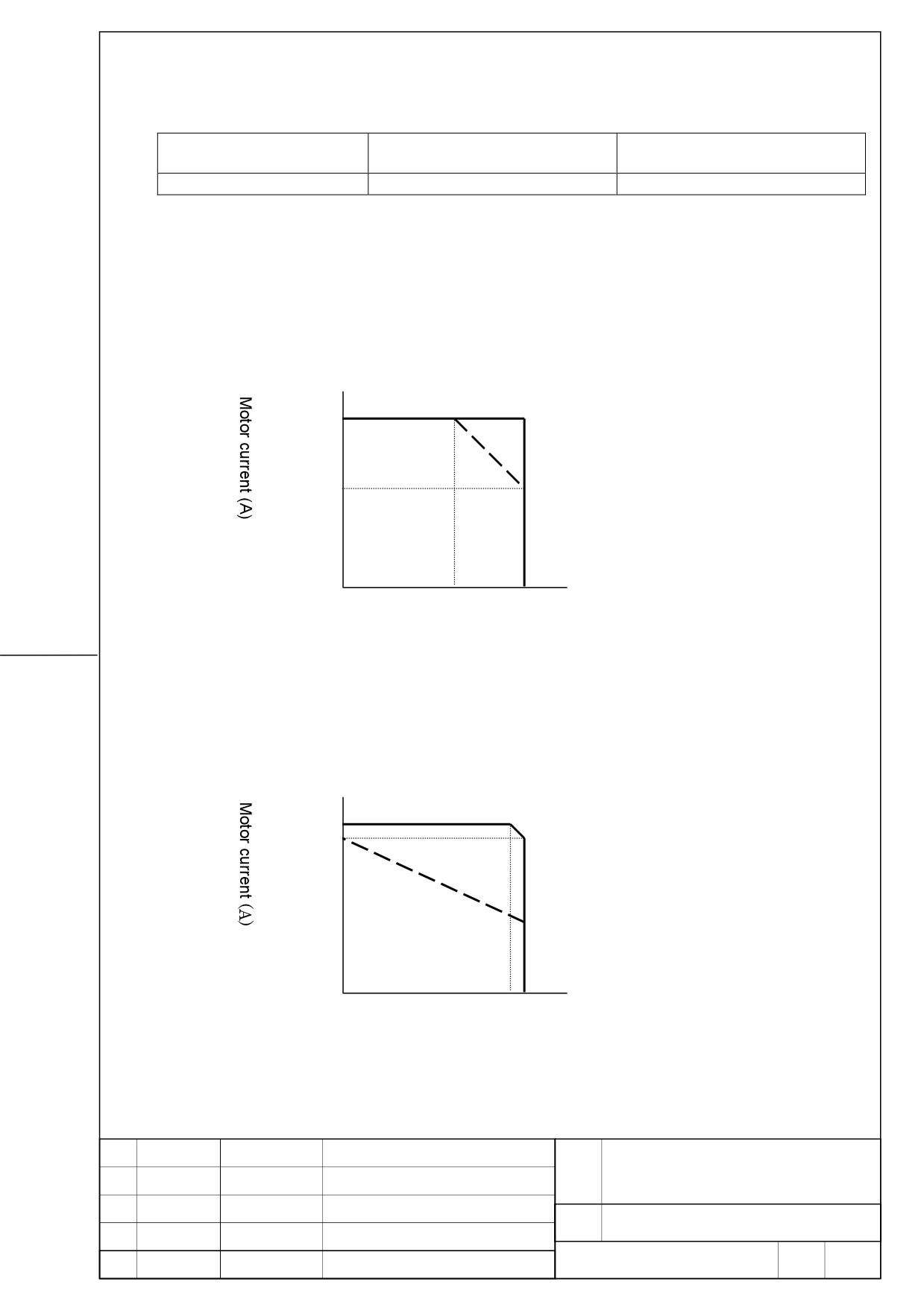
5. Cooling fan motor
The fan motor for amplifier cooling is needed for the following model.
Ordering number
Amplifier
Applied motor
A06B-6134-K002
SVM1-40HVi
All motors
6. Derating
Consider derating as shown below, according to ambient temperature.
The solid line is a derating line for use when HRV2, while the dotted line is a derating line for
use when HRV3 is applied.
SVM1-20HVi
Motor current derating
5.6
3.4
30
55
Ambient temperature (Degree)
SVM1-40HVi
Motor current derating
9.2
8.3
0
0
50 55
Ambient temperature (Degree)
FANUC SERVO AMPLIFIER
TITLE
βi series DESCRIPTIONS
DRAW.
No.
B-65322EN/02-02
EDIT
DATE
DESIGN
DESCRIPTION
FANUC LTD
Page
7 / 17
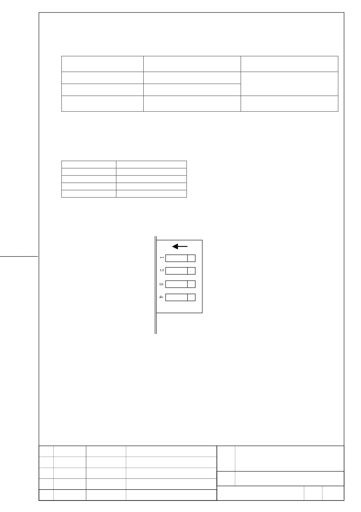
7. Capacity of regeneration discharge resistor
The regeneration discharge resistor of the following capacity is built in the servo amplifier
module.
Amplifier
Specification
Capacity of regeneration
discharge resistance
SVM1-10HVi
50W
A06B-6131-H001
SVM1-20HVi
No -wind condition
A06B-6131-H002
SVM1-40HVi
130W
A06B-6131-H003
Wind velocity 2m/s condition
8. Setup switch (For DC alarm level)
Since the switch of four channels is in the front of a servo amplifier module for regeneration
resistance protection, please make it the following setup.
Switch
Setup
Switch1
OFF
Switch2
OFF
Switch3
ON
Switch4
ON
ON
FANUC SERVO AMPLIFIER
TITLE
βi series DESCRIPTIONS
DRAW.
No.
B-65322EN/02-02
EDIT
DATE
DESIGN
DESCRIPTION
FANUC LTD
Page
8 / 17
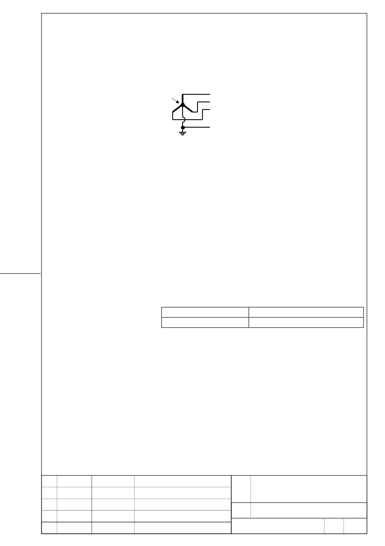
9. Power supply specification
9.1. Three-phase input power supply for motor power
-
Nominal rating voltage: 400V to 480VAC
Star connection, neutral grounding
PE is provided on the power line
R
N
S
T
G
- Allowable voltage fluctuation: -15% - +10%
- Frequency: 50/60Hz
- Allowable frequency fluctuation: ±2Hz
- Power supply impedance : Voltage fluctuation by load (at
maximum output) not be exceed 7%.
- Power supply Unbalance: ±5% or less of rated voltage
9.2. Single-phase input for control power
Please be sure to use a regulated power supply for 24V power supply for amplifier.
Common use with 24V power supply for motor brakes cannot be performed.
- Nominal rating voltage: 24VDC
- Allowable voltage fluctuation: ±10% (Including momentary
variations)
- Power supply capacity
Power supply capacity per amplifier
FSSB interface
0.9A
FANUC SERVO AMPLIFIER
TITLE
βi series DESCRIPTIONS
DRAW.
No.
B-65322EN/02-02
EDIT
DATE
DESIGN
DESCRIPTION
FANUC LTD
Page
9 / 17
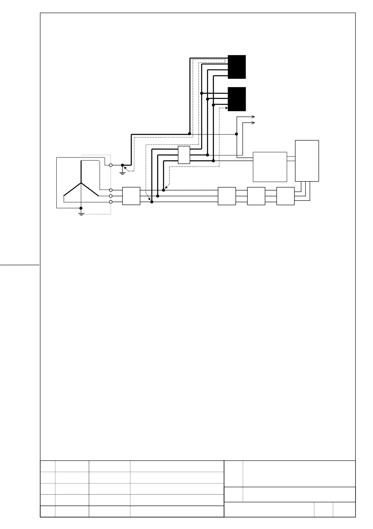
10. Installing of lighting surge absorber
Lighting surge absorber between each
power line and ground
(R.A.V-801BXZ-4)
Lighting surge absorber between
power lines
(R.A.V-152BYZ-2A)
Power supply
(a)
To other units
(Grounded to a neutral point on
Control power
tthe Y wire)
(b)
input
AC400V/480V
Stabilized
power supply
Circuit breaker 2 (5A)
βiSVM
(DC24V)
Ground plate
Main circuit
power input
Ground-fault circuit
Circuit breaker 1
Magnetic
AC line filter
interrupter for power
contactor
magnetic cabinet
CAUTIONS
(1) To increase the efficiency of lightning surge absorption, the wires indicated by bold
lines should be as short as possible.
Wire cross-sectional area : 2 mm2 or more
Wire length :
The total length of the cables used for line-to-line lightning surge protector (a) and
that used for line-to-ground lightning surge protector (b) must not exceed 2 m.
(2) When performing a dielectric strength test by applying an overvoltage to the power
line, line-to-ground lightning surge protector must be removed to enable the applied
voltage to be maintained.
(3) The circuit breaker 2 (5A) works for line protection when the lightning surge absorber
is short-circuited because of a surge higher than its rating being applied.
(4) Because current does not flow through lightning surge protector in a normal state, the
circuit breaker 2 (5A) can be used together with the surge absorbers as well as with
other equipment.
FANUC SERVO AMPLIFIER
TITLE
βi series DESCRIPTIONS
DRAW.
No.
B-65322EN/02-02
EDIT
DATE
DESIGN
DESCRIPTION
FANUC LTD
Page
10 / 17
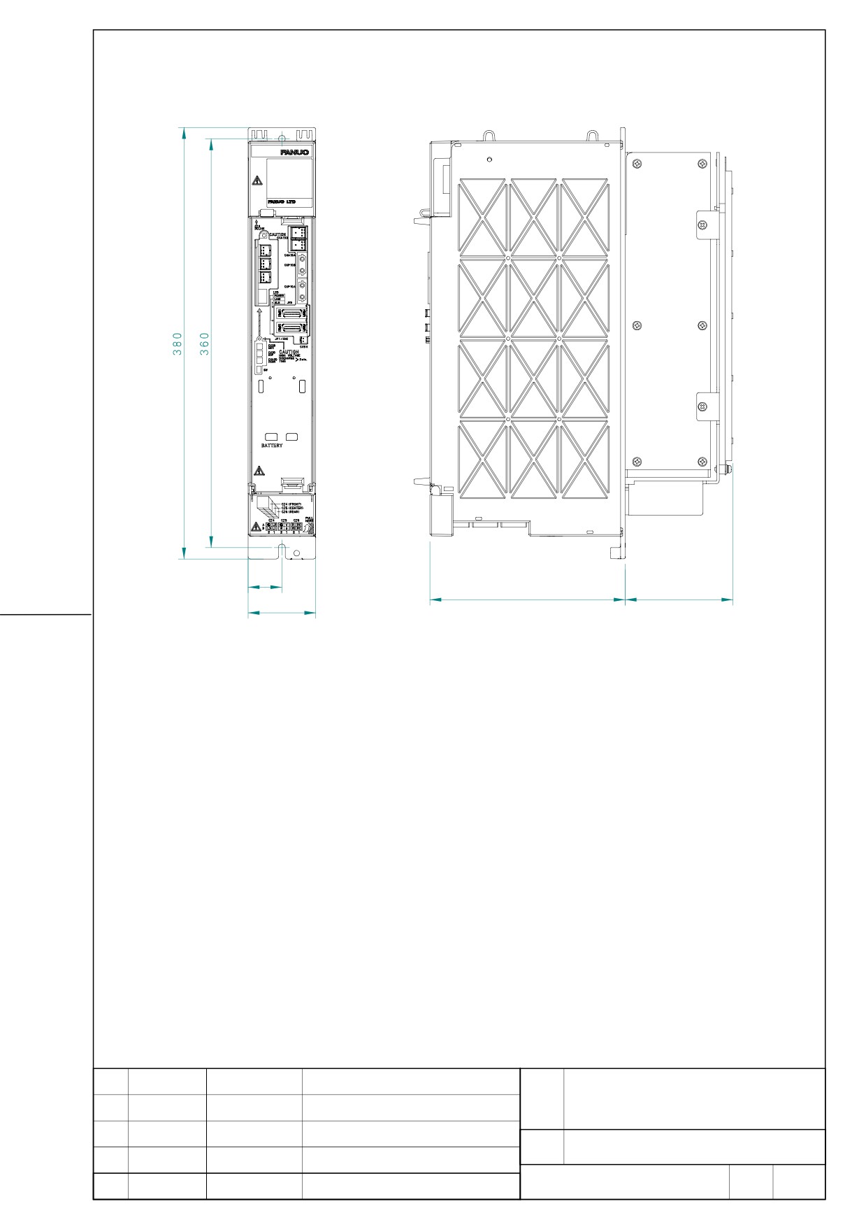
11. External dimention/ Panel cut-out drawing/ maintenance area
11.1. SVM1-10HVi, SVM1-20HVi, SVM1-40HVi
Yamanashi 401-0597 JAPAN
30
172
100 max.
60
External dimensions/ panel cut-out/ maintenance area is the same as SVM1-40i and
SVM1-80i. Please refer to B-65322/02EN for details.
FANUC SERVO AMPLIFIER
TITLE
βi series DESCRIPTIONS
DRAW.
No.
B-65322EN/02-02
EDIT
DATE
DESIGN
DESCRIPTION
FANUC LTD
Page
11 / 17
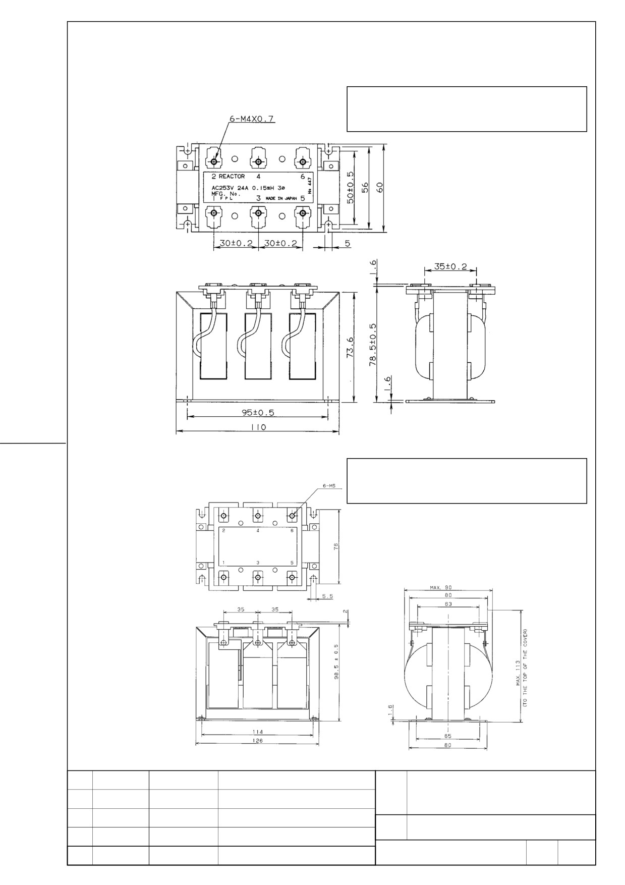
11.2. AC line filter
11.2.1 A81L-0001-0168
NOTE
The outer diagram and dimension may be
changed without announcement.
11.2.2 A81L-0001-0169
NOTE
The outer diagram and dimension may be
changed without announcement.
FANUC SERVO AMPLIFIER
TITLE
βi series DESCRIPTIONS
DRAW.
No.
B-65322EN/02-02
EDIT
DATE
DESIGN
DESCRIPTION
FANUC LTD
Page
12 / 17
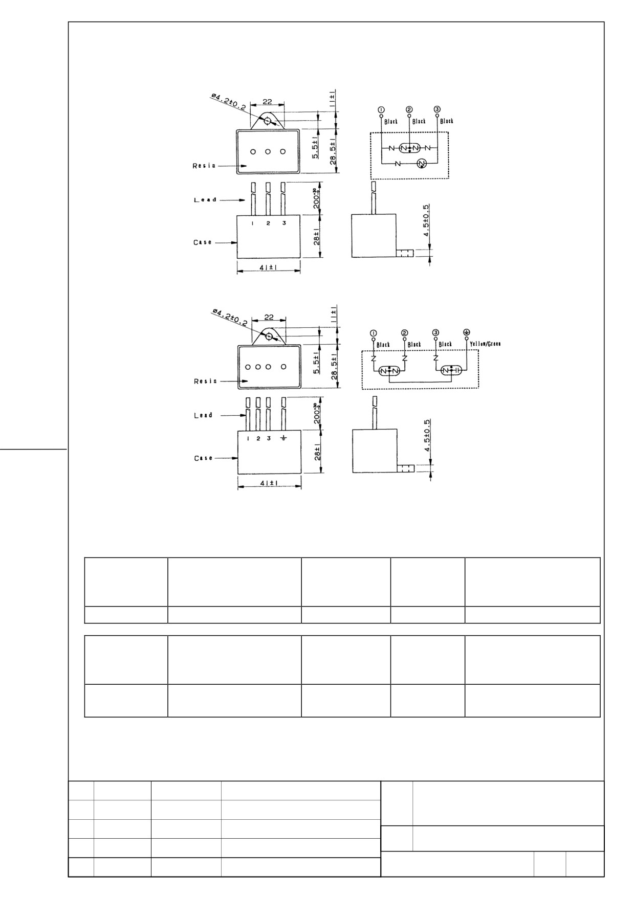
11.3. Lighting surge absorber A06B-6077-K143
Connection diagram
(1) For line-to-line installation: RAV-152BYZ-2A
Connection diagram
(2) For line-to-ground installation: RAV-801BXZ-4
Surge
Specification
Rated voltage
Clamp voltage
withstand
Surge withstand voltage
current
R⋅A⋅V-152BYZ-2A
460VAC
1470V ±10%(V1.0)
2500A(8/20µS)
20kV(1.2/50µS)
Surge
AC discharge start
Maximum surge discharge
Specification
Rated voltage
withstand
voltage
start voltage
current
line-to-line: 500VAC,
R⋅A⋅V-801BXZ-4
800VAC ±20%(Ua)
2500A(8/20µS)
2.32kV(1.2/50µS)
line-to-ground: 290VAC
FANUC SERVO AMPLIFIER
TITLE
βi series DESCRIPTIONS
DRAW.
No.
B-65322EN/02-02
EDIT
DATE
DESIGN
DESCRIPTION
FANUC LTD
Page
13 / 17
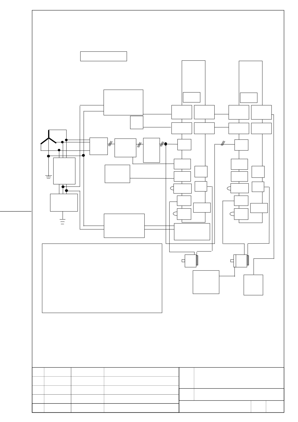
12. Total connection diagram
AC400V input type
βSVM1-40HVi
βSVM1-10HVi
or
βSVM1-20HVi
(CAUTION)
FUSE
FUSE
Stabilized power supply
DC24V
K11
K6
CXA19B
CXA19A
CXA19B
CXA19A
NC
Optical
COP10A
COP10A
COP10B
COP10B
3phase 400V to 480VAC
Optical cable
Breaker
Magnetic
AC
CZ4
CZ4
K2
K2
contactor
Line
filter
5A
CX29
CX29
K7
Circuit
Emergency
JX5
JX5
breaker
stop switch
CX30
CX30
K8
CXA20
JF1
K5
CXA20
JF1
K5
Lighting
CZ5
CZ5
surge absorber
CX5X
CX5X
CZ6
CZ6
K10
K10
Step-down transformer
K4
K4
AC230~AC277V
(CAUTION)
to AC200~AC240V
Fan unit
K3
K1
K3
K1
CAUTION
K9
1.
The input voltage specification of a fan unit is AC200~AC 240V.
2.
Please confirm the input voltage specification of a stabilized power supply.
3.
Please be sure to install a breaker, an electromagnetic contactor, and AC
24V power
line filter.
Battery
supply for
4.
Please be sure to use a stabilized 24VDC power supply for amplifier.
case
motor brake
Common use with 24V power supply for motor brakes cannot be performed.
5.
The cabling of CX29 and CX30 of the second and subsequent amplifiers
may be omitted. Refer to “Total connection diagram” for details.
FANUC SERVO AMPLIFIER
TITLE
βi series DESCRIPTIONS
DRAW.
No.
B-65322EN/02-02
EDIT
DATE
DESIGN
DESCRIPTION
FANUC LTD
Page
14 / 17
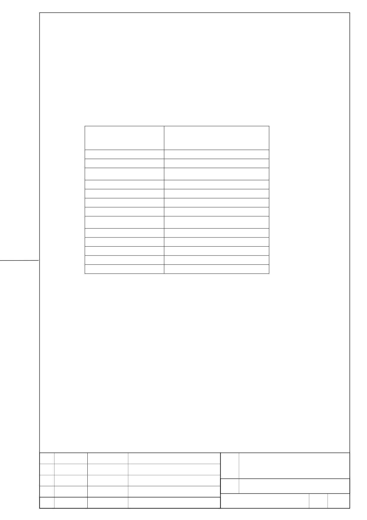
12.1. Connection details
Refer to Section [ I. .SVM ] of B-65322EN/02 for details.
12.1.1. Details of cable K2 (Refer to B-65322/02EN)
Please select specification of cables in consideration of
following
table.
Refer
to
Section [ I .SVM ] of B-65322EN/02 for details.
Servo motor
Continuous rating current
[Arms]
(Reference value)
β2/4000HVis
1.2
β4/4000HVis
1.7
β8/3000HVis
2.7
β12/3000HVis
4.0
β22/2000HVis
5.6
α2/5000HVis
1.7
α4/5000HVis
2.3
α4/4000HVi
3.2
α8/3000HVi
3.6
α8/4000HVis
5.2
α12/4000HVis
5.6
α 12/3000HVi
6.7
α22/3000HVi
9.0
FANUC SERVO AMPLIFIER
TITLE
βi series DESCRIPTIONS
DRAW.
No.
B-65322EN/02-02
EDIT
DATE
DESIGN
DESCRIPTION
FANUC LTD
Page
15 / 17
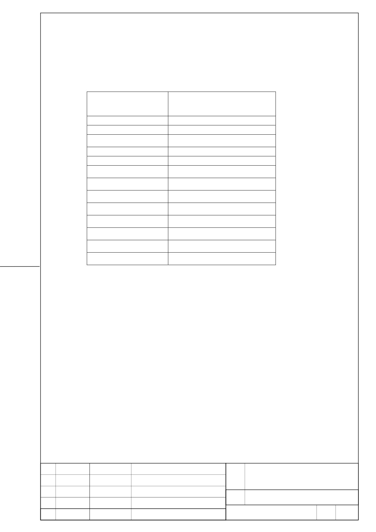
12.1.2. Details of cable K3 (Refer to B-65322/02EN)
Please select specification of cables in consideration of
following
table.
Refer
to
Section [ I. .SVM ] of B-65322EN/02 for details.
Servo motor
Continuous rating current
[Arms]
(Reference value)
β2/4000HVis
1.7
β4/4000HVis
2.4
β8/3000HVis
3.1
β12/3000HVis
5.1
β22/2000HVis
5.7
1.7
α2/5000HVis
3.1
α4/5000HVis
α4/4000HVi
4.1
4.2
α8/3000HVi
5.6
α8/4000HVis
6.7
α12/4000HVis
9.1
α12/3000HVi
9.2
α 22/3000HVi
FANUC SERVO AMPLIFIER
TITLE
βi series DESCRIPTIONS
DRAW.
No.
B-65322EN/02-02
EDIT
DATE
DESIGN
DESCRIPTION
FANUC LTD
Page
16 / 17