FANUC Series 0i-MODEL D, Series 0i Mate-MODEL D. For Machining Center System USER’S MANUAL - page 5
5. FUNCTIONS TO SIMPLIFY
PROGRAMMING
PROGRAMMING
B-64304EN-2/01
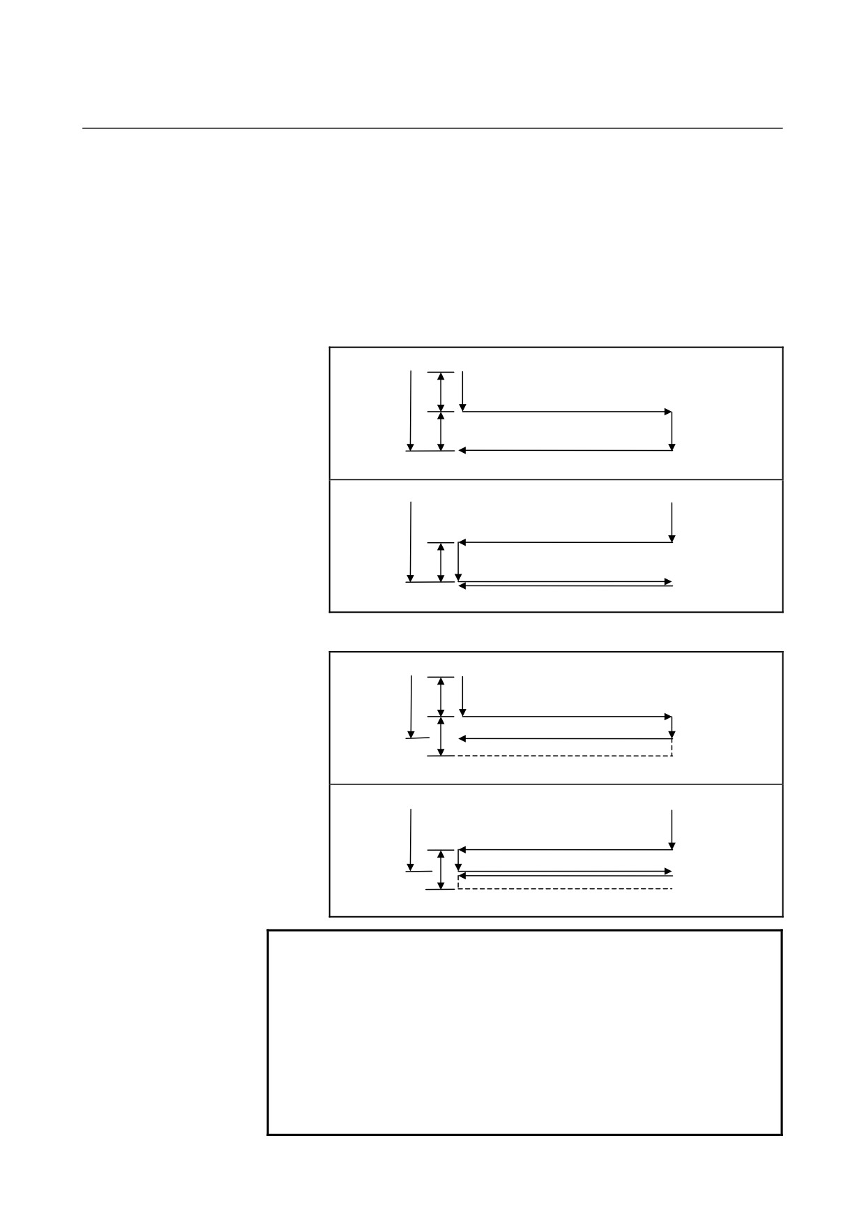
- Operation to be performed if the total depth of cut is reached
If, during cutting with I or J, the total depth of cut is reached, the cycle
is ended after the subsequent operations in the sequence (up to <6>)
are executed.
If this occurs, the depth of cut is equal to or less than the total depth of
cut.
•
If the total depth of cut is reached due to a cutting operation with
I or J
<1>
I
K
<3>
<2>
<4>
J
<6>
<5>
K
I
<1>
<2>
<3>
<5>
<6>
•
If the total depth of cut is reached during a cutting operation with
I or J
<1>
I
K
<3>
<2>
<4>
J
<5>
<6>
K
<1>
<3>
I
<2>
<5>
<6>
NOTE
1 If I, J, and K have different signs, alarm PS0455 is issued.
2 If G75 is specified, but a grinding axis is not specified,
alarm PS0455 is issued.
3 If any two of the cutting axis number, the grinding axis
number, and the dressing axis number are the same, alarm
PS0456 is issued.
4 While this cycle is effective, even if G90 (absolute
command) is executed, the α, I, J, and K commands are
incremental ones.
- 106 -
5.FUNCTIONS TO SIMPLIFY
B-64304EN-2/01
PROGRAMMING
PROGRAMMING
5.6.2
Direct Constant-Dimension Plunge Grinding Cycle (G77)
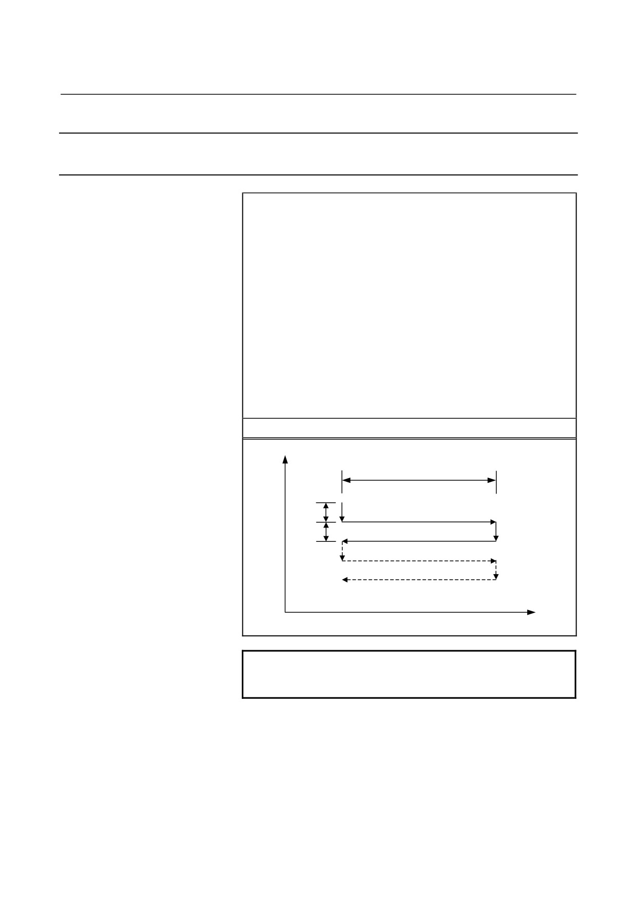
A direct constant-dimension plunge grinding cycle can be performed.
Format
G77 I_ J_ K_ α_ R_ F_ P_ L_ ;
I_ : First depth of cut (The cutting direction depends on the
sign.)
J_ : Second depth of cut (The cutting direction depends on
the sign.)
K_ : Total depth of cut (The cutting direction depends on the
sign.)
α_ : Grinding range (The grinding direction depends on the
sign.)
R_: Feedrate for I and J
F_ : Feedrate for α
P_ : Dwell time
L_ : Grinding-wheel wear compensation number (during
continuous dressing only)
G77
Y
α
I
<1> (R)
<3> (F)
<2> P
<4> (R)
J
<6> (F)
<5> P
α
NOTE
α is an arbitrary axis address on the grinding axis
as determined with parameter No. 5177.
- 107 -
5. FUNCTIONS TO SIMPLIFY
PROGRAMMING
PROGRAMMING
B-64304EN-2/01
Explanation
A direct constant-dimension plunge grinding cycle consists of a
sequence of six operations.
Operations <1> to <6> are repeated until the depth of cut reaches the
total depth of cut specified with address K. For a single block,
operations <1> to <6> are executed with a single cycle start.
- Operation sequence in a cycle
<1> Cutting with a grinding wheel
Makes a cut in the Y-axis direction with cutting feed by the amount
specified as the first depth of cut I. The feedrate is the one specified
with R.
<2> Dwell
Performs a dwell for the time specified with P.
<3> Grinding
Causes the machine to move with cutting feed by the amount specified
with α. The grinding axis is specified with parameter No. 5177. The
feedrate is the one specified with F. If L is specified when the
continuous dressing function is enabled, dressing is performed with
the cutting axis and the dressing axis. The dressing axis is specified
with parameter No. 5181.
<4> Cutting with a grinding wheel
Makes a cut in the Y-axis direction with cutting feed by the amount
specified as the second depth of cut J. The feedrate is the one specified
with R.
<5> Dwell
Performs a dwell for the time specified with P.
<6> Grinding (return direction)
Feeds the machine at the feedrate specified with F in the opposite
direction by the amount specified with α. If L is specified when the
continuous dressing function is enabled, dressing is performed with
the cutting axis and the dressing axis.
- Continuous dressing
If the continuous dressing function is enabled, the grinding-wheel cut
and the dresser cut are continuously compensated for according to the
dressing amount specified with L during the execution of grinding.
For details, see Explanation of G75.
- 108 -
5.FUNCTIONS TO SIMPLIFY
B-64304EN-2/01
PROGRAMMING
PROGRAMMING
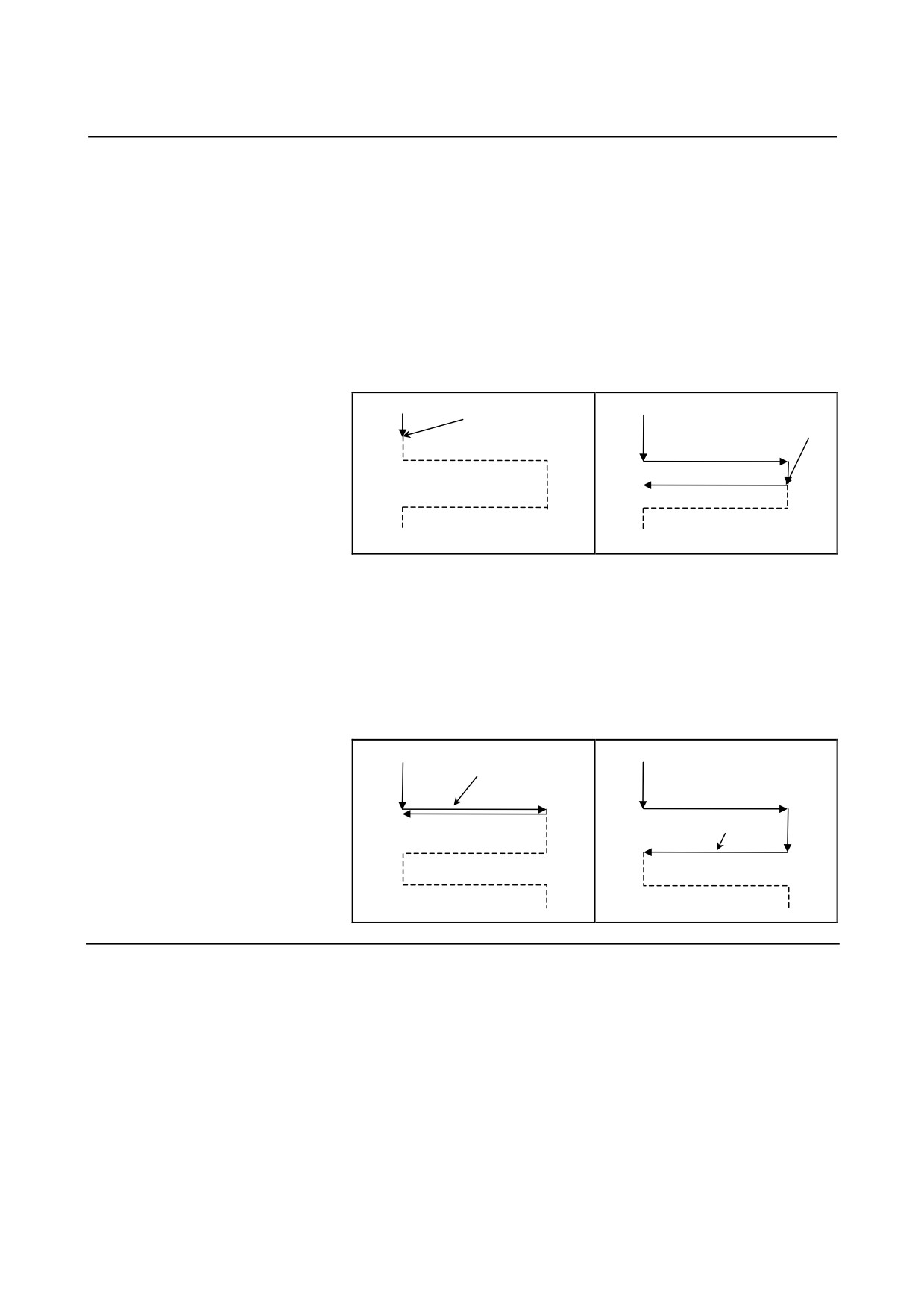
- Operation to be performed when a skip signal is input
With G77, by inputting a skip signal in a cycle, it is possible to end
the cycle after interrupting the current operation sequence (or after
ending the current operation sequence).
The following shows the operation to be performed when a skip signal
is input in each operation sequence.
•
If operation <1> or <4> in the sequence (movement with I or J)
is in progress, the machine immediately stops cutting and returns
to the α coordinate, assumed at the start of the cycle.
Skip signal
Skip signal
(End)
(End)
•
If operation <2> or <5> in the sequence (dwell) is in progress,
the machine immediately cancels the dwell and returns to the α
coordinates, assumed at the start of the cycle.
•
If operation <3> or <6> in the sequence (grinding movement) is
in progress, the machine returns to the α coordinate, assumed at
the start of the cycle after the end of the α movement.
Skip signal
(End)
Skip signal
(End)
Limitations
- Cutting axis
The cutting axis is the second controlled axis. By setting bit 0 (FXY)
of parameter No. 5101 to 1, the axis can be switched with a plane
selection command (G17, G18, or G19).
- Grinding axis
To specify a grinding axis, set its axis number, which must be other
than that of the cutting axis, in parameter No. 5177.
- Dressing axis
To specify a dressing axis, set its axis number, which must be other
than those of the cutting axis and the grinding axis, in parameter No.
5181.
- 109 -
5. FUNCTIONS TO SIMPLIFY
PROGRAMMING
PROGRAMMING
B-64304EN-2/01
- α,I,J,K
α, I, J, and K commands are all incremental ones.
Spark-out (execution of movement in the grinding direction only)
occurs in the following cases:
•
I or J is not specified or I = J = 0
•
K is not specified or K = 0
If I or J is not specified or if I = J = 0 is true, and K is not equal to 0, a
grinding operation is performed infinitely.
- Clearing
The data items I, J, K, α, R, F, and P in a canned cycle are modal
information common to G75, G77, G78, and G79, so that once
specified, they remain effective until specified anew. The data is
cleared when a G code of group 00 other than G04 or a G code of
group 01 other than G75, G77, G78, and G79 is specified. L is
effective only in the block in which it is specified.
- Operation to be performed if the total depth of cut is reached
The operation to be performed if the total depth of cut reaches during
cutting with I or J is the same as that for G75. See Limitation on
G75.
NOTE
1 If I, J, and K have different signs, alarm PS0455 is
issued.
2 If G77 is specified, but a grinding axis is not
specified, alarm PS0455 is issued.
3 If any two of the cutting axis number, the grinding
axis number, and the dressing axis number are the
same, alarm PS0456 is issued.
4 While this cycle is effective, even if G90 (absolute
command) is executed, the α, I, J, and K
commands are incremental ones.
- 110 -
5.FUNCTIONS TO SIMPLIFY
B-64304EN-2/01
PROGRAMMING
PROGRAMMING
5.6.3
Continuous-feed Surface Grinding Cycle (G78)
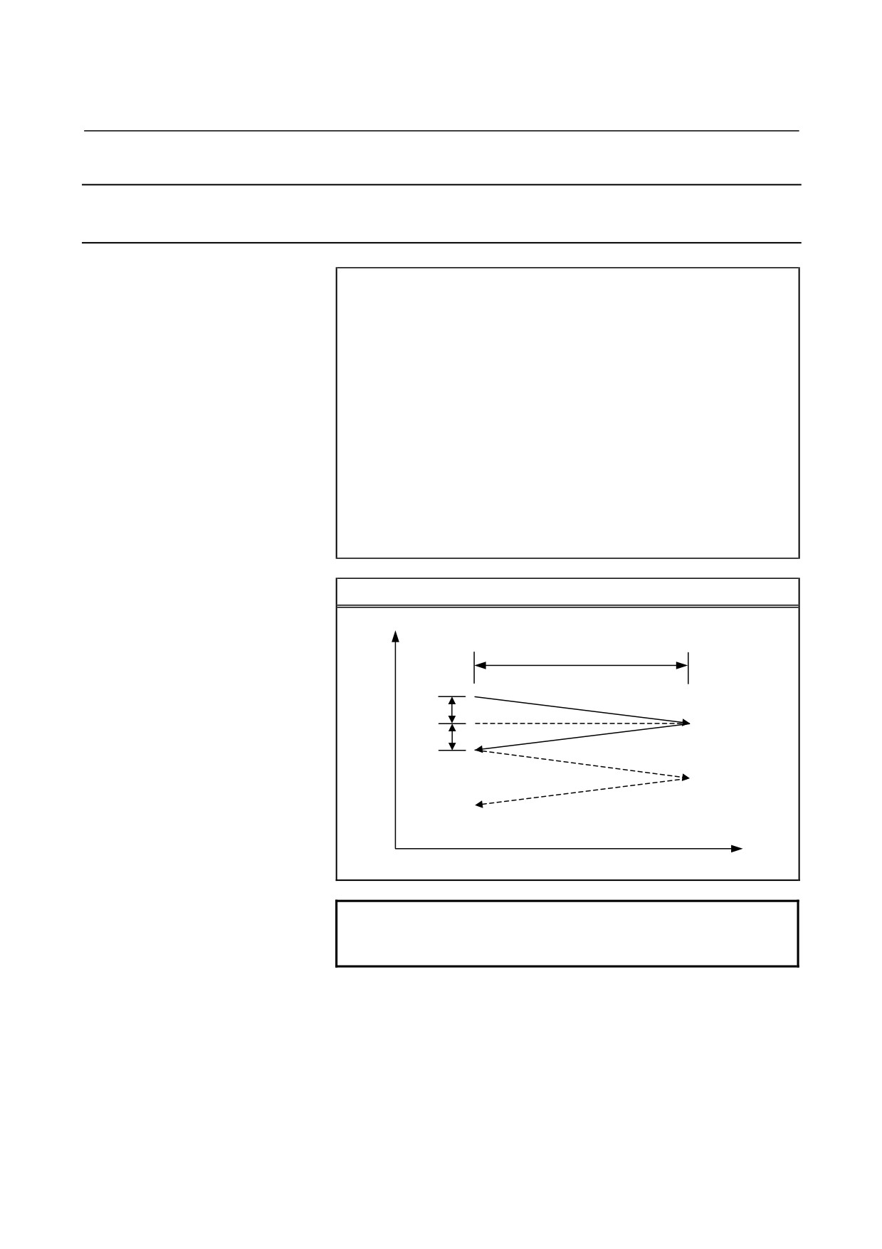
A continuous-feed surface grinding cycle can be performed.
Format
G78 I_ (J_) K_ α_ F_P_ L_ ;
I_ : First depth of cut (The cutting direction depends on the
sign.)
J_ : Second depth of cut (The cutting direction depends on
the sign.)
K_ : Total depth of cut (The cutting direction depends on the
sign.)
α_ : Grinding range (The grinding direction depends on the
sign.)
F_ : Feedrate for α
P_ : Dwell time
L_ : Grinding-wheel wear compensation number (during
continuous dressing only)
G78
Z
α
<1> P
<2> (F)
I
I(J)
<3> P
<4> (F)
α
NOTE
α is an arbitrary axis address on the grinding axis
as determined with parameter No. 5178.
- 111 -
5. FUNCTIONS TO SIMPLIFY
PROGRAMMING
PROGRAMMING
B-64304EN-2/01
Explanation
A continuous-feed surface grinding cycle consists of a sequence of
four operations.
Operations <1> to <4> are repeated until the depth of cut reaches the
total depth of cut specified with address K. For a single block,
operations <1> to <4> are executed with a single cycle start.
- Operation sequence in a cycle
<1> Dwell
Performs a dwell for the time specified with P.
<2> Cutting with a grinding wheel+Grinding
Performs cutting feed along the cutting axis (Z-axis) and the grinding
axis at the same time. The travel distance (depth of cut) along the
cutting axis is equal to the amount specified as the first depth of cut I,
and the travel distance along the grinding axis is equal to the amount
specified with α. The grinding axis is specified with parameter No.
5178. The feedrate is the one specified with F. If L is specified when
the continuous dressing function is enabled, dressing is performed
with the cutting axis and the dressing axis. The dressing axis is
specified with parameter No. 5182.
<3> Dwell
Performs a dwell for the time specified with P.
<4> Cutting with a grinding wheel+Grinding (return direction)
Performs cutting feed along the cutting axis (Z-axis) and the grinding
axis at the same time. The travel distance (depth of cut) along the
cutting axis is equal to the amount specified as the first depth of cut I,
and the travel distance along the grinding axis is equal to the amount
specified with α, with the direction being the opposite one. The
feedrate is the one specified with F. If L is specified when the
continuous dressing function is enabled, dressing is performed with
the cutting axis and the dressing axis.
- Continuous dressing
If the continuous dressing function is enabled, the grinding-wheel cut
and the dresser cut are continuously compensated for according to the
dressing amount specified with L during the execution of grinding.
For details, see Explanation of G75.
- 112 -
5.FUNCTIONS TO SIMPLIFY
B-64304EN-2/01
PROGRAMMING
PROGRAMMING
Limitations
- Cutting axis
The cutting axis is the third controlled axis. By setting bit 0 (FXY) of
parameter No. 5101, the axis can be switched with a plane selection
command (G17, G18, or G19).
- Grinding axis
To specify a grinding axis, set its axis number, which must be other
than that of the cutting axis, in parameter No. 5178.
- Dressing axis
To specify a dressing axis, set its axis number, which must be other
than those of the cutting axis and the grinding axis, in parameter No.
5182.
- J
If J is not specified, J is regarded as being equal to I.
The J command is effective only in the block in which it is specified.
- α,I,J,K
α, I, J, and K commands are all incremental ones.
Spark-out (execution of movement in the grinding direction only)
occurs in the following cases:
•
I or J is not specified or I = J = 0
•
K is not specified or K = 0
If I or J is not specified or if I = J = 0 is true, and K is not equal to 0, a
grinding operation is performed infinitely.
- Clearing
The data items I, K, α, R, F, and P in a canned cycle are modal
information common to G75, G77, G78, and G79, so that once
specified, they remain effective until specified anew. The data is
cleared when a G code of group 00 other than G04 or a G code of
group 01 other than G75, G77, G78, and G79 is specified. J, L is
effective only in the block in which it is specified.
- 113 -
5. FUNCTIONS TO SIMPLIFY
PROGRAMMING
PROGRAMMING
B-64304EN-2/01
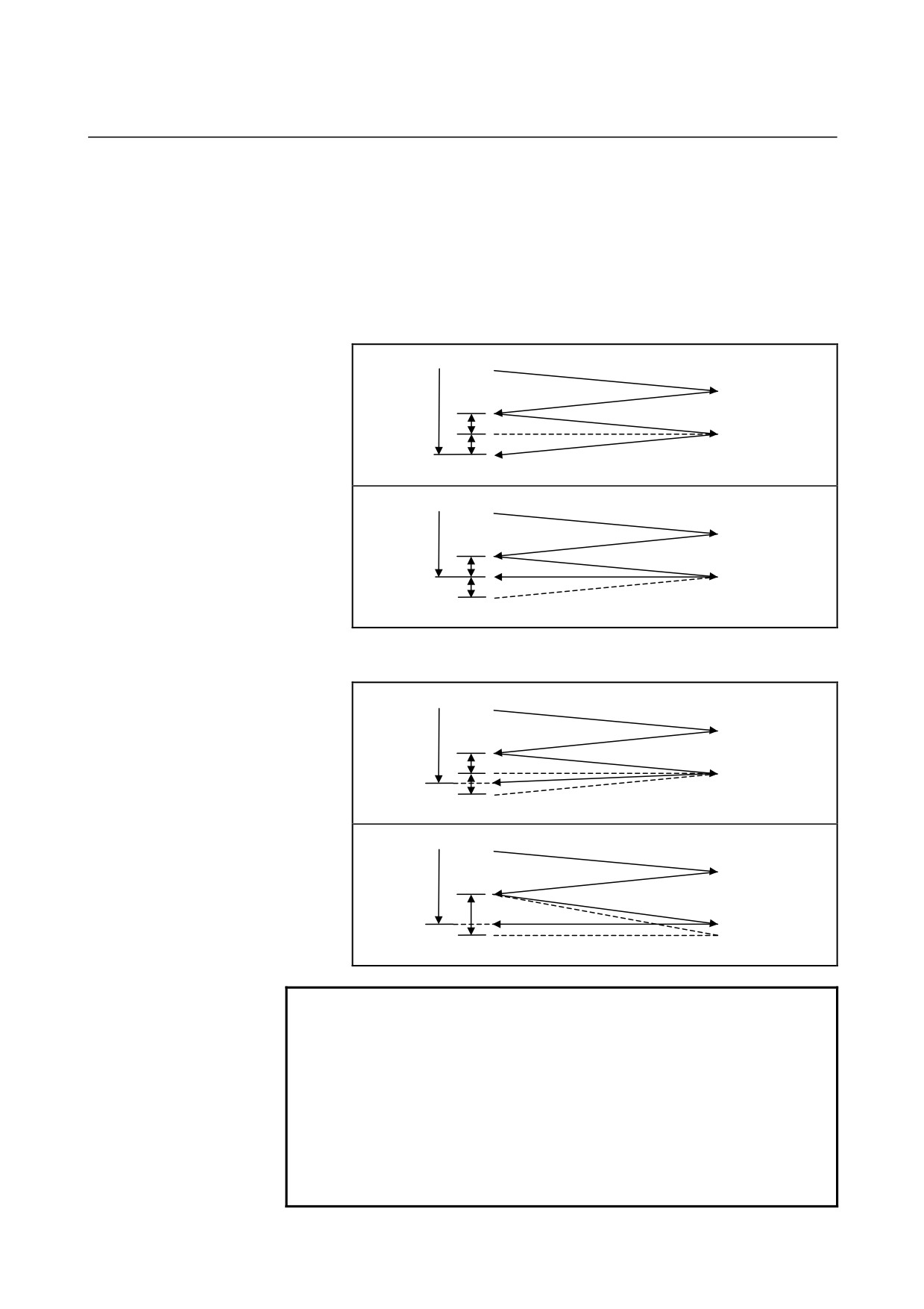
- Operation to be performed if the total depth of cut is reached
If, during cutting with I or J, the total depth of cut is reached, the cycle
is ended after the subsequent operations in the sequence (up to <4>)
are executed.
If this occurs, the depth of cut is equal to or less than the total depth of
cut.
•
If the total depth of cut is reached due to a cutting operation with
I or J
K
<1>
<2>
I
<3>
J
<4>
K
<1>
<2>
I
<3>
J
<4>
•
If the total depth of cut is reached during a cutting operation with
I or J
K
<1>
<2>
I
<3>
J
<4>
K
<1>
<2>
I
<4>
<3>
NOTE
1 If I, J, and K have different signs, alarm PS0455 is issued.
2 If G78 is specified, but a grinding axis is not specified,
alarm PS0455 is issued.
3 If any two of the cutting axis number, the grinding axis
number, and the dressing axis number are the same, alarm
PS0456 is issued.
4 While this cycle is effective, even if G90 (absolute
command) is executed, the α, I, J, and K commands are
incremental ones.
- 114 -
5.FUNCTIONS TO SIMPLIFY
B-64304EN-2/01
PROGRAMMING
PROGRAMMING
5.6.4
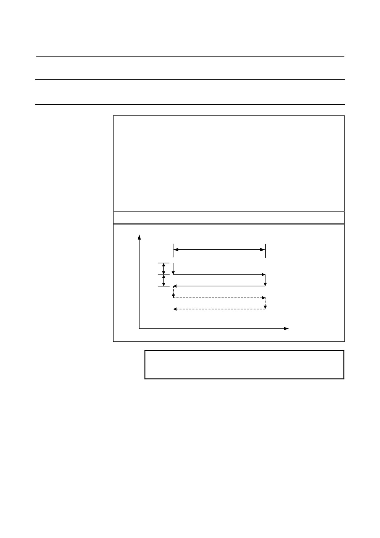
Intermittent-feed Surface Grinding Cycle (G79)
An intermittent-feed surface grinding cycle can be performed.
Format
G79 I_ J_ K_ α_ R_ F_ P_ L_ ;
I_
: First depth of cut (The cutting direction depends on the sign.)
J_
: Second depth of cut (The cutting direction depends on the sign.)
K_ : Total depth of cut (The cutting direction depends on the sign.)
α_
: Grinding range (The grinding direction depends on the sign.)
R_ : Feedrate for I and J
F_
: Feedrate for α
P_ : Dwell time
L_
: Grinding-wheel wear compensation number (during continuous
dressing only)
G79
Z
α
I
<1> (R)
<3> (F)
<2> P
<4> (R)
J
<6> (F)
<5> P
α
NOTE
α is an arbitrary axis address on the grinding axis
as determined with parameter No. 5179.
- 115 -
5. FUNCTIONS TO SIMPLIFY
PROGRAMMING
PROGRAMMING
B-64304EN-2/01
Explanation
An intermittent-feed surface grinding cycle consists of a sequence of
six operations.
Operations <1> to <6> are repeated until the depth of cut reaches the
total depth of cut specified with address K. For a single block,
operations <1> to <6> are executed with a single cycle start.
- Operation sequence in a cycle
<1> Cutting with a grinding wheel
Makes a cut in the Z-axis direction with cutting feed by the amount
specified as the first depth of cut I. The feedrate is the one specified
with R.
<2> Dwell
Performs a dwell for the time specified with P.
<3> Grinding
Causes the machine to move with cutting feed by the amount specified
with α. The grinding axis is specified with parameter No. 5179. The
feedrate is the one specified with F. If L is specified when the
continuous dressing function is enabled, dressing is performed with
the cutting axis and the dressing axis. The dressing axis is specified
with parameter No. 5183.
<4> Cutting with a grinding wheel
Makes a cut in the Z-axis direction with cutting feed by the amount
specified as the second depth of cut J. The feedrate is the one specified
with R.
<5> Dwell
Performs a dwell for the time specified with P.
<6> Grinding (return direction)
Feeds the machine at the feedrate specified with F in the opposite
direction by the amount specified with α. If L is specified when the
continuous dressing function is enabled, dressing is performed with
the cutting axis and the dressing axis.
- Continuous dressing
If the continuous dressing function is enabled, the grinding-wheel cut
and the dresser cut are continuously compensated for according to the
dressing amount specified with L during the execution of grinding.
For details, see Explanation of G75.
Limitations
- Cutting axis
The cutting axis is the third controlled axis. By setting bit 0 (FXY) of
parameter No. 5101 to 1, the axis can be switched with a plane
selection command (G17, G18, or G19).
- Grinding axis
To specify a grinding axis, set its axis number, which must be other
than that of the cutting axis, in parameter No. 5179.
- 116 -
5.FUNCTIONS TO SIMPLIFY
B-64304EN-2/01
PROGRAMMING
PROGRAMMING
- Dressing axis
To specify a dressing axis, set its axis number, which must be other
than those of the cutting axis and the grinding axis, in parameter No.
5183.
- α,I,J,K
α, I, J, and K commands are all incremental ones.
Spark-out (execution of movement in the grinding direction only)
occurs in the following cases:
•
I or J is not specified or I = J = 0
•
K is not specified or K = 0
If I or J is not specified or if I = J = 0 is true, and K is not equal to 0, a
grinding operation is performed infinitely.
- Clearing
The data items I, J, K, α, R, F, and P in a canned cycle are modal
information common to G75, G77, G78, and G79, so that once
specified, they remain effective until specified anew. The data is
cleared when a G code of group 00 other than G04 or a G code of
group 01 other than G75, G77, G78, and G79 is specified. L is
effective only in the block in which it is specified.
- Operation to be performed if the total depth of cut is reached
The operation to be performed if the total depth of cut reaches during
cutting with I or J is the same as that for G75. See Limitation on
G75.
NOTE
1 If I, J, and K have different signs, alarm PS0455 is
issued.
2 If G79 is specified, but a grinding axis is not
specified, alarm PS0455 is issued.
3 If any two of the cutting axis number, the grinding
axis number, and the dressing axis number are the
same, alarm PS0456 is issued.
4 While this cycle is effective, even if G90 (absolute
command) is executed, the α, I, J, and K
commands are incremental ones.
- 117 -
6.COMPENSATION FUNCTION
PROGRAMMING
B-64304EN-2/01
6
COMPENSATION FUNCTION
Chapter
6, "COMPENSATION FUNCTION", consists of the
following sections:
6.1 TOOL LENGTH COMPENSATION (G43, G44, G49)
119
6.2 TOOL LENGTH COMPENSATION SHIFT TYPES
127
6.3 AUTOMATIC TOOL LENGTH MEASUREMENT (G37)
137
6.4 TOOL OFFSET (G45 - G48)
141
6.5 OVERVIEW OF CUTTER COMPENSATION (G40-G42)
146
6.6 DETAILS OF CUTTER COMPENSATION
153
6.7 CORNER CIRCULAR INTERPOLATION (G39)
210
6.8 TOOL COMPENSATION VALUES, NUMBER OF
COMPENSATION VALUES, AND ENTERING VALUES
FROM THE PROGRAM (G10)
212
6.9 SCALING (G50, G51)
215
6.10 COORDINATE SYSTEM ROTATION (G68, G69)
224
6.11 NORMAL DIRECTION CONTROL (G40.1,G41.1,G42.1)
231
6.12 PROGRAMMABLE MIRROR IMAGE (G50.1, G51.1)
236
- 118 -
B-64304EN-2/01
PROGRAMMING
6.COMPENSATION FUNCTION
6.1
TOOL LENGTH COMPENSATION (G43, G44, G49)
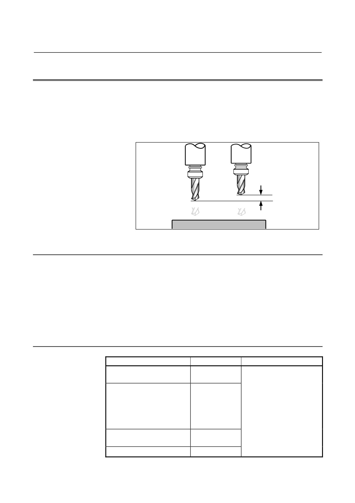
This function can be used by setting the difference between the tool
length assumed during programming and the actual tool length of the
tool used into the offset memory. It is possible to compensate the
difference without changing the program.
Specify the direction of offset with G43 or G44. Select a tool length
compensation value from the offset memory by entering the
corresponding address and number (H code).
Tool assumed
Actual tool
during programming
Specify this distance as
the value of tool length
compensation.
Fig. 6.1 (a) Tool length compensation
6.1.1
Overview
The following three methods of tool length compensation can be used,
depending on the axis along which tool length compensation can be
made.
- Tool length compensation A
Compensates for the difference in tool length along the basic Z-axis.
- Tool length compensation B
Compensates for the difference in tool length in the direction normal
to a selected plane.
- Tool length compensation C
Compensates for the difference in tool length along a specified axis.
Format
Type
Format
Description
G43 Z_ H_ ;
Tool length compensation A
G44 Z_ H_ ;
G43 : Positive offset
G44 : Negative offset
G17 G43 Z_ H_ ;
G17 : XY plane selection
G17 G44 Z_ H_ ;
G18 : ZX plane selection
G18 G43 Y_ H_ ;
Tool length compensation B
G19 : YZ plane selection
G18 G44 Y_ H_ ;
α
: Address of a specified axis
G19 G43 X_ H_ ;
H
: Address for specifying the
G19 G44 X_ H_ ;
tool length compensation
G43 α_H_ ;
value
Tool length compensation C
G44 α_H_ ;
X, Y, Z : Offset move command
Tool length compensation cancel
G49 ; or H0 ;
- 119 -
6.COMPENSATION FUNCTION
PROGRAMMING
B-64304EN-2/01
Explanation
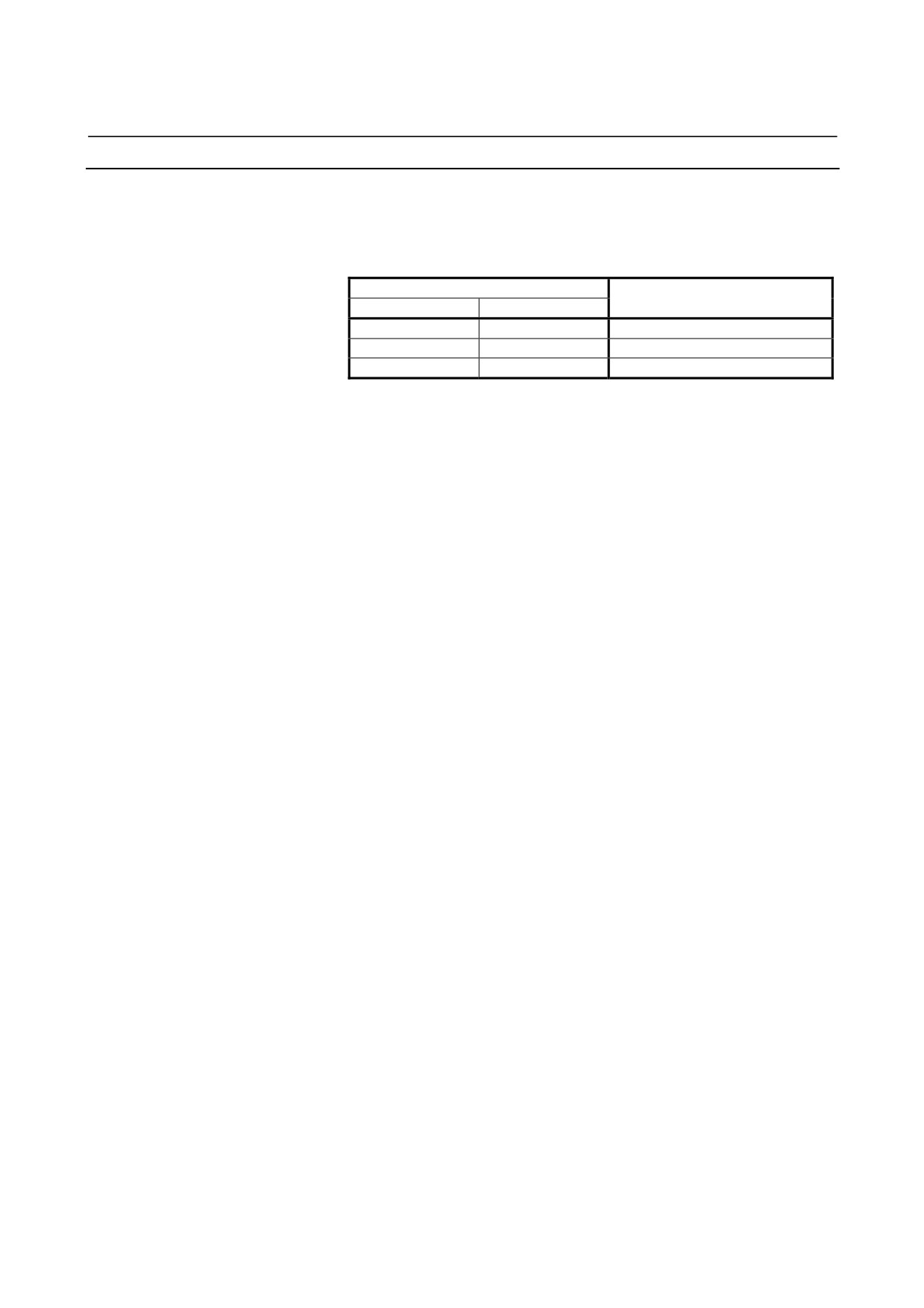
- Selection of tool length compensation
Select tool length compensation A, B, or C, by setting bits 1 (TLB)
and 0 (TLC) of parameter No.5001 .
Parameter No.5001
Type
Bit 1 (TLB)
Bit 0 (TLC)
0
0
Tool length compensation A
1
0
Tool length compensation B
0/1
1
Tool length compensation C
- Direction of the offset
When G43 is specified, the tool length compensation value (stored in
offset memory) specified with the H code is added to the coordinates
of the end position specified by a command in the program. When
G44 is specified, the same value is subtracted from the coordinates of
the end position. The resulting coordinates indicate the end position
after compensation, regardless of whether the absolute or incremental
mode is selected.
When the specification of an axis is omitted, a movement is made by
the tool length compensation value.
G43 and G44 are modal G codes. They are valid until another G code
belonging to the same group is used.
- 120 -
B-64304EN-2/01
PROGRAMMING
6.COMPENSATION FUNCTION
- Specification of the tool length compensation value
The tool length compensation value assigned to the number (offset
number) specified in the H code is selected from offset memory and
added to or subtracted from the moving command in the program.
Example
:
H1 ;
The offset value of offset number 1 is
selected.
:
G43 Z_ ; Offset is applied according to the offset
value of offset number 1.
:
H2 ;
Offset is applied according to the offset
value of offset number 2.
:
H0 ;
Offset is applied according to the offset
value 0.
:
H3 ;
Offset is applied according to the offset
value of offset number 3.
:
G49 ; Offset is canceled.
:
H4 ;
The offset value of offset number 4 is
selected.
:
A tool length compensation value is to be set in the offset memory
corresponding to an offset number.
WARNING
When another offset number is specified, the tool
length compensation value just changes to a new
value. The new tool length compensation value
is not added to the old tool length compensation
value.
H1 : Tool length compensation value 20.0
H2 : Tool length compensation value 30.0
G90 G43 Z100.0 H1 ; Z will move to 120.0
G90 G43 Z100.0 H2 ; Z will move to 130.0
NOTE
The tool length compensation value corresponding
to offset No. 0, that is, H0 always means 0. It is
impossible to set any other tool length
compensation value to H0.
- 121 -
6.COMPENSATION FUNCTION
PROGRAMMING
B-64304EN-2/01
- Performing tool length compensation along two or more axes
Tool length compensation B can be executed along two or more axes
when the axes are specified in two or more blocks.
By setting bit
3 (TAL) of parameter No. 5001 to 1, tool length
compensation C can also can be executed along two or more axes
when the axes are specified in two or more blocks. If no axis is
specified in the same block, the alarm PS0027 is issued. If two or
more axes are specified in the same block, the alarm PS0336 is issued.
Example 1
When tool length compensation B is executed
along the X-axis and Y-axis
G19 G43 H_ ;
Offset in X axis
G18 G43 H_ ;
Offset in Y axis
Example 2
When tool length compensation C is executed
along the X-axis and Y-axis
G43 X_ H_ ;
Offset in X axis
G43 Y_ H_ ;
Offset in Y axis
Example 3
When an alarm is issued with tool length
compensation C
G43 X_ Y_ H_ ; An alarm (PS0336) occurs
- Tool length compensation cancel
To cancel tool length compensation, specify G49 or H0. After G49 or
H0 is specified, the system immediately cancels the offset mode.
NOTE
1 If offset is executed along two or more axes, offset
along all axes is canceled by specifying G49. If H0
is used to specify cancellation, offset along only the
axis normal to a selected plane is canceled in the
case of tool length compensation B, or offset along
only the last axis specified by G43 or G44 is canceled
in the case of tool length compensation C.
2 If offset is executed along three or more axes, and
offset along all axes is canceled using G49, the alarm
PS0015 (TOO MANY SIMULTANEOUS AXES) may
be issued. By using H0 together, for example,
cancel offset so that the number of simultaneously
controlled axes (the number of axes along which
movements are made simultaneously) does not
exceed the allowable range of the system.
3 When H is specified as an address for setting a
compensation number in cutter compensation
(G40, G41, or G42) (bit 2 (OFH) of parameter
No.5001 = “1”), G49 (tool length compensation
cancel) is performed in the block if G49 (tool length
compensation cancel) is specified in the same block
as for G40 (cutter compensation cancel).
- 122 -
B-64304EN-2/01
PROGRAMMING
6.COMPENSATION FUNCTION
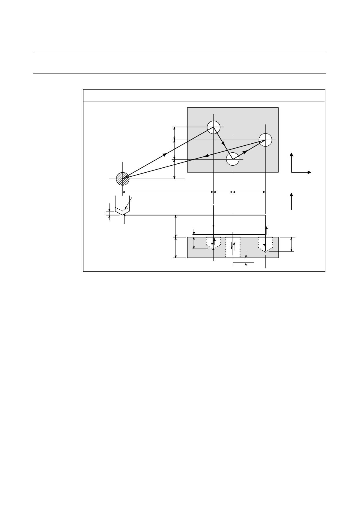
Example
Tool length compensation (in boring holes #1, #2, and #3)
#1
#3
20
(6)
30
+Y
(13)
(9)
(1)
#2
30
+X
120
30
50
+Z
Actual position
(2)
Offset value
3
Programmed
35
=4mm
(12)
position
(3)
(5)
(10)
18
(7)
22
30
(8)
(4)
(11)
8
Program
H1=-4.0 (Tool length compensation value)
N1 G91 G00 X120.0 Y80.0 ;
(1)
N2 G43 Z-32.0 H1 ;
(2)
N3 G01 Z-21.0 F1000 ;
(3)
N4 G04 P2000 ;
(4)
N5 G00 Z21.0 ;
(5)
N6 X30.0 Y-50.0 ;
(6)
N7 G01 Z-41.0 ;
(7)
N8 G00 Z41.0 ;
(8)
N9 X50.0 Y30.0 ;
(9)
N10 G01 Z-25.0 ;
(10)
N11 G04 P2000 ;
(11)
N12 G00 Z57.0 H0 ;
(12)
N13 X-200.0 Y-60.0 ;
(13)
N14 M2 ;
- 123 -
6.COMPENSATION FUNCTION
PROGRAMMING
B-64304EN-2/01
Notes
- Command for setting a workpiece coordinate system in the tool length
compensation mode
Executing a workpiece coordinate system setting G code command
(G92) presets a coordinate system in such a way that the specified
position will be a pre-compensation position.
However, this G code cannot be used together with a block where tool
length compensation vectors vary. Refer to Notes in "Work
Coordinate System Setting" of the User's Manual
(Common) for
details.
- Bit 2 (OFH) of parameter No.5001
If bit 2 (OFH) of parameter No. 5001 is set, cutter compensation takes
precedence over tool length compensation. Concrete explanations
follow:
If OFH = "0":
-
Processing is carried out properly according to a selected modal
state (G43, G44, or G49).
If OFH = "1":
-
In a block where G40, G41, or G42 is specified, tool length
compensation is disabled.
-
In the G40 mode, processing is carried out properly according to
a selected modal state (G43, G44, or G49).
-
In the G41 and G42 modes, tool length compensation is enabled
only in a block in which G43, G44, or G49 is specified. No
compensation amount is updated only with the H code.
G49 is enabled if G49 is specified in the same block as for G40,
however.
- 124 -
B-64304EN-2/01
PROGRAMMING
6.COMPENSATION FUNCTION
6.1.2
G53, G28, and G30 Commands in Tool Length Compensation
Mode
This section describes the tool length compensation cancellation and
restoration performed when G53, G28, or G30 is specified in tool
length compensation mode. Also described is the timing of tool length
compensation.
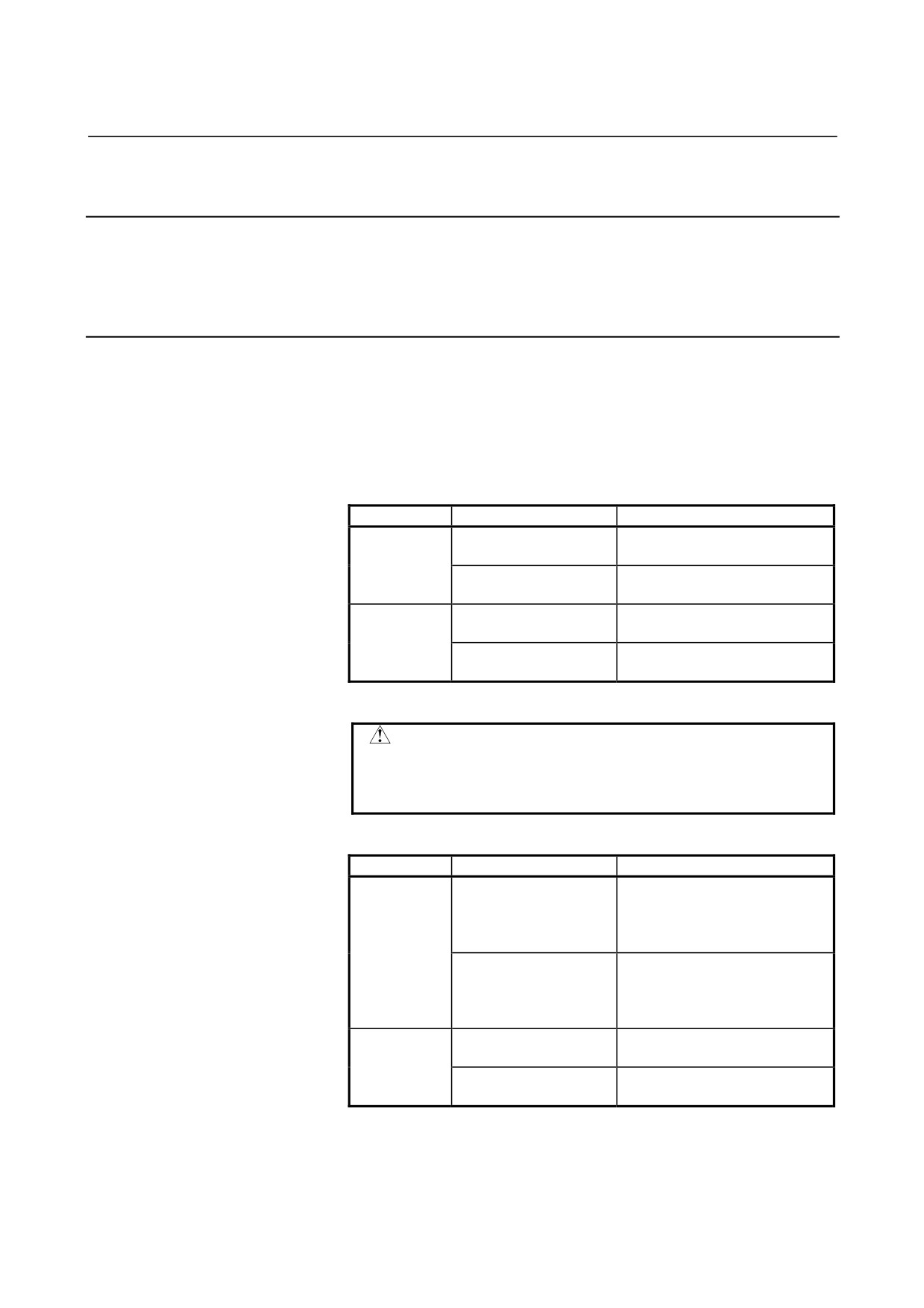
Explanation
- Tool length compensation vector cancellation
When G53, G28, or G30 is specified in tool length compensation
mode, tool length compensation vectors are canceled as described
below. However, the previously specified modal G code remains
displayed; modal code display is not switched to G49.
(1) When G53 is specified
Command
Specified axis
Operation
Tool length
Canceled upon movement being
compensation axis
performed
G53 IP_
Other than tool length
Not canceled
compensation axis
Tool length
Canceled upon movement being
compensation axis
performed
G49 G53 IP_
Other than tool length
Canceled
compensation axis
(IP_ : Dimension word)
CAUTION
If tool length compensation is applied along
multiple axes, the offset vector along the axis
specified by G53 is canceled.
(2) When G28 or G30 is specified
Command
Specified axis
Operation
Tool length
Not canceled at an intermediate
compensation axis
point.
Canceled at the reference
position.
G28 IP_
Other than tool length
Not canceled at an intermediate
compensation axis
point.
Canceled at the reference
position.
Tool length
Canceled when a movement is
compensation axis
made to an intermediate point.
G49 G28 IP_
Other than tool length
Canceled when a movement is
compensation axis
made to an intermediate point.
(IP_ : Dimension word)
- 125 -
6.COMPENSATION FUNCTION
PROGRAMMING
B-64304EN-2/01
CAUTION
If tool length compensation is applied along
multiple axes, the offset vector along the axis on
which a reference position return operation has
been performed is canceled.
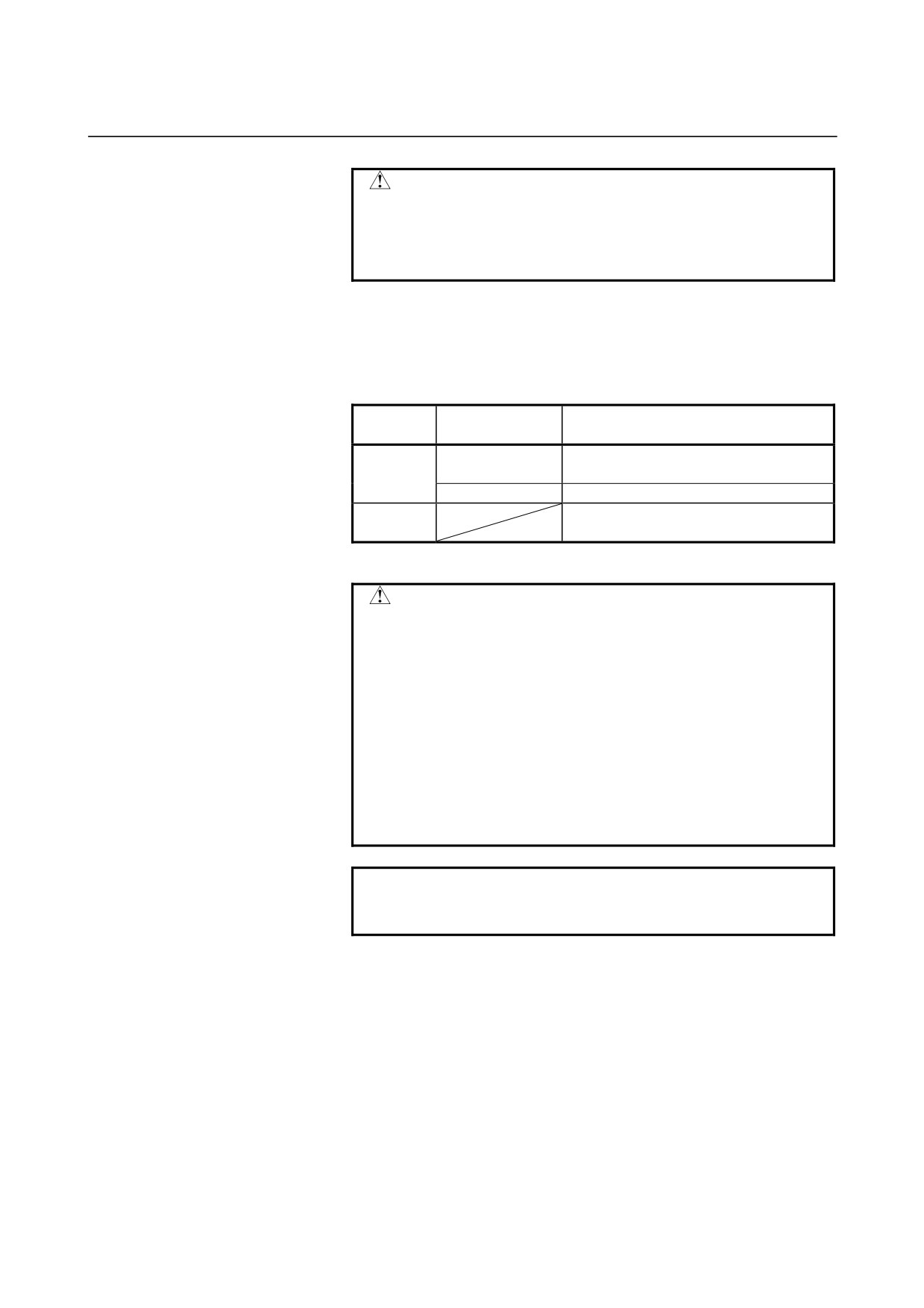
- Tool length compensation vector restoration
Tool length compensation vectors, canceled by specifying G53, G28,
or G30 in tool length compensation mode, are restored as described
below.
Parameter EVO
Type
Restoration condition
(No.5001#6)
The H command or G43 (G44) is
0
A/B
specified.
1
Restored by the next buffered block.
The H command or G43 (G44) IP_ is
C
specified.
(IP_ : Dimension word)
CAUTION
If a tool length compensation vector is restored
only with H_, G43, or G44 when tool length
compensation is applied along multiple axes, the
tool length compensation vector along only the
axis normal to a selected plane is restored in the
case of tool length compensation B, or the tool
length compensation vector along only the last axis
for which tool length compensation is specified is
restored in the case of tool length compensation C.
The tool length compensation vector along any
other axes is not restored.
NOTE
In a block in which G40, G41, or G42 is specified,
no tool length compensation vector is restored.
- 126 -
B-64304EN-2/01
PROGRAMMING
6.COMPENSATION FUNCTION
6.2
TOOL LENGTH COMPENSATION SHIFT TYPES
Overview
A tool length compensation operation can be performed by shifting
the program coordinate system: The coordinate system containing
the axis subject to tool length compensation is shifted by the tool
length compensation value. A tool length compensation shift type
can be selected with parameter TOS (parameter No. 5006#6). If no
move command is specified together with the G43, G44, or G49
command, the tool will not move along the axis. If a move command
is specified together with the G43, G44, or G49 command, the
coordinate system will be shifted first, then the tool will move along
the axis.
One of the following three methods is available, depending on the
type of axis that can be subject to tool length compensation:
•
Tool length compensation A
Compensates the value of the tool length on the Z axis.
•
Tool length compensation B
Compensates the value of the tool length on one of the X, Y, and
Z axis.
•
Tool length compensation C
Compensates the value of the tool length on a specified axis.
Format
- Tool length compensation A
G43 Z_H_;
Shifts the coordinate system along the Z axis by the
compensation value, to the + side.
G44 Z_H_;
Shifts the coordinate system along the Z axis by the
compensation value, to the - side.
G43 (or G44) : + (or -) side offset at which to start tool
length compensation
H_
: Address specifying the tool length
compensation value
- 127 -
6.COMPENSATION FUNCTION
PROGRAMMING
B-64304EN-2/01
- Tool length compensation B
G17 G43 Z_H_;
Shifts the coordinate system along the Z axis by the
compensation value, to the + side.
G17 G44 Z_H_;
Shifts the coordinate system along the Z axis by the
compensation value, to the - side.
G18 G43 Y_H_;
Shifts the coordinate system along the X axis by the
compensation value, to the + side.
G18 G44 Y_H_;
Shifts the coordinate system along the X axis by the
compensation value, to the - side.
G19 G43 X_H_;
Shifts the coordinate system along the Y axis by the
compensation value, to the + side.
G19 G44 X_H_;
Shifts the coordinate system along the Y axis by the
compensation value, to the - side.
G17 (or G18, G19)
: Plane selection
G43 (or G44)
:
+ (or -) side offset at which to start
tool length compensation
H_
: Address specifying the tool length
compensation value
- Tool length compensation C
G43 α_H_;
Shifts the coordinate system along a specified axis by the
compensation value, to the + side.
G44 α_H_;
Shifts the coordinate system along a specified axis by the
compensation value, to the - side.
G43 (or G44) : + (or -) side offset at which to start tool
length compensation
α_
: Address of any one axis
H_
: Address specifying the tool length
compensation value
- Tool length compensation cancel
G49; or H0; Tool length compensation cancel
G49 (or H0): Tool length compensation cancel
- 128 -
B-64304EN-2/01
PROGRAMMING
6.COMPENSATION FUNCTION
Explanation
- Offset direction
If the tool length compensation value specified with an H code (and
stored in offset memory) is G43, the coordinate system is shifted to
the
+ side; if G44, to the - side. If the sign of the tool length
compensation value is -, the coordinate system is shifted to the - side
if G43 and to the + side if G44. G43 and G44 are modal G codes;
they remain valid until another G code in the same group is used.
- Specifying a tool length compensation value
The tool length compensation value corresponding to the number
(offset number) specified with an H code
(and stored in offset
memory) is used. The tool length compensation corresponding to the
offset number 0 always means 0. It is not possible to set a tool
length compensation value corresponding to H0.
- Compensation axis
Specify one of tool length compensation types A, B, and C, using
parameters TLC and TLB (No. 5001#0, #1).
- Specifying offset on two or more axes
Tool length compensation B enables offset on two or more axes by
specifying offset axes in multiple blocks.
To perform offset on X and Y axes
G19 G43 H_; Performs offset on the X axis.
G18 G43 H_; Performs offset on the Y axis.
Tool length compensation C suppresses the generation of an alarm
even if offset is performed on two or more axes at the same time, by
setting TAL (No. 5001#3) to 1.
- Tool length compensation cancel
To cancel offset, specify either G49 or H0. Canceling offset causes
the shifting of the coordinate system to be undone. If no move
command is specified at this time, the tool will not move along the
axis.
- 129 -
6.COMPENSATION FUNCTION
PROGRAMMING
B-64304EN-2/01
Limitation
- Operation to be performed at the start and cancellation of tool length
compensation
When a tool length compensation shift type is used (bit 6 (TOS) of
parameter No. 5006 = 1), and if the start or cancellation (G43, G44,
G49, or H0) of a tool length compensation is specified in cutter
compensation mode (G41,G42), look-ahead of the subsequent blocks
is not performed until the end of the block in which the start or
cancellation is specified. Thus, the operation is as described below.
•
In the block in which the start or cancellation is specified,
deceleration to a stop is performed.
•
Because look-ahead is not performed, the compensation vector of
cutter compensation is vertical to the block immediately
preceding the one in which the start or cancellation is specified.
Thus, overcutting or undercutting may occur before or after this
command.
•
Until the completion of the block in which the start or
cancellation is specified, the subsequent custom macros will not
be executed.
Example in which overcutting occurs in cutter compensation)
Overcutting may occur if tool length compensation is started or
canceled in cutter compensation mode.
:
G40 G49 G00 G90 X0 Y0 Z100. ;
N1 G42 G01 X10. Y10. F500 D1 ; Start of cutter compensation
N2 G43 Z0. H2 ;
Start of tool length compensation
N3 X100. ;
N4 Y100. ;
N5 X10. ;
N6 Y10. ;
N7 G49 Z100. ;
Cancellation of tool length compensation
N8 #100=#5023 ;
Custom macro command
N9 G40 X0 Y0 ;
Cancellation of cutter compensation
:
- 130 -
B-64304EN-2/01
PROGRAMMING
6.COMPENSATION FUNCTION
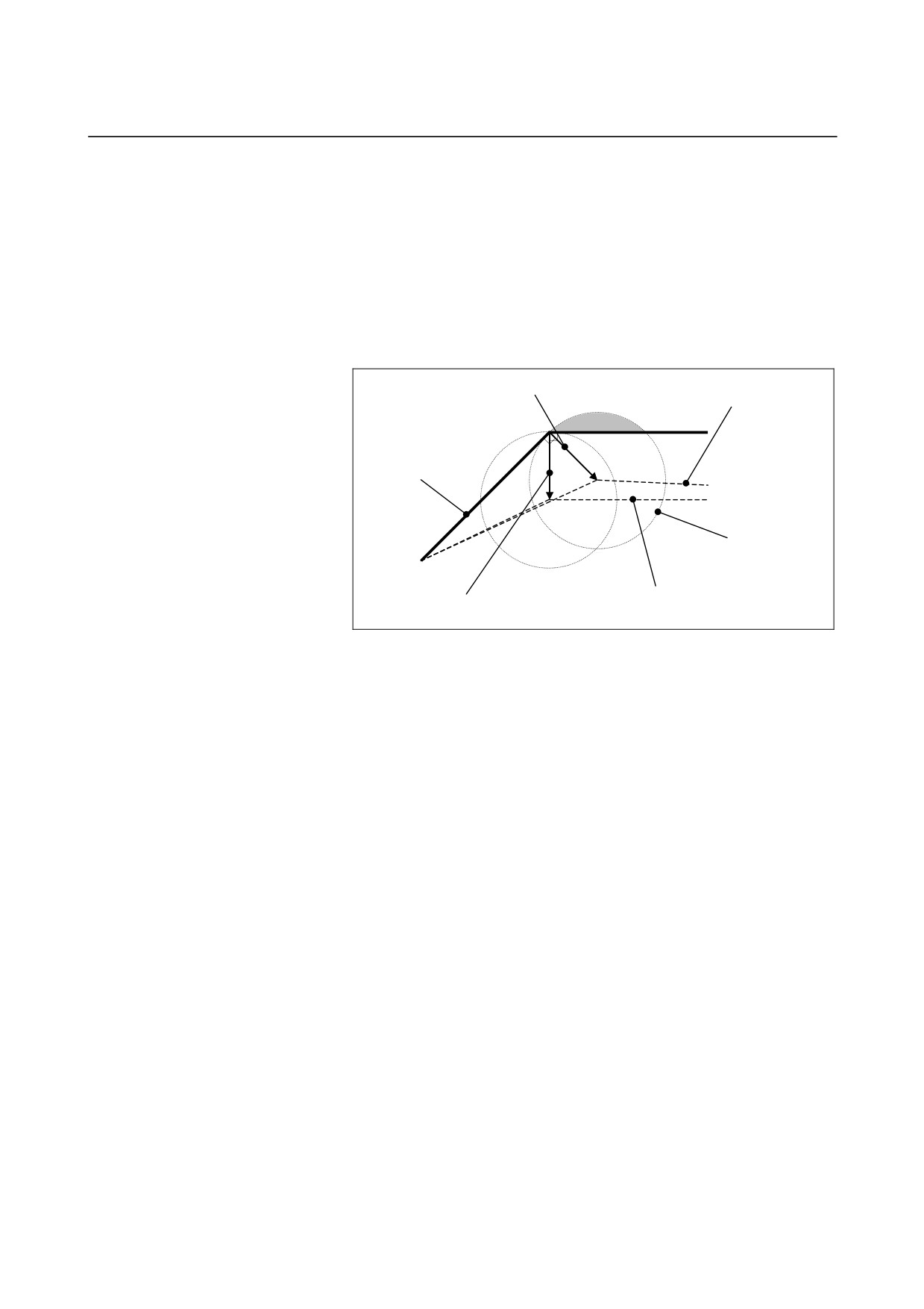
N2 contains G43
(start of tool length compensation) in cutter
compensation
(G42) mode and, therefore, look-ahead of N3 and
subsequent blocks is not performed.
As a result,
•
Deceleration to a stop is performed between N2 and N3.
•
The cutter compensation vector at the end point of N1 is vertical
to block N1. (Overcutting may occur.)
If it is assumed that look-ahead is performed, the vector is
vertical to the start point of N2, and no overcutting occurs.
Cutter compensation vector if look-ahead is not
Tool center path if look-ahead
performed
is not performed
Path specified by the
program
Tool
Tool center path if look-ahead is
Cutter compensation vector if
performed
look-ahead is performed
N7 contains G49 (cancellation of tool length compensation) in G42
mode and, therefore, look-ahead of N8 and subsequent blocks is not
performed.
As a result,
•
Deceleration to a stop is performed at the end point of N7.
•
The custom macro command in N8 is executed after the end of
N7. This means that in this example, variable #100 will be the
machine coordinate on the Z-axis at the end point position of N7.
(Variable #5023: Machine coordinate on the third axis)
If it is assumed that look-ahead is performed, N8 is executed at
the point the look-ahead of N8 is performed, that is, before the
end of N7, so that variable #100 will be a position before the end
point of N7.
•
The cutter compensation vector at the end point of N6 is vertical
to block N6. (Overcutting or undercutting may occur.)
- 131 -
6.COMPENSATION FUNCTION
PROGRAMMING
B-64304EN-2/01
Example in which no overcutting occurs in cutter compensation
(recommended)
Before cutter compensation mode, start tool length compensation.
:
G40 G49 G00 G90 X0 Y0 Z100. ;
N1 G43 G01 Z100. F500 H2 ;
Start of tool length compensation
N2 G42 X10. Y10. D1 ;
Start of cutter compensation
N3 Z0 ;
N4 X100. ;
N5 Y100. ;
N6 X10. ;
N7 Y10. ;
N8 G40 X0 Y0 ;
Cancellation of cutter compensation
N9 G49 Z100. ;
Cancellation of tool length compensation
N10 #100=#5023 ;
Custom macro command
:
N1 is a command for starting tool length compensation. However,
blocks N2 and the subsequent blocks are preread because the current
mode is not cutter compensation. As a result, the cutter compensation
path can be determined correctly. In blocks N1 and N9, deceleration
to a stop is not performed. The custom macro command in N10 is
executed without waiting for the end of N9.
Operation to be performed if the tool length compensation is changed in tool length
compensation mode
When a tool length compensation shift type is used (bit 6 (TOS) of
parameter No. 5006 = 1), it is possible to select the operation to be
performed if the tool length compensation is changed (*1) in cutter
compensation (G41,G42) and in tool length (G43,G44), by using bit 1
(MOF) of parameter No. 5000.
•
Bit 1 (MOF) of parameter No. 5000 = 0
The tool moves along the axis by the change in tool length
compensation.
•
Bit 1 (MOF) of parameter No. 5000 = 1:
After the tool length compensation is changed, movement by the
change in tool length compensation is not performed until the
absolute command for the compensation axis is executed.
*1 Changes in tool length compensation include:
-
H code specified in a program (D code for the lathe system
extended tool selection function)
-
G43/G44 specified to change the direction of tool length
compensation
-
Tool compensation amount changed using the offset screen,
G10 command, system variable, or window function when
bit 6 (EVO) of parameter No. 5001 = "1"
-
Restoration of a tool length compensation vector that was
temporarily canceled using G53, G28, or G30 during tool
length compensation
- 132 -
B-64304EN-2/01
PROGRAMMING
6.COMPENSATION FUNCTION
Example in which the tool length compensation is changed with an
H code)
The following explains the operation to be performed if the offset
number is changed in tool length compensation mode.
:
G40 G49 G00 G90 X0 Y0 Z100. ;
N1 G43 G01 Z100. F500 H2 ;
Start of tool length compensation
N2 G42 X10. Y10. D1 ;
Start of cutter compensation
N3 Z0 ;
N4 X100. ;
N5 Y100. ;
N6 H3 ;
Tool length compensation (number) change
N7 X10. ;
N8 Y10. ;
N9 G91Z-5. ;
Incremental command for the compensation axis
N10 G90 Z-5. ;
Absolute command for the compensation axis
:
In N6, a tool length compensation change (H code) is specified in
cutter compensation (G42) mode and tool length compensation (G43)
mode. The operation to be performed in this case is as described
below, depending on the setting of bit 1 (MOF) of parameter No.
5000.
•
Bit 1 (MOF) of parameter No. 5000 = 0:
In block N6, the tool moves along the axis by the change in tool
length compensation.
•
Bit 1 (MOF) of parameter No. 5000 = 1:
In block N6, no movement is performed.
Block N9 contains an incremental command and, therefore, the
movement by the tool length compensation change is not
performed. The tool moves by the travel distance specified in the
program (-5.000).
Block N10 contains the absolute command for the compensation
axis that is specified first after the tool length compensation
change and, therefore, the tool length compensation change is
reflected in this block.
- 133 -
6.COMPENSATION FUNCTION
PROGRAMMING
B-64304EN-2/01
Example in which the tool length compensation is overwritten
during operation)
The following explains the operation to be performed if continuous
operation is executed with the program below, with bit 6 (EVO) of
parameter No. 5001 being 1, and tool compensation No. 2 is changed
during the execution of N3.
:
G40 G49 G00 G90 X0 Y0 Z100. ;
N1 G43 G01 Z100. F500 H2 ;
Start of tool length compensation
N2 G42 X10. Y10. D1 ;
Start of cutter compensation
N3 Z0 ;
Change tool length compensation (No. 2) during execution
N4 X100. ;
N5 Y100. ;
N6 X10. ;
N7 Y10. ;
N8 G91Z-5. ;
Incremental command for the compensation axis
N9 G90 Z-5. ;
Absolute command for the compensation axis
:
•
Bit 1 (MOF) of parameter No. 5000 = 0:
In N6
(first buffered block after the tool compensation is
changed), the tool moves along the axis by the change in tool
length compensation.
•
Bit 1 (MOF) of parameter No. 5000 = 1:
Block N6 is the first block after the tool compensation is changed,
but this block does not contain a compensation axis command,
and the movement by the change in tool length compensation is
not performed.
Block N8 contains a compensation axis command, but the
command is an incremental one, and the movement by the
change in tool length compensation is not performed. The tool
moves by the travel distance specified in the program (-5.000).
Block N9 contains the first absolute command for the
compensation axis that is specified after the tool length
compensation is changed and, therefore, the movement by the
change in tool length compensation is performed in this block.
- 134 -
B-64304EN-2/01
PROGRAMMING
6.COMPENSATION FUNCTION
CAUTION
1
Specifying tool length compensation (a shift type)
first and then executing an incremental
programming causes the tool length compensation
value to be reflected in the coordinates only, not in
the travel distance of the machine; executing an
absolute programming causes the tool length
compensation value to be reflected in both the
movement of the machine and the coordinates.
2
If a programmable mirror image is effective, the tool
length compensation is applied in the specified
direction.
3
No scaling magnification is applied to the tool length
compensation value.
4
No coordinate system rotation is applied to the tool
length compensation value. Tool length
compensation is effective in the direction in which
the offset is applied.
5
With the WINDOW command, changing parameter
TOS during automatic operation does not cause the
tool length compensation type to be changed.
6
If offset has been performed on two or more axes
with tool length compensation B, a G49 command
causes the offset to be canceled on all axes; H0
causes the offset to be canceled only on the axis
vertical to the specified plane.
7
If the tool length compensation value is changed by
changing the offset number, this simply means that
the value is replaced by a new tool length
compensation value; it does not mean that a new
tool length compensation value is added to the old
tool length compensation.
- 135 -