FANUC Series 0i-MODEL D, Series 0i Mate-MODEL D. For Machining Center System USER’S MANUAL - page 2
2. PREPARATORY FUNCTION
(G FUNCTION)
PROGRAMMING
B-64304EN-2/01
Table 2 G code list
G code
Group
Function
G54
Workpiece coordinate system 1 selection
G54.1
Additional workpiece coordinate system selection
G55
Workpiece coordinate system 2 selection
G56
14
Workpiece coordinate system 3 selection
G57
Workpiece coordinate system 4 selection
G58
Workpiece coordinate system 5 selection
G59
Workpiece coordinate system 6 selection
G60
00
Single direction positioning
G61
Exact stop mode
G62
Automatic corner override
15
G63
Tapping mode
G64
Cutting mode
G65
00
Macro call
G66
Macro modal call
12
G67
Macro modal call cancel
G68
Coordinate system rotation mode on
16
G69
Coordinate system rotation mode off
G73
Peck drilling cycle
09
G74
Left-handed tapping cycle
G75
01
Plunge grinding cycle (for grinding machine)
G76
09
Fine boring cycle
G77
Plunge direct sizing/grinding cycle (for grinding machine)
G78
01
Continuous-feed surface grinding cycle (for grinding machine)
G79
Intermittent-feed surface grinding cycle (for grinding machine)
Canned cycle cancel
G80
09
Electronic gear box : synchronization cancellation
G80.4
Electronic gear box : synchronization cancellation
34
G81.4
Electronic gear box : synchronization start
G81
Drilling cycle or spot boring cycle
Electronic gear box : synchronization start
G82
Drilling cycle or counter boring cycle
G83
Peck drilling cycle
G84
Tapping cycle
G84.2
Rigid tapping cycle (FS10/11 format)
09
G84.3
Left-handed rigid tapping cycle (FS10/11 format)
G85
Boring cycle
G86
Boring cycle
G87
Back boring cycle
G88
Boring cycle
G89
Boring cycle
G90
Absolute programming
03
G91
Incremental programming
G91.1
Checking the maximum incremental amount specified
G92
00
Setting for workpiece coordinate system or clamp at maximum spindle speed
G92.1
Workpiece coordinate system preset
G93
Inverse time feed
G94
05
Feed per minute
G95
Feed per revolution
G96
Constant surface speed control
13
G97
Constant surface speed control cancel
- 16 -

2.PREPARATORY FUNCTION
B-64304EN-2/01
PROGRAMMING
(G FUNCTION)
Table 2 G code list
G code
Group
Function
G98
Canned cycle : return to initial level
10
G99
Canned cycle : return to R point level
G160
In-feed control cancel (for grinding machine)
20
G161
In-feed control (for grinding machine)
- 17 -
3.INTERPOLATION FUNCTION
PROGRAMMING
B-64304EN-2/01
3
INTERPOLATION FUNCTION
Chapter
3, "INTERPOLATION FUNCTION", consists of the
following sections:
3.1 SINGLE DIRECTION POSITIONING (G60)
19
3.2 THREADING (G33)
22
- 18 -
B-64304EN-2/01
PROGRAMMING
3.INTERPOLATION FUNCTION
3.1
SINGLE DIRECTION POSITIONING (G60)
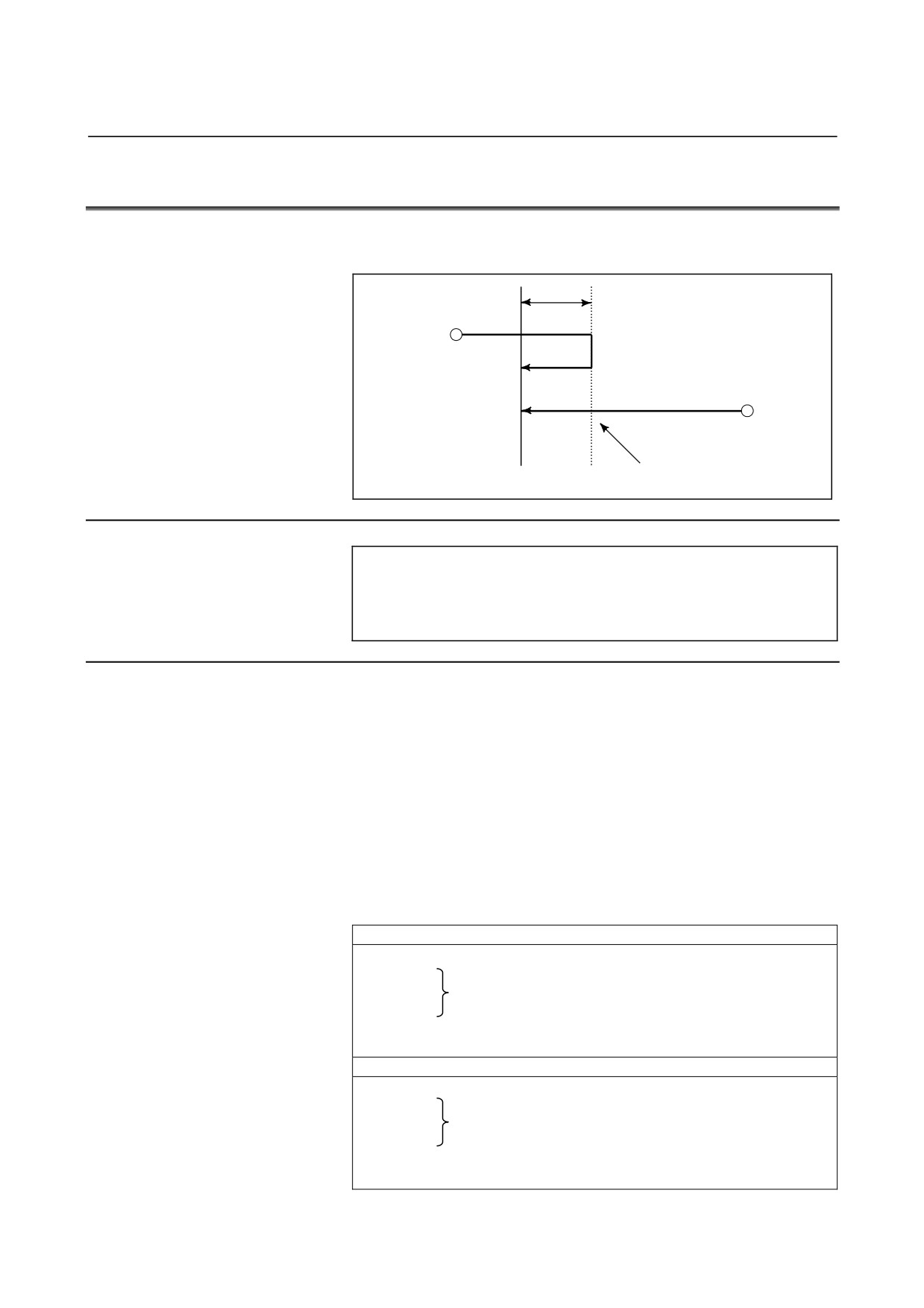
For accurate positioning without play of the machine (backlash), final
positioning from one direction is available.
Overrun
Start point
Start point
Temporary stop
End point
Format
G60 IP_ ;
IP_ : For an absolute programming, the coordinates of an
end point, and for an incremental programming, the
distance the tool moves.
Explanation
An overrun and a positioning direction are set by the parameter No.
5440. Even when a commanded positioning direction coincides with
that set by the parameter, the tool stops once before the end point.
G60, which is a one-shot G-code, can be used as a modal G-code in
group 01 by setting 1 to the bit 0 (MDL) of parameter No. 5431.
This setting can eliminate specifying a G60 command for every block.
Other specifications are the same as those for a one-shot G60
command. When a one-shot G code is specified in the single direction
positioning mode, the one-shot G command is effective like G codes
in group 01.
(Example)
When one-shot G60 commands are used.
G90;
G60 X0Y0;
G60 X100;
Single direction positioning
G60 Y100;
G04 X10;
G00 X0Y0;
When modal G60 command is used.
G90G60;
Single direction positioning mode start
X0Y0;
X100;
Single direction positioning
Y100;
G04X10;
G00X0 Y0;
Single direction positioning mode cancel
- 19 -
3.INTERPOLATION FUNCTION
PROGRAMMING
B-64304EN-2/01
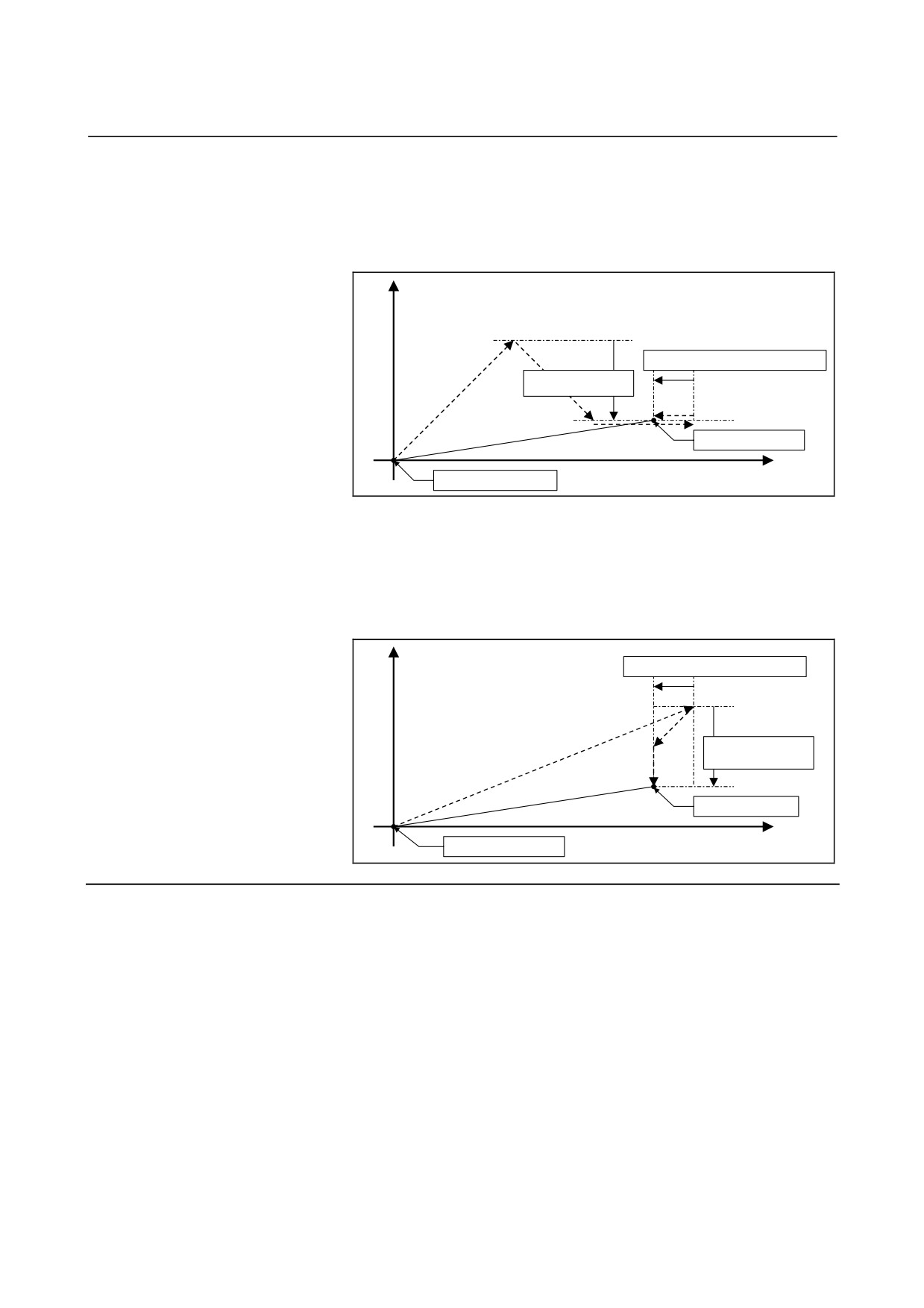
- Overview of operation
•
In the case of positioning of non-linear interpolation type (bit
1 (LRP) of parameter No. 1401 = 0)
As shown below, single direction positioning is performed
independently along each axis.
X
Overrun distance in the Z-axis direction
Overrun distance in the
X-axis direction
Programmed end point
Z
Programmed start point
•
In the case of positioning of linear interpolation type (bit 1
(LRP) of parameter No. 1401 = 1)
Positioning of interpolation type is performed until the tool once
stops before or after a specified end point. Then, the tool is
positioned independently along each axis until the end point is
reached.
X
Overrun distance in the Z-axis direction
Overrun distance in the
X-axis direction
Programmed end point
Z
Programmed start point
Limitation
• Single direction positioning is not performed along an axis for
which no overrun distance is set in parameter No. 5440.
• Single direction positioning is not performed along an axis for
which travel distance 0 is specified.
• The mirror image function is not applied in a parameter-set
direction. Even in the mirror image mode, the direction of single
direction positioning remains unchanged. If positioning of linear
interpolation type is used, and the state of mirror image when a
single direction positioning block is looked ahead differs from
the state of mirror image when the execution of the block is
started, an alarm is issued. When switching mirror image in the
middle of a program, disable looking ahead by specifying a
non-buffering M code. Then, switch mirror image when there is
no look-ahead block.
- 20 -
B-64304EN-2/01
PROGRAMMING
3.INTERPOLATION FUNCTION
• In the cylindrical interpolation mode (G07.1), single direction
positioning cannot be used.
• When specifying single direction positioning on a machine that
uses arbitrary angular axis control, first position the angular axis
then specify the positioning of the Cartesian axis. If the reverse
specification order is used, or the angular axis and Cartesian axis
are specified in the same block, an incorrect positioning direction
can result.
•
In positioning at a restart position by program restart function,
single direction positioning is not performed.
•
During canned cycle for drilling, no single direction positioning
is effected in drilling axis.
•
The single direction positioning does not apply to the shift
motion in the canned cycles of G76 and G87.
- 21 -
3.INTERPOLATION FUNCTION
PROGRAMMING
B-64304EN-2/01
3.2
THREADING (G33)
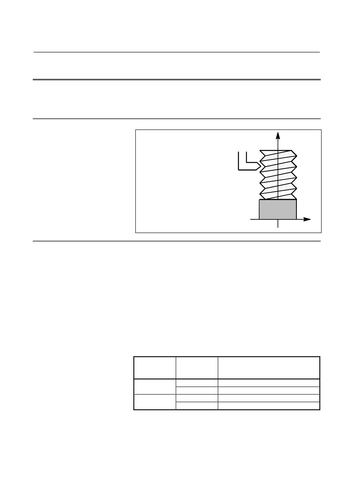
Straight threads with a constant lead can be cut. The position coder
mounted on the spindle reads the spindle speed in real-time. The read
spindle speed is converted to the feedrate per minute to feed the tool.
Format
Z
G33IP_ F_ ;
F : Long axis direction lead
Workpiece
X
Explanation
In general, threading is repeated along the same tool path in rough
cutting through finish cutting for a screw. Since threading starts
when the position coder mounted on the spindle outputs a 1-turn
signal, threading is started at a fixed point and the tool path on the
workpiece is unchanged for repeated threading. Note that the spindle
speed must remain constant from rough cutting through finish cutting.
If not, incorrect thread lead will occur.
In general, the lag of the servo system, etc. will produce somewhat
incorrect leads at the starting and ending points of a thread cut. To
compensate for this, a threading length somewhat longer than required
should be specified.
Table 3.2 (a) lists the ranges for specifying the thread lead.
Table 3.2 (a) Ranges of lead sizes that can be specified
Least
command
Command value range of the lead
increment
0.001 mm
F1 to F50000 (0.01 to 500.00mm)
Metric input
0.0001 mm
F1 to F50000 (0.01 to 500.00mm)
0.0001 inch
F1 to F99999 (0.0001 to 9.9999inch)
Inch input
0.00001 inch
F1 to F99999 (0.0001 to 9.9999inch)
- 22 -
B-64304EN-2/01
PROGRAMMING
3.INTERPOLATION FUNCTION
NOTE
1 The spindle speed is limited as follows :
1 ≤ spindle speed ≤ (Maximum feedrate) / (Thread
lead)
Spindle speed : min-1
Thread lead : mm or inch
Maximum feedrate : mm/min or inch/min ; maximum
command-specified feedrate for feed-per-minute
mode or maximum feedrate that is determined
based on mechanical restrictions including those
related to motors, whichever is smaller
2 Cutting feedrate override is not applied to the
converted feedrate in all machining process from
rough cutting to finish cutting. The feedrate is fixed
at 100%
3 The converted feedrate is limited by the upper
feedrate specified.
4 Feed hold is disabled during threading. Pressing the
feed hold key during threading causes the machine
to stop at the end point of the next block after
threading (that is, after the G33 mode is terminated)
Example
Threading at a pitch of 1.5mm
G33 Z10. F1.5;
- 23 -
4. COORDINATE VALUE AND
DIMENSION
PROGRAMMING
B-64304EN-2/01
4
COORDINATE VALUE AND DIMENSION
Chapter 4, "COORDINATE VALUE AND DIMENSION", consists
of the following sections:
4.1 POLAR COORDINATE COMMAND (G15, G16)
25
- 24 -
4.COORDINATE VALUE AND
B-64304EN-2/01
PROGRAMMING
DIMENSION
4.1
POLAR COORDINATE COMMAND (G15, G16)
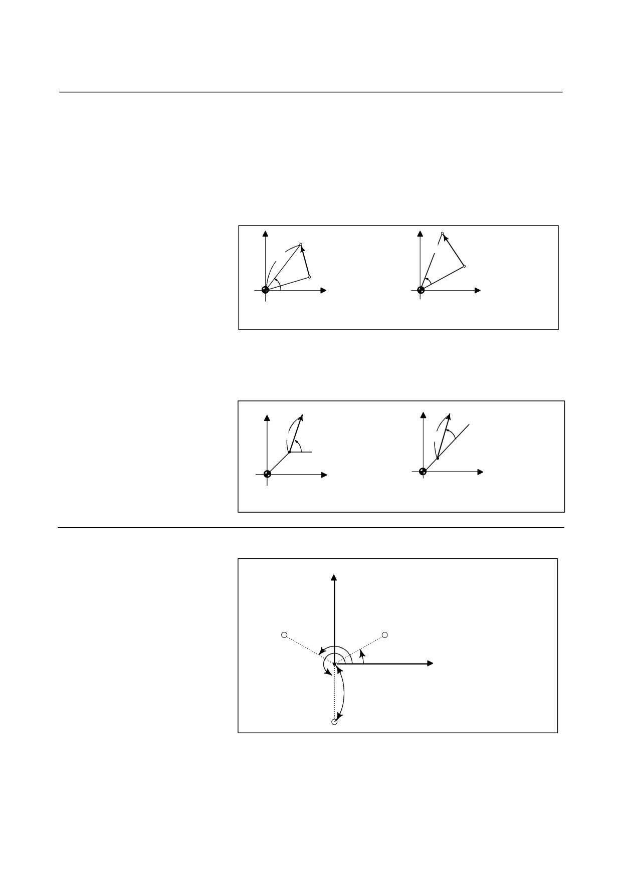
The end point coordinate value can be input in polar coordinates
(radius and angle).
The plus direction of the angle is counterclockwise of the selected
plane first axis + direction, and the minus direction is clockwise.
Both radius and angle can be commanded in either absolute or
incremental programming (G90, G91).
Format
Gxx Gyy G16; Starting the polar coordinate
command (polar coordinate mode)
G00 IP_ ;
:
Polar coordinate command
:
G15;
Canceling the polar coordinate
command (polar coordinate mode)
G16
: Polar coordinate command
G15
: Polar coordinate command cancel
Gxx
: Plane selection of the polar coordinate command
(G17, G18 or G19)
Gyy
: Center selection of the polar coordinate command
(G90 or G91)
G90 specifies the origin of the workpiece coordinate
system as the origin of the polar coordinate system,
from which a radius is measured.
G91 specifies the current position as the origin of the
polar coordinate system, from which a radius is
measured.
IP_
: Specifying the addresses of axes constituting the
plane selected for the polar coordinate system, and
their values
First axis : radius of polar coordinate
Second axis : angle of polar coordinate
- 25 -
4. COORDINATE VALUE AND
DIMENSION
PROGRAMMING
B-64304EN-2/01
- Setting the origin of the workpiece coordinate system as the origin of the polar
coordinate system
Specify the radius (the distance between the origin and the point) to be
programmed with an absolute programming. The origin of the
workpiece coordinate system is set as the origin of the polar
coordinate system.
When a local coordinate system (G52) is used, the origin of the local
coordinate system becomes the center of the polar coordinates.
Command position
Command position
Radius
Radius
Angle
Actual position
Angle
Actual position
When the angle is specified with an
When the angle is specified with an
absolute command
incremental command
- Setting the current position as the origin of the polar coordinate system
Specify the radius (the distance between the current position and the
point) to be programmed with an incremental programming. The
current position is set as the origin of the polar coordinate system.
Command position
Command position
Angle
Radius Angle
Radius
Actual position
Actual position
When the angle is specified with an
When the angle is specified with an
absolute command
incremental command
Example
Bolt hole circle
Y
- The origin of the workpiece coordinate
system is set as the origin of the polar
coordinate system.
- The XY plane is selected.
150°
30°
X
270°
100mm
- 26 -
4.COORDINATE VALUE AND
B-64304EN-2/01
PROGRAMMING
DIMENSION
- Specifying angles and a radius with absolute programmings
N1 G17 G90 G16 ; Specifying the polar coordinate command and
selecting the XY plane
Setting the origin of the workpiece coordinate
system as the origin of the polar coordinate
system
N2 G81 X100.0 Y30.0 Z-20.0 R-5.0 F200.0 ;
Specifying a distance of 100 mm and an angle
of 30 degrees
N3 Y150.0 ;
Specifying a distance of 100 mm and an angle
of 150 degrees
N4 Y270.0 ;
Specifying a distance of 100 mm and an angle
of 270 degrees
N5 G15 G80 ;
Canceling the polar coordinate command
- Specifying angles with incremental programmings and a radius with absolute
programmings
N1 G17 G90 G16; Specifying the polar coordinate command and
selecting the XY plane
Setting the origin of the workpiece coordinate
system as the origin of the polar coordinate
system
N2 G81 X100.0 Y30.0 Z-20.0 R-5.0 F200.0 ;
Specifying a distance of 100 mm and an angle
of 30 degrees
N3 G91 Y120.0 ;
Specifying a distance of 100 mm and an angle
of +120 degrees
N4 Y120.0 ;
Specifying a distance of 100 mm and an angle
of +120 degrees
N5 G15 G80 ;
Canceling the polar coordinate command
Limitation
- Specifying a radius in the polar coordinate mode
In the polar coordinate mode, specify a radius for circular
interpolation or helical interpolation (G02, G03) with R.
- Axes that are not considered part of a polar coordinate command in the polar
coordinate mode
Axes specified for the following commands are not considered part of
the polar coordinate command:
• Dwell (G04)
• Programmable data input (G10)
• Local coordinate system setting (G52)
• Workpiece coordinate system setting (G92)
• Machine coordinate system setting (G53)
• Stored stroke check (G22)
• Coordinate system rotation (G68)
• Scaling (G51)
- Optional chamfering and corner R
Optional chamfering and corner R cannot be specified in polar
coordinate mode.
- 27 -
5. FUNCTIONS TO SIMPLIFY
PROGRAMMING
PROGRAMMING
B-64304EN-2/01
5
FUNCTIONS TO SIMPLIFY
PROGRAMMING
Chapter
5, "FUNCTIONS TO SIMPLIFY PROGRAMMING",
consists of the following sections:
5.1 CANNED CYCLE FOR DRILLING
29
5.2 RIGID TAPPING
74
5.3 OPTIONAL CHAMFERING AND CORNER R
90
5.4 INDEX TABLE INDEXING FUNCTION
94
5.5 IN-FEED CONTROL (FOR GRINDING MACHINE)
97
5.6 CANNED GRINDING CYCLE
(FOR GRINDING MACHINE)
101
- 28 -
5.FUNCTIONS TO SIMPLIFY
B-64304EN-2/01
PROGRAMMING
PROGRAMMING
5.1
CANNED CYCLE FOR DRILLING
Overview
Canned cycles for drilling make it easier for the programmer to create
programs. With a canned cycle, a frequently-used machining
operation can be specified in a single block with a G function; without
canned cycles, normally more than one block is required. In addition,
the use of canned cycles can shorten the program to save memory.
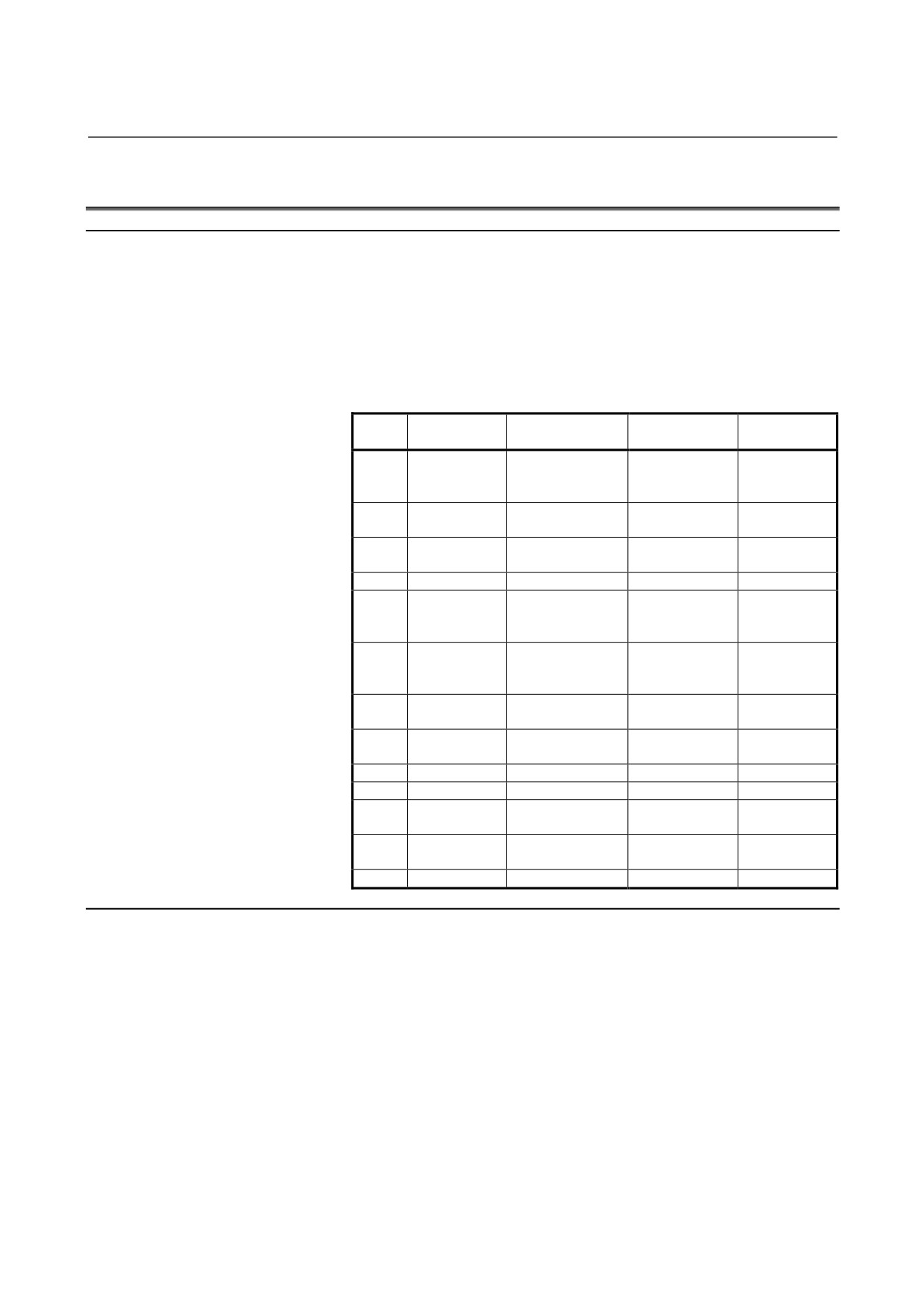
Table 5.1 (a) lists canned cycles for drilling.
Table 5.1 (a) Canned cycles for drilling
Drilling
Operation at the
Retraction
G code
Application
(-Z direction)
bottom of a hole
(+Z direction)
High-speed
Intermittent
G73
-
Rapid traverse
peck drilling
feed
cycle
Dwell →
Left-hand
G74
Feed
Feed
Spindle CW
tapping cycle
Oriented spindle
Fine boring
G76
Feed
Rapid traverse
stop
cycle
G80
-
-
-
Cancel
Drilling cycle,
G81
Feed
-
Rapid traverse
spot drilling
cycle
Drilling cycle,
G82
Feed
Dwell
Rapid traverse
counter boring
cycle
Intermittent
Peck drilling
G83
-
Rapid traverse
feed
cycle
Dwell →
G84
Feed
Feed
Tapping cycle
Spindle CCW
G85
Feed
-
Feed
Boring cycle
G86
Feed
Spindle stop
Rapid traverse
Boring cycle
Back boring
G87
Feed
Spindle CW
Rapid traverse
cycle
Dwell →
G88
Feed
Manual
Boring cycle
Spindle stop
G89
Feed
Dwell
Feed
Boring cycle
Explanation
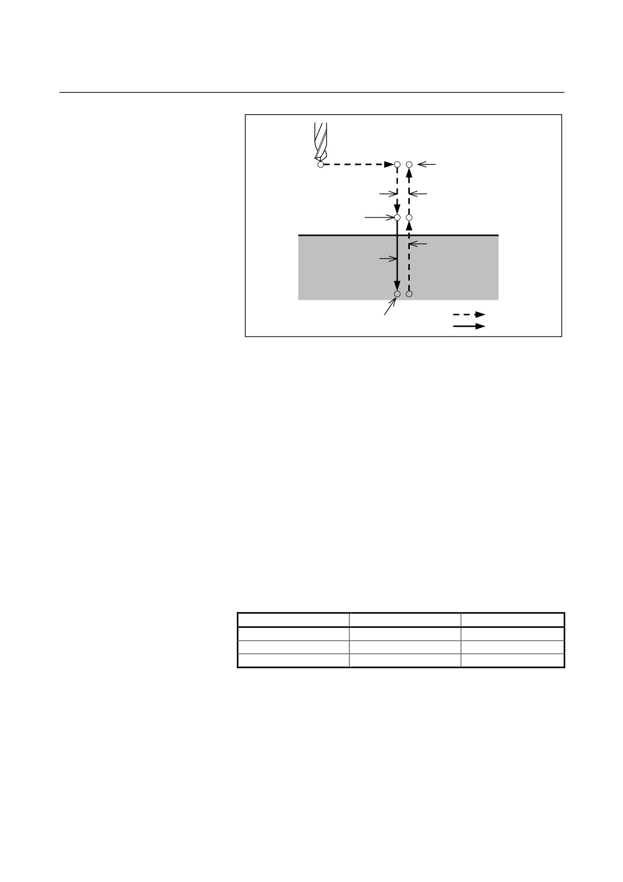
A canned cycle for drilling consists of a sequence of six operations.
Operation 1
Positioning of axes X and Y
(including also
another axis)
Operation 2
Rapid traverse up to point R level
Operation 3
Hole machining
Operation 4
Operation at the bottom of a hole
Operation 5
Retraction to point R level
Operation 6
Rapid traverse up to the initial point
- 29 -
5. FUNCTIONS TO SIMPLIFY
PROGRAMMING
PROGRAMMING
B-64304EN-2/01
Operation 1
Initial level
Operation 2
Operation 6
Point R level
Operation 5
Operation 3
Rapid traverse
Operation 4
Feed
Fig. 5.1 (a) Operation sequence of canned cycle for drilling
- Positioning plane
The positioning plane is determined by plane selection code G17, G18,
or G19.
The positioning axis is an axis other than the drilling axis.
- Drilling axis
Although canned cycles for drilling include tapping and boring cycles
as well as drilling cycles, in this chapter, only the term drilling will be
used to refer to operations implemented with canned cycles.
The drilling axis is a basic axis (X, Y, or Z) not used to define the
positioning plane, or any axis parallel to that basic axis.
The axis (basic axis or parallel axis) used as the drilling axis is
determined according to the axis address for the drilling axis specified
in the same block as G codes G73 to G89.
If no axis address is specified for the drilling axis, the basic axis is
assumed to be the drilling axis.
Table 5.1 (b) Positioning plane and drilling axis
G code
Positioning plane
Drilling axis
G17
Xp-Yp plane
Zp
G18
Zp-Xp plane
Yp
G19
Yp-Zp plane
Xp
Xp: X axis or an axis parallel to the X axis
Yp: Y axis or an axis parallel to the Y axis
Zp: Z axis or an axis parallel to the Z axis
- 30 -
5.FUNCTIONS TO SIMPLIFY
B-64304EN-2/01
PROGRAMMING
PROGRAMMING
Example
Assume that the U, V and W axes be parallel to the X, Y, and Z axes
respectively. This condition is specified by parameter No. 1022.
G17 G81 Z_ _
: The Z axis is used for drilling.
G17 G81 W_ _ : The W axis is used for drilling.
G18 G81 Y_ _ : The Y axis is used for drilling.
G18 G81 V_ _ : The V axis is used for drilling.
G19 G81 X_ _ : The X axis is used for drilling.
G19 G81 U_ _ : The U axis is used for drilling.
G17 to G19 may be specified in a block in which any of G73 to
G89 is not specified.
CAUTION
Switch the drilling axis after canceling a canned
cycle for drilling.
NOTE
A parameter FXY (No. 5101 #0) can be set to the Z
axis always used as the drilling axis. When
FXY=0, the Z axis is always the drilling axis.
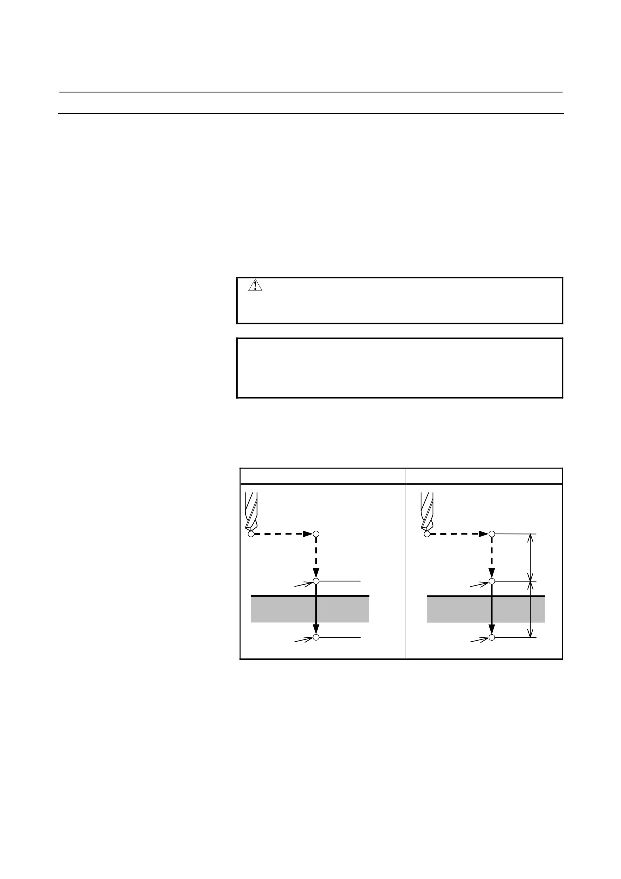
- Travel distance along the drilling axis G90/G91
The travel distance along the drilling axis varies for G90 and G91 as
follows:
G90 (Absolute programming)
G91 (Incremental programming)
R
R
Point R
Point R
Z = 0
Z
Point Z
Z
Point Z
Fig. 5.1 (b) Absolute programming and incremental programming
- Drilling mode
G73, G74, G76, and G81 to G89 are modal G codes and remain in
effect until canceled. When in effect, the current state is the drilling
mode.
Once drilling data is specified in the drilling mode, the data is retained
until modified or canceled.
Specify all necessary drilling data at the beginning of canned cycles;
when canned cycles are being performed, specify data modifications
only.
- 31 -
5. FUNCTIONS TO SIMPLIFY
PROGRAMMING
PROGRAMMING
B-64304EN-2/01
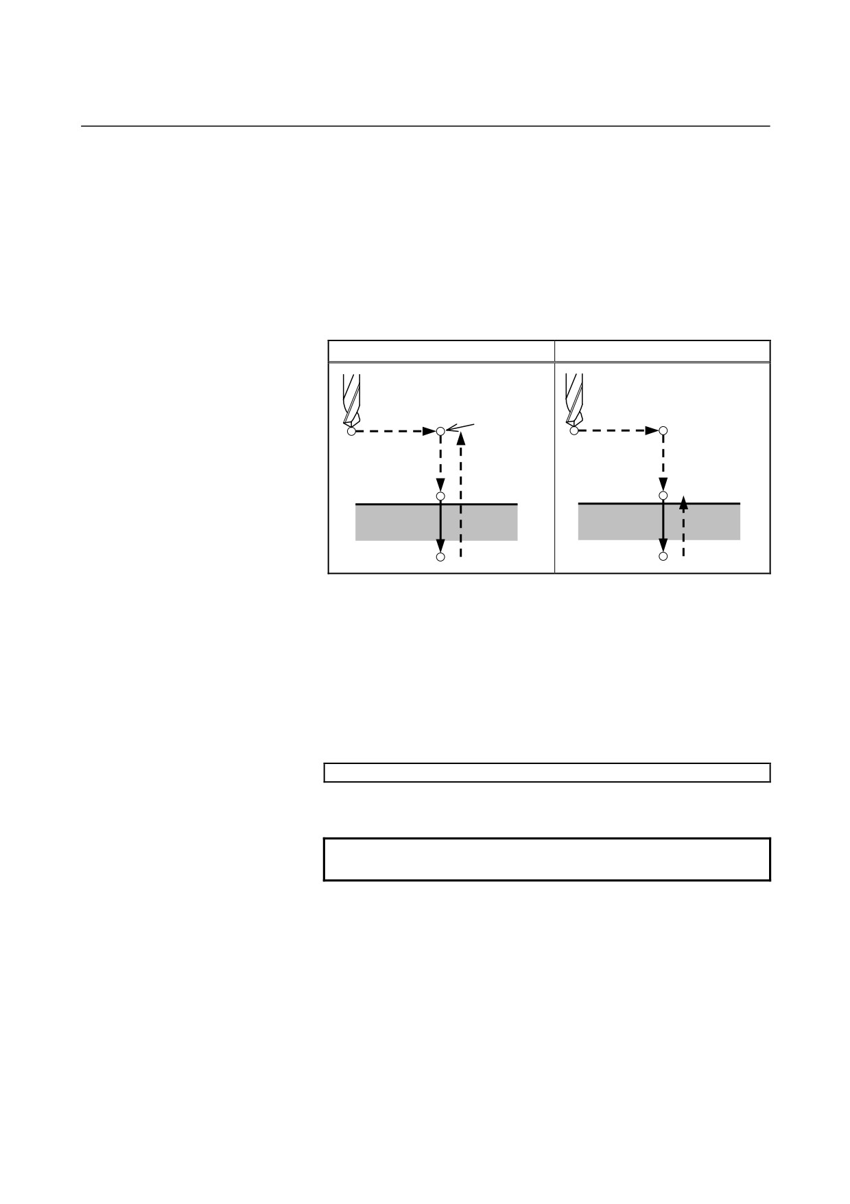
- Return point level G98/G99
When the tool reaches the bottom of a hole, the tool may be returned
to point R or to the initial level. These operations are specified with
G98 and G99. The following illustrates how the tool moves when
G98 or G99 is specified. Generally, G99 is used for the first drilling
operation and G98 is used for the last drilling operation.
The initial level does not change even when drilling is performed in
the G99 mode.
G98 (Return to initial level)
G99 (Return to point R level)
Initial level
Point R level
Fig. 5.1 (c) Initial level and point R level
- Repeat
To repeat drilling for equally-spaced holes, specify the number of
repeats in K_.
K is effective only within the block where it is specified.
Specify the first hole position in incremental programming (G91).
If it is specified in absolute programming (G90), drilling is repeated at
the same position.
Number of repeats K
The maximum command value = 9999
If K0 is specified, drilling data is stored, but drilling is not performed.
NOTE
For K, specify an integer of 0 or 1 to 9999.
- Single block
If a drilling cycle is performed in a single block, the control unit stops
at each of the end points of operations 1, 2, and 6 in Figure 5.1 (a).
This means that three starts are made to make a single hole. At the end
points of operations 1 and 2, the feed hold lamp turns on and the
control unit stops. If the repetitive count is not exhausted at the end
point of operation 6, the control unit stops in the feed hold mode, and
otherwise, stops in the single block stop mode. Note that G87 does not
cause a stop at point R in G87. G88 causes a stop at point Z after a
dwell.
- 32 -
5.FUNCTIONS TO SIMPLIFY
B-64304EN-2/01
PROGRAMMING
PROGRAMMING
- Cancel
To cancel a canned cycle, use G80 or a group 01 G code.
Group 01 G codes
G00 : Positioning (rapid traverse)
G01 : Linear interpolation
G02 : Circular interpolation or helical interpolation (CW)
G03 : Circular interpolation or helical interpolation (CCW)
G60 : Single directional positioning (if bit 0 (MDL) of parameter No.
5431 is "1")
- Symbols in figures+
Subsequent sections explain the individual canned cycles. Figures in
these Explanation use the following symbols:
Positioning (rapid traverse G00)
Cutting feed (linear interpolation G01)
Manual feed
Oriented spindle stop
OSS
(The spindle stops at a fixed rotation position)
Shift (rapid traverse G00)
P
Dwell
- 33 -
5. FUNCTIONS TO SIMPLIFY
PROGRAMMING
PROGRAMMING
B-64304EN-2/01
5.1.1
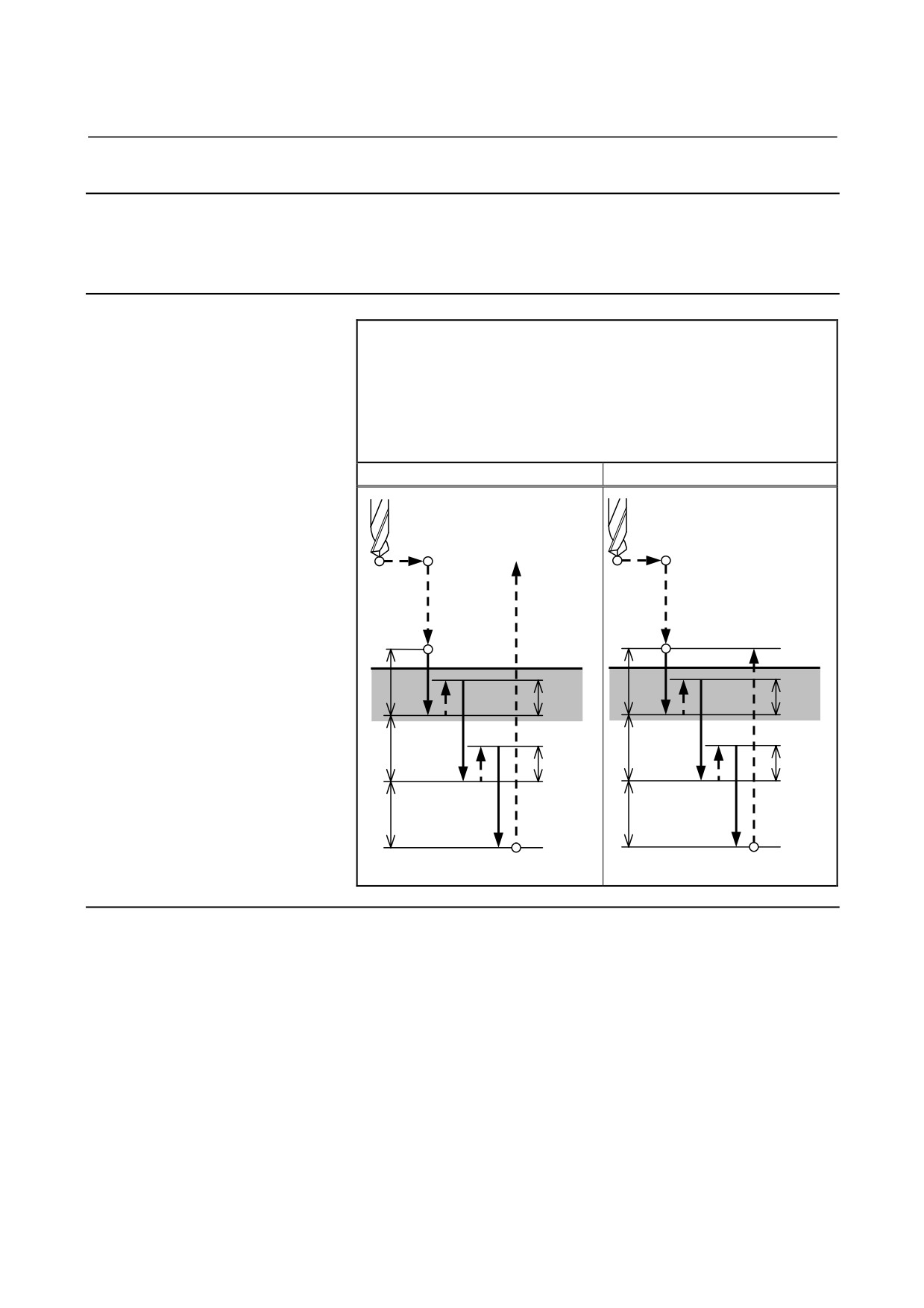
High-Speed Peck Drilling Cycle (G73)
This cycle performs high-speed peck drilling.
It performs
intermittent cutting feed to the bottom of a hole while removing chips
from the hole.
Format
G73 X_ Y_ Z_ R_ Q_ F_ K_ ;
X_ Y_ : Hole position data
Z_
: The distance from point R to the bottom of the hole
R_
: The distance from the initial level to point R level
Q_
: Depth of cut for each cutting feed
F_
: Cutting feedrate
K_
: Number of repeats (if required)
G73 (G98)
G73 (G99)
Initial level
Point R
Point R
Point R level
q
q
d
d
q
q
d
d
q
q
Point Z
Point Z
Explanation
- Operations
The high-speed peck drilling cycle performs intermittent feeding
along the Z-axis. When this cycle is used, chips can be removed
from the hole easily, and a smaller value can be set for retraction.
This allows, drilling to be performed efficiently. Set the clearance, d,
in parameter 5114.
The tool is retracted in rapid traverse.
- Spindle rotation
Before specifying G73, rotate the spindle using an auxiliary function
(M code).
- 34 -
5.FUNCTIONS TO SIMPLIFY
B-64304EN-2/01
PROGRAMMING
PROGRAMMING
- Auxiliary function
When the G73 code and an M code are specified in the same block,
the M code is executed at the time of the first positioning operation.
When K is used to specify the number of repeats, the M code is
executed for the first hole only; for the second and subsequent holes,
the M code is not executed.
- Tool length compensation
When a tool length compensation (G43, G44, or G49) is specified in
the canned cycle for drilling, the offset is applied after the time of
positioning to point R.
Limitation
- Axis switching
Before the drilling axis can be changed, the canned cycle for drilling
must be canceled.
- Drilling
In a block that does not contain X, Y, Z, R, or any other axes, drilling
is not performed.
- Q
Specify Q in blocks that perform drilling. If they are specified in a
block that does not perform drilling, they cannot be stored as modal
data.
- Cancel
Do not specify a G code of the 01 group (G00 to G03) and G73 in a
single block. Otherwise, G73 will be canceled.
- Tool offset
In the canned cycle mode for drilling, tool offsets are ignored.
Example
M3 S2000 ;
Cause the spindle to start rotating.
G90 G99 G73 X300. Y-250. Z-150. R-100. Q15. F120. ;
Position, drill hole 1, then return to point R.
Y-550. ;
Position, drill hole 2, then return to point R.
Y-750. ;
Position, drill hole 3, then return to point R.
X1000. ;
Position, drill hole 4, then return to point R.
Y-550. ;
Position, drill hole 5, then return to point R.
G98 Y-750. ;
Position, drill hole 6, then return to the initial level.
G80 G28 G91 X0 Y0 Z0 ; Return to the reference position
M5 ;
Cause the spindle to stop rotating.
- 35 -
5. FUNCTIONS TO SIMPLIFY
PROGRAMMING
PROGRAMMING
B-64304EN-2/01
5.1.2
Left-Handed Tapping Cycle (G74)
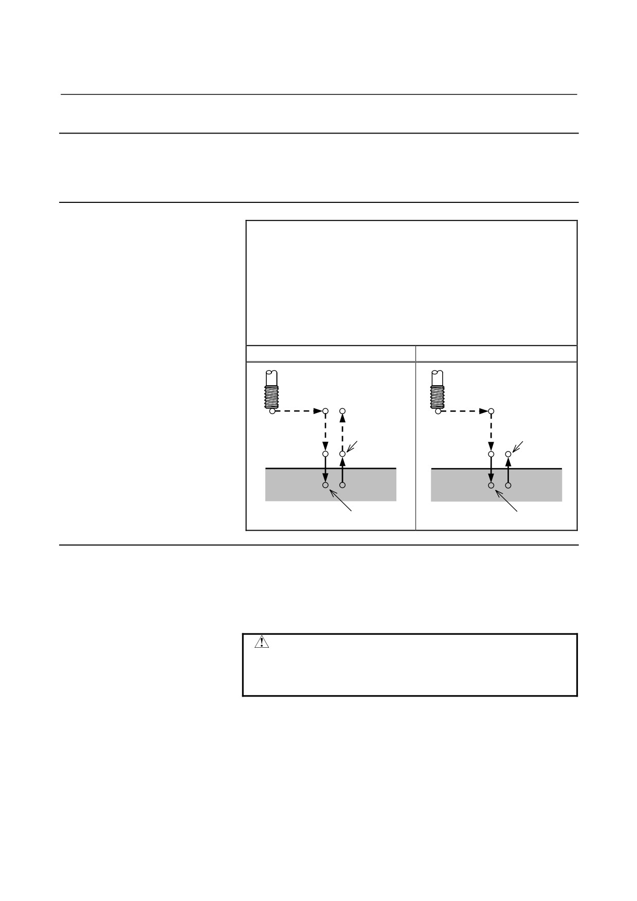
This cycle performs left-handed tapping. In the left-handed tapping
cycle, when the bottom of the hole has been reached, the spindle
rotates clockwise.
Format
G74 X_ Y_ Z_ R_ P_ Q_ F_ K_ ;
X_ Y_ : Hole position data
Z_
: The distance from point R to the bottom of the hole
R_
: The distance from the initial level to point R level
P_
: Dwell time
Q_
: Depth of cut for each cutting feed (bit 6 (PCT) of
parameter No. 5104 = "1")
F_
: Cutting feedrate
K_
: Number of repeats (if required)
G74 (G98)
G74 (G99)
Initial level
Spindle
Spindle
CCW
CCW
P
Point R
P
Point R
Point R level
Point Z
Point Z
P
P
Spindle CW
Spindle CW
Explanation
- Operations
Tapping is performed by turning the spindle counterclockwise.
When the bottom of the hole has been reached, the spindle is rotated
clockwise for retraction. This creates a reverse thread.
CAUTION
Feedrate overrides are ignored during left-handed
tapping. A feed hold does not stop the machine
until the return operation is completed.
- 36 -
5.FUNCTIONS TO SIMPLIFY
B-64304EN-2/01
PROGRAMMING
PROGRAMMING
- Spindle rotation
Before specifying G74, use an auxiliary function (M code) to rotate
the spindle counterclockwise.
If drilling is continuously performed with a small value specified for
the distance between the hole position and point R level or between
the initial level and point R level, the normal spindle speed may not be
reached at the start of hole cutting operation. In this case, insert a
dwell before each drilling operation with G04 to delay the operation,
without specifying the number of repeats for K. For some machines,
the above note may not be considered. Refer to the manual provided
by the machine tool builder.
- Q command
After setting bit 6 (PCT) of parameter No. 5104 to 1, add address Q to
the ordinary tapping cycle command format and specify the depth of
cut for each tapping.
In the peck tapping cycle, the tool is retracted to point R for each
tapping. In the high-speed peck tapping cycle, the tool is retracted
by the retraction distance specified for parameter No. 5213 in advance.
Which operation is to be performed can be selected by setting bit 5
(PCP) of parameter No. 5200.
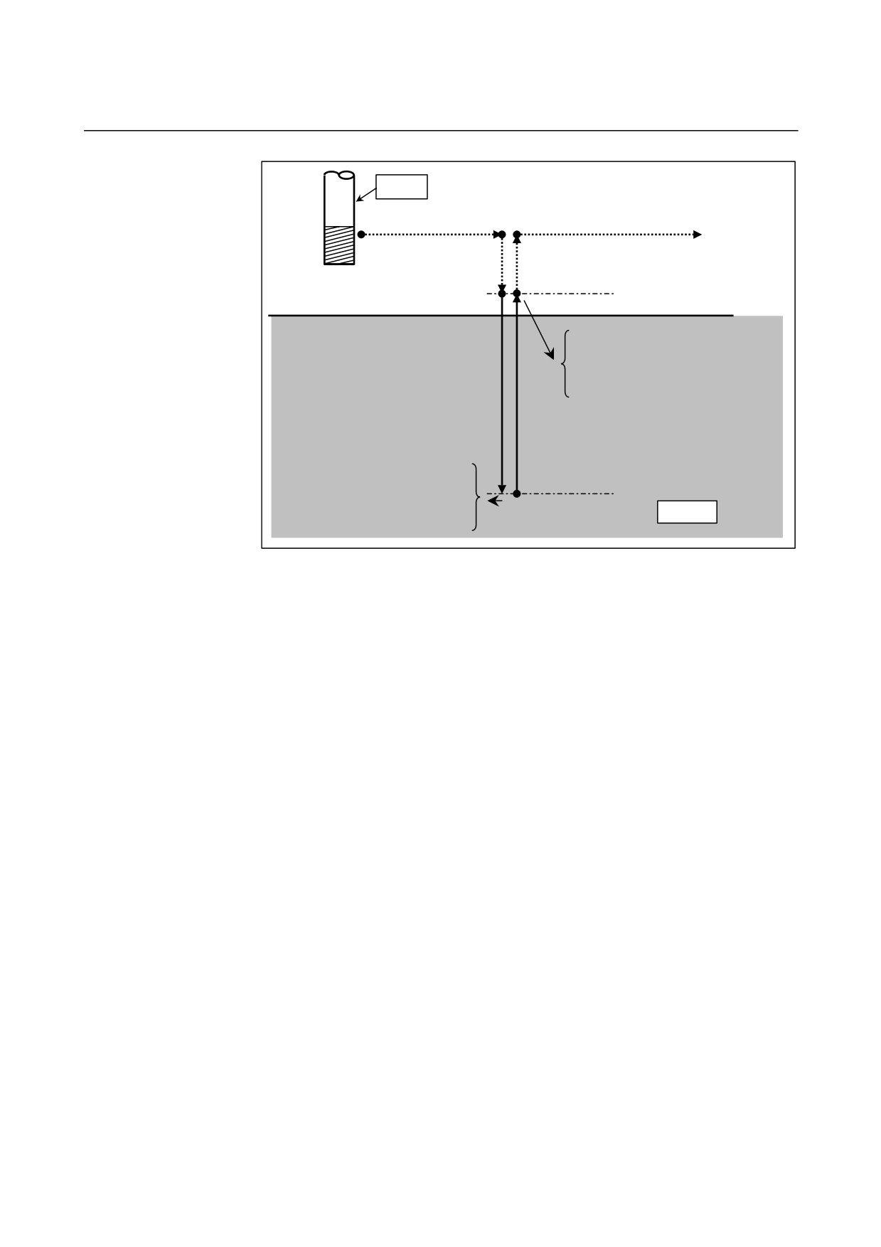
Operation
First, ordinary tapping cycle operation is explained as basic operation.
Before specifying a tapping cycle, rotate the spindle using an auxiliary
function.
1.
When a command to position the tool to a hole position,
positioning is performed.
2.
When point R is specified, positioning to point R is performed.
3.
Tapping is performed to the bottom of the hole in cutting feed.
4.
When a dwell time (P) is specified, the tool dwells.
5.
Auxiliary function M05 (spindle stop) is output and the machine
enters the FIN wait state.
6.
When FIN is returned, auxiliary function M04 (reverse spindle
rotation) is output and the machine enters the FIN wait state.
7.
When FIN is returned, the tap is removed until point R is reached
in cutting feed.
8.
When a dwell time (P) is specified, the tool dwells.
9.
Auxiliary function M05 (spindle stop) is output and the machine
enters the FIN wait state.
10. When FIN is returned, auxiliary function M03 (forward spindle
rotation) is output, and the machine enters the FIN wait state.
11. When FIN is returned, the tool returns to the initial point in rapid
traverse when return to the initial level is specified.
When the repetitive count is specified, operation is repeated from step
1.
- 37 -
5. FUNCTIONS TO SIMPLIFY
PROGRAMMING
PROGRAMMING
B-64304EN-2/01
Tapping
<1> Positioning to a hole
<1> Positioning to the next hole
<11> Positioning to the initial point
<2> Positioning to point R
Point R level
<8> Dwell
<3> Tapping to the bottom of the hole
<9> Output of auxiliary function M05
<10> Output of auxiliary function M03
<7> Return to point R
<4> Dwell
Hole bottom level
<5> Output of auxiliary function M05
Workpiece
<6> Output of auxiliary function M04
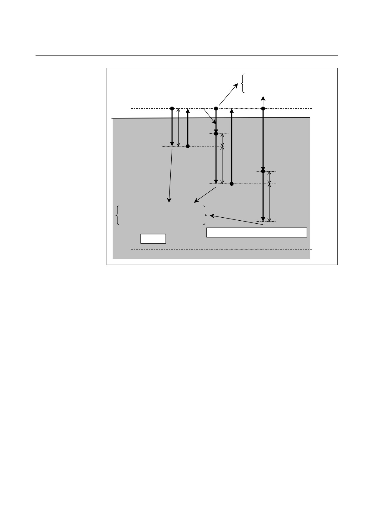
Peck tapping cycle
When bit 6 (PCT) of parameter No. 5104 is set to 1 and bit 5 (PCP) of
parameter No. 5200 is set to 1, the peck tapping cycle is used.
Step 3 of the tapping cycle operation described above changes as
follows:
3-1. The tool cuts the workpiece by the depth of cut q specified by
address Q.
3-2. Auxiliary function M05 (spindle stop) is output, and the machine
enters the FIN wait state.
3-3. When FIN is returned, auxiliary function M04 (reverse spindle
rotation) is output, and the machine enters the FIN wait state.
3-4. When FIN is returned, the tool is retracted to point R in cutting
feed.
3-5. Auxiliary function M05 (spindle stop) is output, and the machine
enters the FIN wait state.
3-6. When FIN is returned, auxiliary function M03 (forward spindle
rotation) is output, and the machine enters the FIN wait state.
3-7. When FIN is returned, the tool moves to the position the
clearance d (parameter No. 5213) apart from the previous cutting
point in cutting feed (approach).
3-1. The tool cuts the workpiece by the clearance d (parameter No.
5213) + depth of cut q (specified by address Q).
Tapping is performed to the bottom of the hole by repeating the above
steps.
When a dwell time (P) is specified, the tool dwells only when it
reaches at the bottom of the hole and reaches point R last.
- 38 -
5.FUNCTIONS TO SIMPLIFY
B-64304EN-2/01
PROGRAMMING
PROGRAMMING
q: Depth of cut
<5> Output of auxiliary function M05
d: Clearance
<6> Output of auxiliary function M03
<7> Approach
Point R level
q
<4> Retraction
<1> Tapping
d
<4> Retraction
<7> Approach
<1> Tapping
q
d
<1> Tapping
q
<2> Output of auxiliary function M05
<3> Output of auxiliary function M04
Repeated until the bottom of the hole is reached.
Workpiece
Hole bottom level
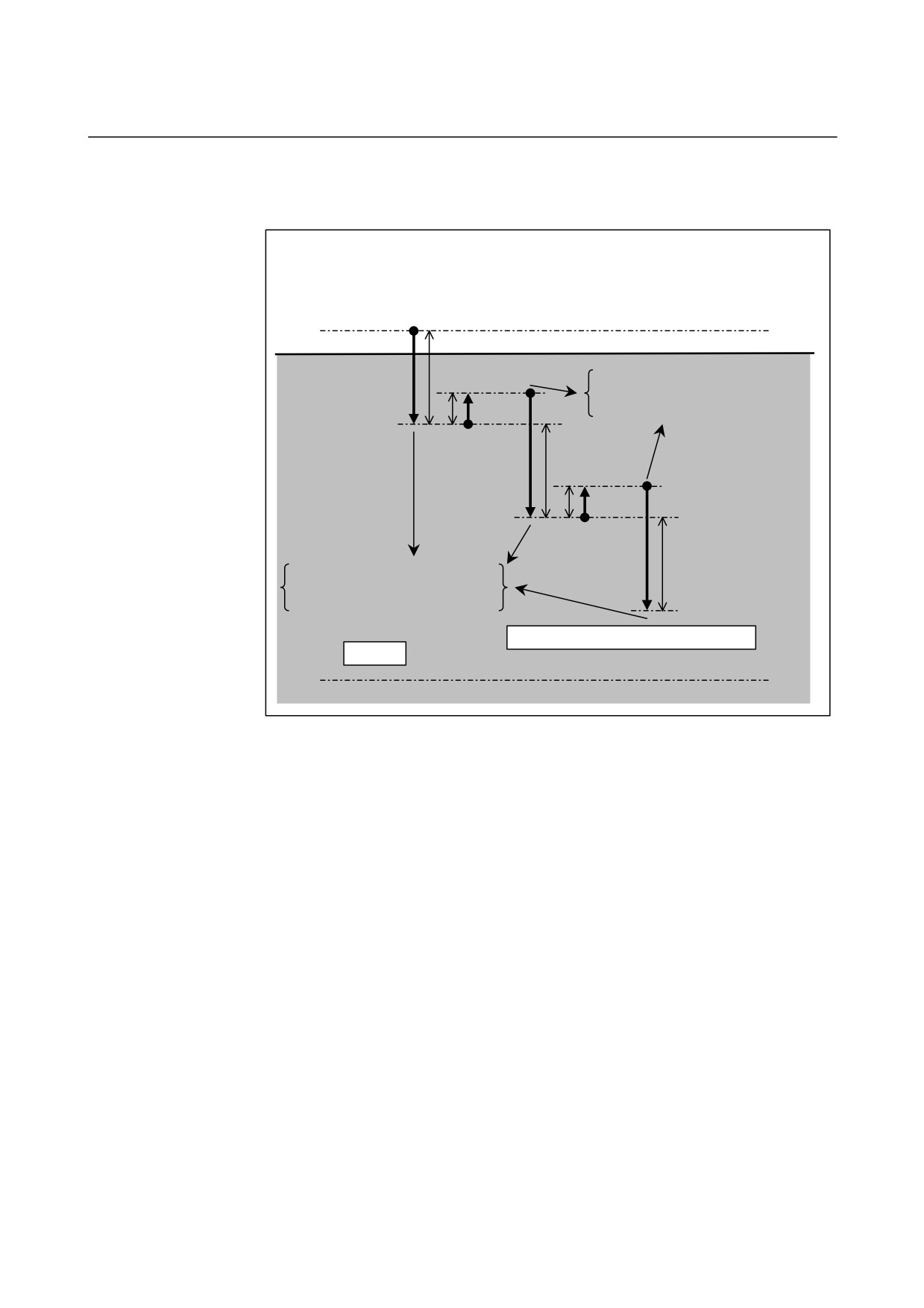
High-speed peck tapping cycle
When bit 6 (PCT) of parameter No. 5104 is set to 1 and bit 5 (PCP) of
parameter No. 5200 is set to 0, the high-speed peck tapping cycle is
used.
Step 3 of the tapping cycle operation described above changes as
follows:
3-1. The tool cuts the workpiece by the depth of cut q specified by
address Q.
3-2. Auxiliary function M05 (spindle stop) is output, and the machine
enters the FIN wait state.
3-3. When FIN is returned, auxiliary function M04 (reverse spindle
rotation) is output, and the machine enters the FIN wait state.
3-4. When FIN is returned, the tool is retracted by the retraction
distance d specified by parameter No. 5213 in cutting feed.
3-5. Auxiliary function M05 (spindle stop) is output, and the machine
enters the FIN wait state.
3-6. When FIN is returned, auxiliary function M03 (forward spindle
rotation) is output, and the machine enters the FIN wait state.
3-1. When FIN is returned, the tool cuts the workpiece by the
retraction distance d
(parameter No. 5213) + depth of cut q
(specified by address Q).
Tapping is performed to the bottom of the hole by repeating the above
steps.
- 39 -
5. FUNCTIONS TO SIMPLIFY
PROGRAMMING
PROGRAMMING
B-64304EN-2/01
When a dwell time (P) is specified, the tool dwells only
when it
reaches at the bottom of the hole and reaches point R.
q: Depth of cut
d: Retraction distance
Point R level
<1> Tapping
q
<5> Output of auxiliary function M05
<6> Output of auxiliary function M03
d
<4> Retraction
<1> Tapping
q
d
<4> Retraction
<1> Tapping
q
<2> Output of auxiliary function M05
<3> Output of auxiliary function M04
Repeated until the bottom of the hole is reached.
Workpiece
Hole bottom level
Notes
1.
The depth of cut specified by address Q is stored as a modal
value until the canned cycle mode is canceled.
In both examples 1 and 2 below, address Q is not specified in the
N20 block, but the peck tapping cycle is performed because the
value specified by address Q is valid as a modal value. If this
operation is not suitable, specify G80 to cancel the canned cycle
mode as shown in N15 in example 3 or specify Q0 in the tapping
block as shown in N20 in example 4.
Example 1
N10 G84 X100. Y150. Z-100. Q20. ;
N20 X150. Y200 ; ĸ The peck tapping cycle is also performed
in this block.
N30 G80 ;
Example 2
N10 G83 X100. Y150. Z-100. Q20. ;
N20 G84 Z-100. ; ĸ The peck tapping cycle is also performed in
this block.
N30 G80 ;
- 40 -
5.FUNCTIONS TO SIMPLIFY
B-64304EN-2/01
PROGRAMMING
PROGRAMMING
Example 3
N10 G83 X100. Y150. Z-100. Q20. ;
N15 G80 ; ĸ The canned cycle mode is canceled.
N20 G84 Z-100. ;
N30 G80 ;
Example 4
N10 G83 X100. Y150. Z-100. Q20. ;
N20 G84 Z-100. Q0 ; ĸQ0 is added.
N30 G80 ;
2.
The unit for the reference axis that is set by parameter No. 1031,
not the unit for the drilling axis is used as the unit of Q. Any
sign is ignored.
- Auxiliary function
When the G74 command and an M code are specified in the same
block, the M code is executed at the time of the first positioning
operation. When K is used to specify the number of repeats, the M
code is executed for the first hole only; for the second and subsequent
holes, the M code is not executed.
- Tool length compensation
When a tool length compensation (G43, G44, or G49) is specified in
the canned cycle for drilling, the offset is applied after the time of
positioning to point R.
Limitation
- Axis switching
Before the drilling axis can be changed, the canned cycle for drilling
must be canceled.
- Drilling
In a block that does not contain X, Y, Z, R, or any other axes, drilling
is not performed.
- P
Specify P in blocks that perform drilling. If it is specified in a block
that does not perform drilling, it cannot be stored as modal data.
- Cancel
Do not specify a G code of the 01 group (G00 to G03) and G74 in a
single block. Otherwise, G74 will be canceled.
- Tool offset
In the canned cycle mode for drilling, tool offsets are ignored.
- 41 -
5. FUNCTIONS TO SIMPLIFY
PROGRAMMING
PROGRAMMING
B-64304EN-2/01
Example
M4 S100 ;
Cause the spindle to start rotating.
G90 G99 G74 X300. Y-250. Z-150. R-120. F120. ;
Position, tapping hole 1, then return to point R.
Y-550. ;
Position, tapping hole 2, then return to point R.
Y-750. ;
Position, tapping hole 3, then return to point R.
X1000. ;
Position, tapping hole 4, then return to point R.
Y-550. ;
Position, tapping hole 5, then return to point R.
G98 Y-750. ;
Position, tapping hole 6, then return to the initial
level.
G80 G28 G91 X0 Y0 Z0
; Return to the reference position
M5 ;
Cause the spindle to stop rotating.
- 42 -
5.FUNCTIONS TO SIMPLIFY
B-64304EN-2/01
PROGRAMMING
PROGRAMMING
5.1.3
Fine Boring Cycle (G76)
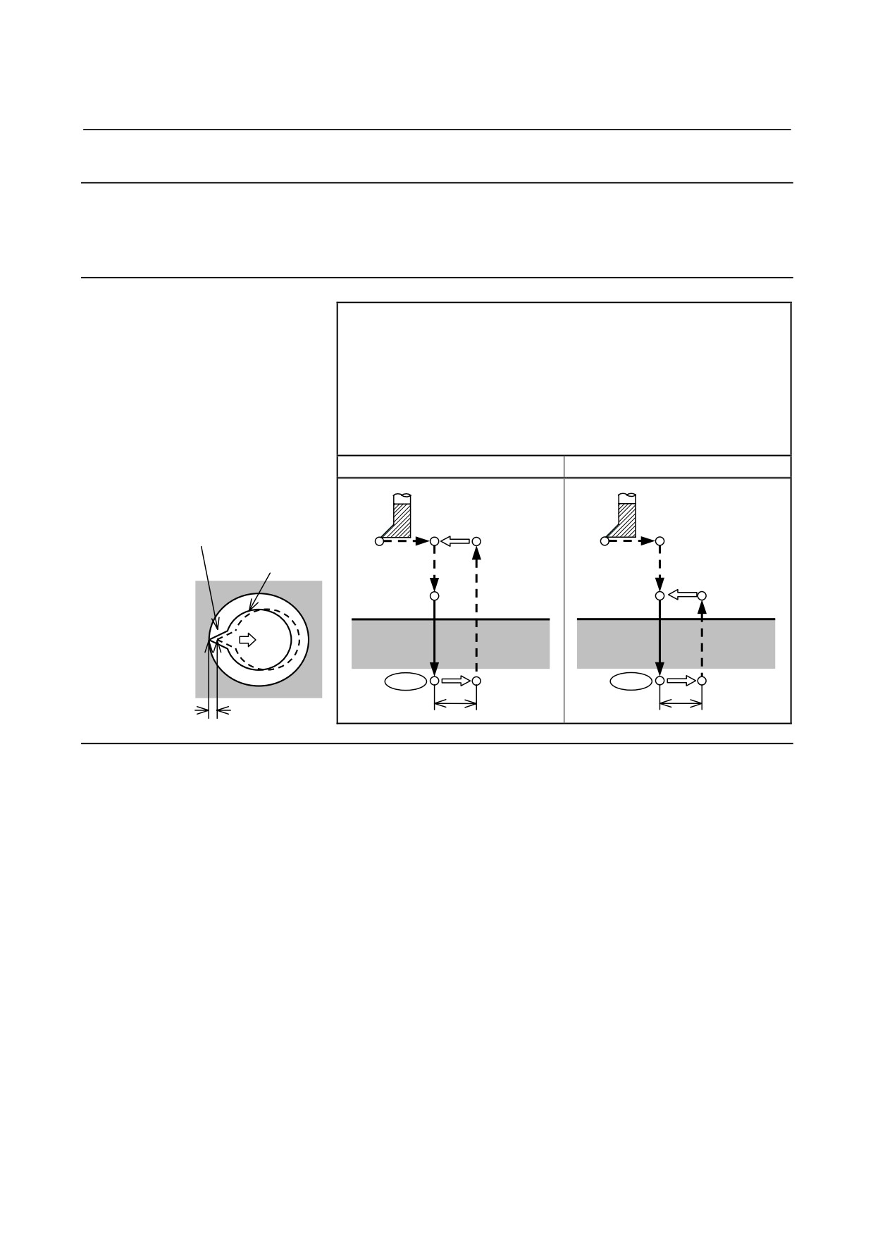
The fine boring cycle bores a hole precisely. When the bottom of the
hole has been reached, the spindle stops, and the tool is moved away
from the machined surface of the workpiece and retracted.
Format
G76 X_ Y_ Z_ R_ Q_ P_ F_ K_ ;
X_ Y_ : Hole position data
Z_
: The distance from point R to the bottom of the hole
R_
: The distance from the initial level to point R level
Q_
: Shift amount at the bottom of a hole
P_
: Dwell time at the bottom of a hole
F_
: Cutting feedrate
K_
: Number of repeats (if required)
G76 (G98)
G76 (G99)
Spindle CW
Spindle orientation
Initial level
Tool
Spindle CW
Point R level
Point R
Point R
P
P
OSS
OSS
Point Z
Point Z
q
q
Shift amount q
Explanation
- Operations
When the bottom of the hole has been reached, the spindle is stopped
at the fixed rotation position, and the tool is moved in the direction
opposite to the tool nose and retracted. This ensures that the
machined surface is not damaged and enables precise and efficient
boring to be performed.
- Spindle rotation
Before specifying G76, use a Auxiliary function (M code) to rotate the
spindle.
- Auxiliary function
When the G76 command and an M code are specified in the same
block, the M code is executed at the time of the first positioning
operation. When K is used to specify the number of repeats, the M
code is executed for the first hole only; for the second and subsequent
holes, the M code is not executed.
- 43 -
5. FUNCTIONS TO SIMPLIFY
PROGRAMMING
PROGRAMMING
B-64304EN-2/01
- Tool length compensation
When a tool length compensation (G43, G44, or G49) is specified in
the canned cycle for drilling, the offset is applied after the time of
positioning to point R.
Limitation
- Axis switching
Before the drilling axis can be changed, the canned cycle for drilling
must be canceled.
- Drilling
In a block that does not contain X, Y, Z, R, or any additional axes,
drilling is not performed.
- P/Q
Be sure to specify a positive value in Q. If Q is specified with a
negative value, the sign is ignored. Set the direction of shift in the
parameter (No.5148).
Specify P and Q in a block that performs drilling. If they are
specified in a block that does not perform drilling, they are not stored
as modal data.
CAUTION
Q (shift at the bottom of a hole) is a modal value
retained within canned cycles for drilling. It must
be specified carefully because it is also used as the
depth of cut for G73 and G83.
- Cancel
Do not specify a G code of the 01 group (G00 to G03) and G76 in a
single block. Otherwise, G76 will be canceled.
- Tool offset
In the canned cycle mode for drilling, tool offsets are ignored.
Example
M3 S500 ;
Cause the spindle to start rotating.
G90 G99 G76 X300. Y-250.
Position, bore hole 1, then return to point R.
Z-150. R-120. Q5.
Orient at the bottom of the hole, then shift by 5
mm.
P1000 F120. ;
Stop at the bottom of the hole for 1 s.
Y-550. ;
Position, drill hole 2, then return to point R.
Y-750. ;
Position, drill hole 3, then return to point R.
X1000. ;
Position, drill hole 4, then return to point R.
Y-550. ;
Position, drill hole 5, then return to point R.
G98 Y-750. ;
Position, drill hole 6, then return to the initial level.
G80 G28 G91 X0 Y0 Z0 ;
Return to the reference position
M5 ;
Cause the spindle to stop rotating.
- 44 -
5.FUNCTIONS TO SIMPLIFY
B-64304EN-2/01
PROGRAMMING
PROGRAMMING
5.1.4
Drilling Cycle, Spot Drilling (G81)
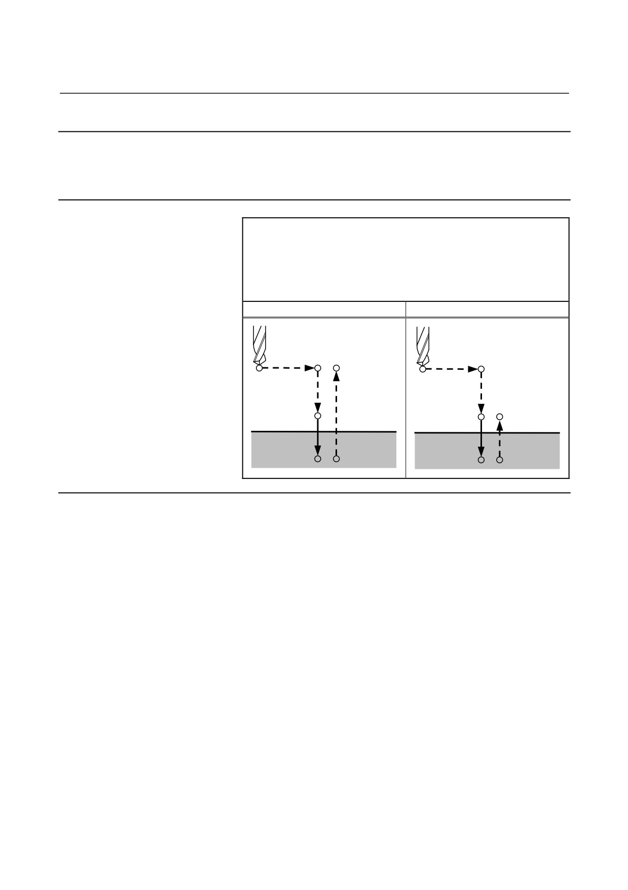
This cycle is used for normal drilling. Cutting feed is performed to
the bottom of the hole. The tool is then retracted from the bottom of
the hole in rapid traverse.
Format
G81 X_ Y_ Z_ R_ F_ K_ ;
X_ Y_ : Hole position data
Z_
: The distance from point R to the bottom of the hole
R_
: The distance from the initial level to point R level
F_
: Cutting feedrate
K_
: Number of repeats (if required)
G81 (G98)
G81 (G99)
Initial level
Point R
Point R
Point R level
Point Z
Point Z
Explanation
- Operations
After positioning along the X- and Y-axes, rapid traverse is performed
to point R.
Drilling is performed from point R to point Z.
The tool is then retracted in rapid traverse.
- Spindle rotation
Before specifying G81, use an auxiliary function (M code) to rotate
the spindle.
- Auxiliary function
When the G81 command and an M code are specified in the same
block, the M code is executed at the time of the first positioning
operation. When K is used to specify the number of repeats, the M
code is performed for the first hole only; for the second and
subsequent holes, the M code is not executed.
- Tool length compensation
When a tool length compensation (G43, G44, or G49) is specified in
the canned cycle for drilling, the offset is applied after the time of
positioning to point R.
- 45 -