FANUC Series 0i-MODEL C, Series 0i Mate-MODEL C. PARAMETER MANUAL (B-64120EN/01) - page 14
4.DESCRIPTION OF PARAMETERS
B-64120EN/01
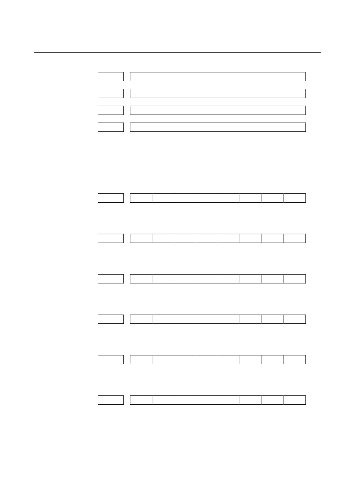
12857
Number of a signal selected as an operation history signal (17)
12858
Number of a signal selected as an operation history signal (18)
12859
Number of a signal selected as an operation history signal (19)
12860
Number of a signal selected as an operation history signal (20)
[Data type]
Word
[Valid data range]
0 to 511
Set the number of a signal of which operation history is to be recorded
for operation history channel (01) to (20) with a value between 0 and
511.
#7
#6
#5
#4
#3
#2
#1
#0
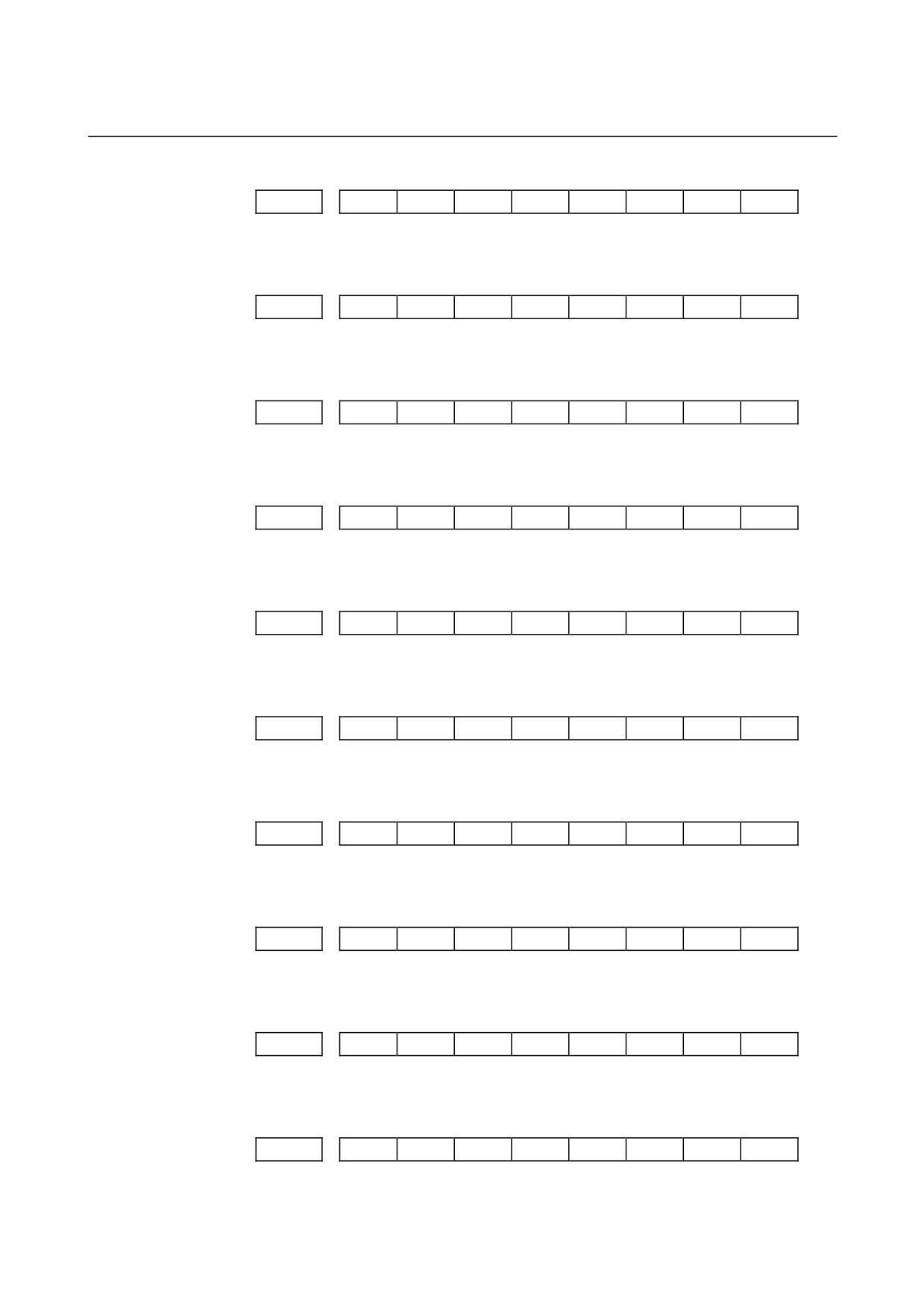
12881
RB7
RB6
RB5
RB4
RB3
RB2
RB1
RB0
History record bit settings for an operation history signal (01)
#7
#6
#5
#4
#3
#2
#1
#0
12882
RB7
RB6
RB5
RB4
RB3
RB2
RB1
RB0
History record bit settings for an operation history signal (02)
#7
#6
#5
#4
#3
#2
#1
#0
12883
RB7
RB6
RB5
RB4
RB3
RB2
RB1
RB0
History record bit settings for an operation history signal (03)
#7
#6
#5
#4
#3
#2
#1
#0
12884
RB7
RB6
RB5
RB4
RB3
RB2
RB1
RB0
History record bit settings for an operation history signal (04)
#7
#6
#5
#4
#3
#2
#1
#0
12885
RB7
RB6
RB5
RB4
RB3
RB2
RB1
RB0
History record bit settings for an operation history signal (05)
#7
#6
#5
#4
#3
#2
#1
#0
12886
RB7
RB6
RB5
RB4
RB3
RB2
RB1
RB0
History record bit settings for an operation history signal (06)
- 382 -
B-64120EN/01
4.DESCRIPTION OF PARAMETERS
#7
#6
#5
#4
#3
#2
#1
#0
12887
RB7
RB6
RB5
RB4
RB3
RB2
RB1
RB0
History record bit settings for an operation history signal (07)
#7
#6
#5
#4
#3
#2
#1
#0
12888
RB7
RB6
RB5
RB4
RB3
RB2
RB1
RB0
History record bit settings for an operation history signal (08)
#7
#6
#5
#4
#3
#2
#1
#0
12889
RB7
RB6
RB5
RB4
RB3
RB2
RB1
RB0
History record bit settings for an operation history signal (09)
#7
#6
#5
#4
#3
#2
#1
#0
12890
RB7
RB6
RB5
RB4
RB3
RB2
RB1
RB0
History record bit settings for an operation history signal (10)
#7
#6
#5
#4
#3
#2
#1
#0
12891
RB7
RB6
RB5
RB4
RB3
RB2
RB1
RB0
History record bit settings for an operation history signal (11)
#7
#6
#5
#4
#3
#2
#1
#0
12892
RB7
RB6
RB5
RB4
RB3
RB2
RB1
RB0
History record bit settings for an operation history signal (12)
#7
#6
#5
#4
#3
#2
#1
#0
12893
RB7
RB6
RB5
RB4
RB3
RB2
RB1
RB0
History record bit settings for an operation history signal (13)
#7
#6
#5
#4
#3
#2
#1
#0
12894
RB7
RB6
RB5
RB4
RB3
RB2
RB1
RB0
History record bit settings for an operation history signal (14)
#7
#6
#5
#4
#3
#2
#1
#0
12895
RB7
RB6
RB5
RB4
RB3
RB2
RB1
RB0
History record bit settings for an operation history signal (15)
#7
#6
#5
#4
#3
#2
#1
#0
12896
RB7
RB6
RB5
RB4
RB3
RB2
RB1
RB0
History record bit settings for an operation history signal (16)
- 383 -

4.DESCRIPTION OF PARAMETERS
B-64120EN/01
#7
#6
#5
#4
#3
#2
#1
#0
12897
RB7
RB6
RB5
RB4
RB3
RB2
RB1
RB0
History record bit settings for an operation history signal (17)
#7
#6
#5
#4
#3
#2
#1
#0
12898
RB7
RB6
RB5
RB4
RB3
RB2
RB1
RB0
History record bit settings for an operation history signal (18)
#7
#6
#5
#4
#3
#2
#1
#0
12899
RB7
RB6
RB5
RB4
RB3
RB2
RB1
RB0
History record bit settings for an operation history signal (19)
#7
#6
#5
#4
#3
#2
#1
#0
12900
RB7
RB6
RB5
RB4
RB3
RB2
RB1
RB0
History record bit settings for an operation history signal (20)
[Data type] Bit
RB7 to RB0 In the signals set for channels (01) to (20) (parameter Nos. 12801 to
12860), of which operation history is to be recorded, the history of
each bit is:
0 : Not recorded. (The history of this bit is not recorded.)
1 : Recorded. (The history of this bit is recorded.)
- 384 -
B-64120EN/01
4.DESCRIPTION OF PARAMETERS
4.57
PARAMETERS OF DISPLAY AND EDIT (2/2)
#7
#6
#5
#4
#3
#2
#1
#0
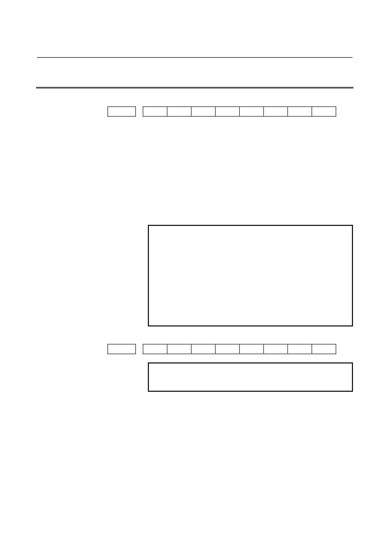
13101
ODC
NDC
[Data type]
Bit
NDC
The color scheme (color palette value) of VGA-compatible screens on
a color LCD is:
0 : Not changed.
1 : Changed to FANUC standard colors 1 (new FANUC standard
colors).
ODC
The color scheme (color palette value) of VGA-compatible screens on
a color LCD is:
0 : Not changed.
1 : Changed to FANUC standard colors 2 (old FANUC standard
colors).
NOTE
1 After bit 6 (NDC) of parameter No. 13101 is set to
1, turning the power off then back on resets the bit
to 0 automatically.
2 After bit 7 (ODC) of parameter No. 13101 is set to
1, turning the power off then back on resets the bit
to 0 automatically.
3 If the standard color data parameters of color
scheme 1 (parameter Nos. 6561 to 6595) are all
set to 0, the color scheme settings can be changed
by setting parameter NDC or ODC to 1.
#7
#6
#5
#4
#3
#2
#1
#0
13110
JPN
NOTE
When this parameter is set, the power must be
turned off before operation is continued.
[Data type]
Bit
JPN
As the display language used for failure diagnosis and machine alarm
diagnosis:
0 : English has precedence.
For machine alarm diagnosis, the GUIE_USR.MEM file has
precedence.
1 : Japanese has precedence.
For machine alarm diagnosis, the GUIJ_USR.MEM file has
precedence.
- 385 -

4.DESCRIPTION OF PARAMETERS
B-64120EN/01
#7
#6
#5
#4
#3
#2
#1
#0
13112
SPI
SVI
IDW
[Data type]
Bit
IDW
Editing on the servo information screen or spindle information screen
is
0 : Prohibited.
1 : Not prohibited.
SVI
Servo information screen is
0 : Displayed.
1 : Not displayed.
SPI
Spindle information screen is
0 : Displayed.
1 : Not displayed.
13150
Number of sets of offset data displayed on the offset screen
[Data type]
Word
[Valid data range]
0, 1 to the maximum sets of tool offset data
This parameter sets the number of sets of offset data to be displayed
on the offset screen.
NOTE
1 When this parameter is set, the power must be
turned off before operation is continued.
2 If 0 or a value beyond the data range is set in this
parameter, the setting of this parameter becomes
invalid, and all offset data is displayed.
- 386 -
B-64120EN/01
4.DESCRIPTION OF PARAMETERS
4.58
PARAMETERS OF MACHINING CONDITION SELECTION
#7
#6
#5
#4
#3
#2
#1
#0
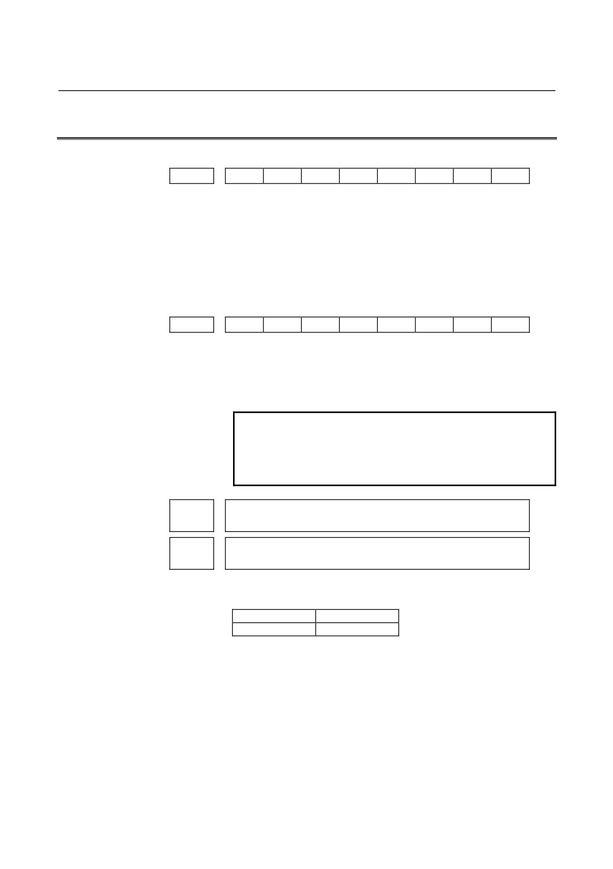
13600
MCR
[Data type]
Bit
MCR
When the permissible acceleration is adjusted with the machining
condition selection function (machining parameter adjustment screen
or precision level selection screen), parameter Nos. No.1730 and 1731,
which are related to feedrate clamping by arc radius, are:
0 : Changed.
1 : Not changed.
#7
#6
#5
#4
#3
#2
#1
#0
13601
MPR
[Data type]
Bit
MPR
The machining parameter adjustment screen is:
0 : Displayed.
1 : Not displayed.
NOTE
1 When this parameter has been set, the power must
be turned off before operation is continued.
2 Even when this parameter is set to 1, the precision
level selection screen is displayed.
Acceleration rate of acceleration/deceleration before interpolation when
13610
advanced preview control, AI advanced preview control, or AI contour
control is used (precision level 1)
Acceleration rate of acceleration/deceleration before interpolation when
advanced preview control, AI advanced preview control, or AI contour
13611
control is used (precision level 10)
[Data type]
2-word
[Unit of data]
%
Increment system
Unit
Millimeter machine
0.001mm/sec2
[Valid data range]
50000 to 99999999
These parameters set the acceleration rate of acceleration/deceleration
before interpolation in advanced preview control, AI advanced
preview control, or AI contour control. Two levels including precision
level
1, which places emphasis on speed, and precision level 10,
which places emphasis on precision, can be set.
- 387 -
4.DESCRIPTION OF PARAMETERS
B-64120EN/01
13612
Acceleration change time when AI contour control is used (bell-shaped)
(precision level 1)
13613
Acceleration change time when AI contour control is used (bell-shaped)
(precision level 10)
[Data type]
Byte
[Unit of data]
msec
[Valid data range]
1 to 100
These parameters set an acceleration change time (bell-shaped) with
emphasis placed on speed (precision level 1) and an acceleration
change time
(bell-shaped) with emphasis placed on precision
(precision level 10) in AI contour control.
Permissible acceleration when advanced preview control, AI advanced
13620
preview control, or AI contour control is used (precision level 1)
Permissible acceleration when advanced preview control, AI advanced
13621
preview control, or AI contour control is used (precision level 10)
[Data type]
2-word axis
[Unit of data]
Increment system
Unit
Millimeter machine
0.001mm/sec2
[Valid data range]
0 to 99999999
These parameters set a permissible acceleration with emphasis placed
on speed (precision level
1) and a permissible acceleration with
emphasis placed on precision (precision level 10) in advanced preview
control, AI advanced preview control, or AI contour control.
Time constant of acceleration/deceleration after interpolation
13622
(precision level 1)
Time constant of acceleration/deceleration after interpolation
13623
(precision level 10)
[Data type]
Word axis
[Unit of data]
msec
[Valid data range]
See the description of parameter No. 1768.
These
parameters
set
a
time
constant
of
linear
acceleration/deceleration after interpolation with emphasis placed on
speed
(precision level
1) and a time constant of linear
acceleration/deceleration after interpolation with emphasis placed on
precision (precision level 10).
The linear or bell-shaped type is selected by bit 3 (BS2) and bit 6
(LS2) of parameter No. 1602.
Parameter No.1602
Acceleration/deceleration
LS2(#6)
BS2(#3)
1
0
Selects linear acceleration/deceleration after cutting
feed interpolation.
0
1
Selects bell-shaped acceleration/deceleration after
cutting feed interpolation.
- 388 -
B-64120EN/01
4.DESCRIPTION OF PARAMETERS
NOTE
1 For bell-shaped acceleration/deceleration, the
function for bell-shaped acceleration/deceleration
after cutting feed interpolation is required.
2 The same parameters are used in advanced
preview control, AI advanced preview control, and
AI contour control.
Difference in corner speed when advanced preview control, AI advanced
13624
preview control, or AI contour control is used (precision level 1)
Difference in corner speed when advanced preview control, AI advanced
13625
preview control, or AI contour control is used (precision level 10)
[Data type]
Word axis
[Unit of data, valid data range]
Valid data range
Increment system
Units of data
IS-B
IS-C
Millimeter machine
1 mm/min
6 to 15000
6 to 12000
Rotation axis
1 deg/min
6 to 15000
6 to 12000
These parameters set a permissible speed difference with emphasis
placed on speed (precision level 1) and a permissible speed difference
with emphasis placed on precision (precision level 10) when the speed
is determined by a corner speed difference in advanced preview
control, AI advanced preview control, or AI contour control.
13626
Maximum machining speed (precision level 1)
13627
Maximum machining speed (precision level 10)
[Data type]
2-word axis
[Unit of data, valid data range]
Valid data range
Increment system
Units of data
IS-B
IS-C
Millimeter machine
1 mm/min
6 to 24000
6 to 100000
Rotation axis
1 deg/min
6 to 24000
6 to 100000
These parameters set the maximum machining speed for each axis.
- 389 -
4.DESCRIPTION OF PARAMETERS
B-64120EN/01
Parameter number for arbitrary item 1 when advanced preview control, AI
13628
advanced preview control, or AI contour control is used
Parameter number for arbitrary item 2 when advanced preview control, AI
13629
advanced preview control, or AI contour control is used
[Data type]
Word
[Valid data range]
1 to 65535
These parameters specify parameter numbers corresponding to
arbitrary items 1 and 2.
NOTE
1 You cannot specify the numbers of the following
parameters:
- Bit parameters
- Spindle parameters (Nos. 4000 to 4799)
- Parameters requiring power disconnection (P/S
0 alarm is issued for these parameters.)
- Nonexistent parameters
2 When such a parameter is set, the power must be
turned off before operation is continued.
Value of the parameter corresponding to arbitrary item 1 with emphasis
13630
placed on speed (precision level 1) when advanced preview control, AI
advanced preview control, or AI contour control is used
Value of the parameter corresponding to arbitrary item 2 with emphasis
placed on speed (precision level 1) when advanced preview control, AI
13631
advanced preview control, or AI contour control is used
Value of the parameter corresponding to arbitrary item 1 with emphasis
13632
placed on speed (precision level 10) when advanced preview control, AI
advanced preview control, or AI contour control is used
Value of the parameter corresponding to arbitrary item 2 with emphasis
13633
placed on speed (precision level 10) when advanced preview control, AI
advanced preview control, or AI contour control is used
[Data type]
2-word axis
[Unit of data]
Depending on the type of the parameter for an item
[Valid data range]
Depending on the type of the parameter for an item
Precision level currently selected when advanced preview control, AI
13634
advanced preview control, or AI contour control is used
[Data type]
Byte
[Valid data range]
1 to 10
The currently selected level is set.
- 390 -

B-64120EN/01
4.DESCRIPTION OF PARAMETERS
4.59
PARAMETERS OF SERVO (2)
Maximum permissible movement amount at FL feedrate when the reference
14010
position is established with an encoder with the absolute address zero point
(detection circuit C)
[Data type]
2-word axis
[Unit of data]
Detection unit
[Valid data range]
0 to 99999999
This parameter sets the amount of a movement made at the FL
feedrate when the reference position is established with an encoder
with the absolute address zero point (linear scale or rotary encoder)
(detection circuit C). If the reference position is not established even
when a movement is made by the amount set in this parameter or more,
P/S alarm
5326 (Scale with the zero point: Failure in reference
position establishment) is issued. When this parameter is set to 0, the
maximum permissible movement amount at the FL feedrate at the
time of reference position establishment becomes invalid.
NOTE
1 When the reference position is established under
simplified synchronization control of the M series, if
this parameter is set for one of the master and
slave axes, the setting automatically applies also to
the other axis.
2 In angular axis control, the setting of this parameter
is invalid for a Cartesian axis with which angular
axis reference position is being established.
- 391 -

B-64120EN/01
APPENDIX
A.CHARACTER CODE LIST
A
CHARACTER CODE LIST
Character
Code
Comment
Character
Code
Comment
A
065
6
054
B
066
7
055
C
067
8
056
D
068
9
057
E
069
032
Space
F
070
!
033
Exclamation mark
G
071
”
034
Quotation marks
H
072
#
035
Sharp
I
073
$
036
Dollar mark
J
074
%
037
Percent
K
075
&
038
Ampersand
L
076
’
039
Apostrophe
M
077
(
040
Left parenthesis
N
078
)
041
Right parenthesis
O
079
042
Asterisk
P
080
+
043
Positive sign
Q
081
,
044
Comma
R
082
-
045
Negative sign
S
083
046
Period
T
084
/
047
Slash
U
085
:
058
Colon
V
086
;
059
Semicolon
W
087
<
060
Left angle bracket
X
088
=
061
Equal sign
Y
089
>
062
Right angle bracket
Z
090
?
063
Question mark
0
048
@
064
Commercial at mark
1
049
[
091
Left square bracket
2
050
094
3
051
¥
092
Yen mark
4
052
]
093
Right square bracket
5
053
_
095
Underline
- 395 -